1
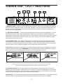
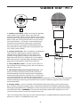
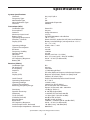
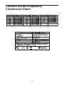
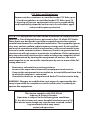
Copyright 2009, Samson Technologies Corp.
Printed, January 2009 v1
Samson Technologies Corp.
45 Gilpin Avenue
Hauppauge, New York 11788-8816
Phone: 1-800-3-SAMSON (1-800-372-6766)
Fax: 631-784-2201
www.samsontech.com
Table of Contents
Introduction / System Features . . . . . . . . . . . . . . . . . . . . . . . . . 1
System Features . . . . . . . . . . . . . . . . . . . . . . . . . . . . . . . . . . . 2
Guided Tour - CR277 Front Panel . . . . . . . . . . . . . . . . . . . . . . . . 3
Guided Tour - CR277 Rear Panel . . . . . . . . . . . . . . . . . . . . . . . . . 4
Guided Tour - HT7 . . . . . . . . . . . . . . . . . . . . . . . . . . . . . . . . . . 5
Setting Up and Using the Concert Series System . . . . . . . . . . . . 6-8
Specifications . . . . . . . . . . . . . . . . . . . . . . . . . . . . . . . . . . . . 9
Concert Series Frequency Conversion Chart . . . . . . . . . . . . . . . . 10
Introduction / System Features
Congratulations on purchasing the Samson CR277 Dual Microphone Wireless System!
The CR277 system is the perfect solution for any application requiring two, high
quality, wireless microphones in a compact package. The system features the CR277
dual channel, diversity receiver including dual antennas, vivid RF meters and Peak
indicators for each channel, plus individual and mixed balanced outputs jacks. Also
included are two HT7 handheld microphone transmitters fitted with the Samson Q7
dynamic microphone element. The Q7 produces a robust and articulate sound thanks
to its extended frequency response and its cardioid pick-up pattern greatly reduces
the chance of feedback. With the CR277 system, you’ll have great sound quality
with clear reception and the ability to walk freely around your venue. For live sound,
karaoke, school, conferences, and Houses of Worship the CR277 is an ideal solution for
dual channel wireless microphones providing outstanding performance and reliably.
Although this product is designed for easy operation, we suggest you first take some
time to go through these pages so you can fully understand how we’ve implemented a
number of unique features. Your wireless system consists of three components— two
microphone transmitters and a dual channel receiver, which must be tuned to the
same channels (that is, the same radio frequency) in order to operate correctly.
The Samson Concert Series system you have purchased operates in the HDTV free UHF
frequency range and contains a CR277 dual channel receiver and two of our HT7 handheld microphone transmitters with the Samson Q7 dynamic capsule.
In this manual, you’ll find a detailed description of the features of the Concert
Series Wireless system, as well as a guided tour through all components, step-bystep instructions for setting up your system, wiring diagrams and tables, and full
specifications. If your Concert Series system was purchased in the United States, you’ll
also find a warranty card enclosed—don’t forget to fill it out and mail it! This will
enable you to receive online technical support and will allow us to send you updated
information about this and other Samson products in the future. Also, be sure to
check out our website (www.samsontech.com) for complete information about our full
product line.
SPECIAL NOTE for U.S. purchasers: Should your Concert Series Wireless system ever
require servicing, a Return Authorization number (RA) is necessary. Without this
number, the unit will not be accepted. If your Concert SeriesWireless system was
purchased in the United States, please call Samson at 1-800-372-6766 for a Return
Authorization number prior to shipping your unit. If possible, return the unit in its
original carton and packing materials. If your Concert Series Wireless system was
purchased outside of the U. S., contact your local distributor for servicing information.
* Your receiver and transmitter have been factory preset to utilize the same channel.
A listing of the six available channels and their corresponding UHF frequencies can be
found on page 10 of this manual.
System Features
Designed for use in both live sound and sound contracting applications, the Samson
Concert Series Wireless System provides a high performance, cost effective solution,
utilizing state-of-the-art technology in wireless communications. Main features
include:
•Six different available channels in three pairs, all operating in the less crowded
UHF bandwidth, and all designed for simultaneous use. This means that you can
use multiple Concert Series systems (each tuned to different channels) in the same
location without interference.
•Technological breakthrough usage of Dielectric filters for extremely precise and
stable tuning.
•Diversity technology maximizes active range (up to 300 feet) and reduces potential
interference problems.
•The CR277 receiver is a half-rack unit that can be used freestanding or can be
mounted in any standard 19" rack,* making it easy to integrate into any traveling or
fixed installation audio system. It includes a pair of tuned antennas and provides
both balanced and unbalanced outputs, and continuously adjustable Volume and
Squelch controls, as well as an audio peak LED, a six-segment Audio level meter and a
six-segment RF level meter.
•Built-in companding noise reduction in all components for crystal-clear sound with
minimized background noise and hiss.
•Transmitters provide “popless” muting (which turns off the audio signal while leaving
the carrier signal on) and use standard 9-volt batteries, with battery life of more than
12 hours. The Concert transmitters also provide a convenient Battery Strength LED
meter, allowing you to monitor the remaining power in the installed battery.
•The HT7 hand-held microphone transmitter is fitted with the Samson Q7 Neodymium
dynamic microphone capsule.
•All components have rugged construction that ensures reliable operation in even the
most demanding performance environments.
* Using an optional Samson RK55 rack adapter kit
Guided Tour - CR277 Front Panel
1: Antennas (Channels A and B) - The antenna mountings allow full rotation for optimum
placement. In normal operation, both Antenna A (the antenna on the left) and Antenna
B (the antenna on the right) should be placed in a vertical position. Both antennas can be
folded inward for convenience when transporting the CR277. See the “Setting Up and Using
the Concert Series System” section on page 6 in this manual for information about antenna
installation and positioning.
2: RF (Radio Frequency) Level meter - This “ladder” display (similar to the VU bar meter used
on audio devices) indicates the strength of the incoming radio signal. When the “100%” segment
is lit, the incoming RF signal is fully modulated and at optimum strength. When only the second
most left-most “10%” segment is lit, the incoming signal is at just 10% of optimum strength. If no
segments are lit, little or no signal is being received. See the “Setting Up and Using the Concert
Series System” section on page 6 in this manual for more information.
3: Volume (Channel B) / Power switch - Use this to turn the CR277 power on and off. When
the receiver is on, the Power LED is lit. The control knob sets the level of the audio signal being
output through the Channel B output jack on the rear panel (see #2 on page 4 in this manual).
Reference level is obtained when the knob is turned fully clockwise (to its “10” setting).
4: Audio PEAK LED - When the LED is lit, the signal is overloading and the HT7's input Level
adjustment must be attenuated. See the “Setting Up and the Concert Series System” section on
page 6 in this manual for more information.
5: Power LED - When the receiver is on, the red Power LED will illuminate.
6: Volume control (Channel A) - This knob sets the level of the audio signal being output
through the Channel A output jack on the rear panel (see #6 on page 4 in this manual).
Reference level is obtained when the knob is turned fully clockwise (to its “10” setting).
Guided Tour - CR277 Rear Panel
1
2
4
3
5
6
CR277
1: MIX OUT switch - Sets the OUTPUT B balanced output to send either the combined signal for
Channel A and B when the switch is in the "ON" position, or to just Channel B when in the "OFF"
position. See the “Setting Up and Using the Concert Series System” section on page 6 in this
manual for more information.
2: OUTPUT B / MIX OUT - Use this electronically balanced low impedance (600 Ohm) 1/4-inch
TRS (Tip Ring Sleeve) jack when connecting the CR277 to your mixer or amplifier equipment.
Depending on the position of the MIX OUT (#1) switch, the jack will carry the signal from receiver
Channel B, or with the MIX OUTPUT switch set to "ON", the jack will carry the combined signal
from receiver Channel A and B.
3: Squelch B control - This control determines the maximum range of the CR277 Channel B
receiver before audio signal dropout. Although it can be adjusted using the supplied plastic
screwdriver, it should normally be left at its factory setting. See the “Setting Up and Using the
Concert Series System” section on page 6 in this manual for more information.
4: DC input - Connect the supplied 15 volt 350 mA power adapter here, using the strain relief as
shown in the illustration below. WARNING: Do not substitute any other kind of power adapter;
doing so can cause severe damage to the CR277 and will void your warranty.
-
Using the strain relief: Gather up a loop of wire and pass it through the strain relief,
then pass the adapter plug through the loop in order to create a knot.
5: Squelch A control - This control determines the maximum range of the CR277 Channel A
before audio signal dropout. Although it can be adjusted using the supplied plastic screwdriver,
it should normally be left at its factory setting. See the “Setting Up and Using the Concert Series
System” section on page 6 in this manual for more information.
6: OUTPUT A - Use this electronically balanced low impedance (600 Ohm) 1/4-inch TRS (Tip Ring
Sleeve) jack when connecting the CR277 Channel A receiver to your mixer or amplifier.
Guided Tour - HT7
1: Audio on-off switch - When set to the “on” position,
audio signal is transmitted. When set to the “off”
position, the audio signal is muted. Because the carrier
signal remains during muting, no “pop” or “thud” will be
heard. Note that turning this off does not turn off the
transmitter power—it is simply a way to temporarily
mute the transmission of audio signal. If you don’t
plan on using the transmitter for extended periods,
turn off the transmitter power by using the power ONOFF switch (see #3 below).
2: Battery level meter - This set of three multicolored
LEDs indicates relative battery power, indicating
whether the installed battery is at low (red), mid
(yellow) or high (green) strength. One of these will
light whenever the HT7 is powered on (see #3 below).
When the red “low” indicator lights, RF performance is
degraded and the battery needs to be replaced.
3: Power ON-OFF switch* - Use this to turn the HT7
on or off (to conserve battery power, be sure to leave it
off when not in use).
4: Microphone Input Level control (trim-pot) - This
input sensitivity control has been factory preset to
provide optimum level for the particular microphone
capsule provided with your Concert 277 system and so
we recommend that this not be adjusted manually. If
necessary, however, you can use the supplied plastic screwdriver to raise or lower the input level.
See the “Setting Up and Using the Concert Series System” section on page 6 in this manual for
more information.
5: Battery holder - Insert a standard 9-volt alkaline battery here, being sure to observe the
plus and minus polarity markings shown. We recommend the Duracell MN 1604 type battery.
Although rechargeable Ni-Cad batteries can be used, they do not supply adequate current for
more than four hours. WARNING: Do not insert the battery backwards; doing so can cause
severe damage to the HT7 and will void your warranty.
* Be sure to mute the audio signal at your external mixer or amplifier before turning transmitter
power on or off, or an audible pop may result.
Setting Up and Using the
Concert Series System
* Be sure to mute the audio signal at your external mixer or amplifier before turning transmitter(s)
power on or off, or an audible pop may result.
The basic procedure for setting up and using your Concert Series Wireless System takes only a few
minutes:
1. For the Concert Series system to work correctly, both the receiver and two transmitters must
be set to the same channel. Remove all packing materials (save them in case of need for future
service) and check to make sure that the supplied CR277 receiver HT7 transmitters are set to the
same channel. If these channels do not match, contact your distributor or, if purchased in the
United States, Samson Technical Support at 1-800-372-6766.
2. Physically place the CR277 receiver where it will be used (the general rule of thumb is to
maintain “line of sight” between the receiver and transmitter so that the person using the
transmitter can see the receiver). An optional rack-mount kit (available from your Samson
dealer) allows the CR277 to be mounted in a standard 19" rack if desired. Extend both “A” and “B”
antennas and place both in a vertical position.
3. Make sure the Power on-off switch in your HT7 handheld transmitter is set to “Off.”
4. On each HT7 handheld transmitter, unscrew the bottom section of the microphone by turning
it counterclockwise and then slide it off.
5. Place a fresh 9-volt alkaline battery in the transmitter battery holder, taking care to observe
the polarity markings. Replace the bottom section of the microphone by sliding it on and then
screwing it back on. Leave the transmitters off for the moment.
6. Make the physical cable connection between the CR277 output jack and the line or mic level
audio input of your amplifier or mixer. The CR277 allows you to send a mixed signal of the two
microphones to a single output, or send the two microphones separately through individual
outputs. You can use the MIXED output to feed a single channel in your mixer. Set the CR277's
rear panel MIX OUT switch to "ON" and both microphone outputs will be sent to the OUTPUT
B/MIX OUT. If necessary, you can use the CR277 front panel Volume controls to set the balance
between the two microphone. You can also use the individual Channel A and Channel B OUTPUTS
to feed two separate channels on your mixer. Set the MIX OUT switch to "OFF". Leave your
amplifier (and/or mixer) off at this time.
7. Turn both of the Volume knobs on the CR277 completely counterclockwise. Using the strain
relief, connect the supplied AC adapter to the DC Input on the rear panel of the CR277, then plug
the adapter into any standard AC outlet. The front panel Power switch is integrated into the
Channel B Volume knob. Turn the Channel B Volume knob just until it clicks to turn on the CR277;
the red “Power” LED will light up, but all other front panel LEDs will remain unlit.
Setting Up and Using the
Concert Series System
8. Turn on the power to one of the HT7 transmitter (using its Power on-off switch); the green
“HIGH” Battery strength LED will light if the battery is sufficiently strong. At this point, a few
segments in the CR277 front panel RF Level meter should light; the more are lit, the stronger the
RF signal. If only one or two segments light (indicating a relatively weak signal), try relocating the
CR277 or changing the position of one or both of its antennas. If all six segments light, the CR277
is receiving an optimally strong RF signal and is placed and positioned correctly.
9. Now it’s time to set the audio levels. Turn on your connected amplifier and/or mixer but keep
its volume all the way down. Next, make sure that your transmitter is un-muted by setting its
Audio switch to “On.” Then set the Volume knob on the CR277 fully clockwise (to its “10” setting);
this is unity gain. Speak or sing into the mic at a normal performance level while slowly raising
the volume of your amplifier/mixer until the desired level is reached.
10. If you hear distortion at the desired volume level, first check to see whether the red “Peak”
LED on the CR277 is lit. If it is not, make sure that the gain structure of your audio system is
correctly set (consult the owners manual of your mixer and/or amplifier for details). If the yellow
“Peak” LED is lit, do the following:
• On the HT7 transmitter, use the supplied plastic screwdriver to turn its Microphone Input
Level control (trimpot) slowly counterclockwise (towards the “Min” position) until the
distortion disappears.
Note that, following this setup procedure, you can always lower the Volume knob of the CR277 in
order to attenuate the output signal if necessary.
11. Conversely, if you hear a weak, noisy signal at the desired volume level, again make sure that
the gain structure of your audio system is correctly set (consult the owners manual of your
mixer and/or amplifier for details) and that the Volume control of the CR277 is fully clockwise (at
its “10” setting). If it is and the signal coming from the CR277 is still weak and/or noisy, do the
following:
• On the HT7 transmitter, use the supplied plastic screwdriver to turn the Level control (trimpot) on the transmitter slowly clockwise (towards the “Max” position) until the signal reaches
an acceptable level.
Setting Up and Using the
Concert Series System
12. Temporarily turn down the level of your mixer/amplifier system and turn off the power to
your transmitter, leaving the CR277 on. Then restore the previously set level of your mixer/amplifier. With the transmitter off, the receiver output should be totally silent—if it is, skip ahead to the
next step. If it isn’t (that is, if you hear some noise), you may need to adjust the CR277 front panel
Squelch control. When the Squelch control is at its minimum setting, the Concert Series system
always provides maximum range without dropout; however, depending upon the particular
environment your system is used in, you may need to reduce that range somewhat in order to
eliminate band noise when the transmitter is turned off. To do so, use the provided screwdriver to
rotate the Squelch control completely counterclockwise (to the “Min” position), then slowly turn
it clockwise until the noise disappears. If no noise is present at any position, leave it at its fully
counterclockwise “Min” position (so as to have the greatest overall range available).
13. When first setting up the Concert Series system in a new environment, it’s always a good idea
to do a walk-around in order to make sure that coverage is provided for your entire performance
area. Accordingly, turn down the level of your audio system and turn on both the transmitter and
receiver. Then, with the transmitter un-muted, restore the level of your audio system and while
speaking or singing, walk through the entire area that will need to be covered. Always try to
minimize the distance between transmitter and receiver as much as possible so that the strongest
possible signal is received from all planned transmission points. In fixed installations such as A/V
or corporate conference rooms or for extended range applications (where the transmitter and
receiver are more than 150 feet apart), it may be desirable to angle the antennas differently from
their vertical position or to install the receiver in the same room as the transmitters (and, if necessary, to extend the wiring to remote audio equipment).
If you have followed all the steps above and are experiencing difficulties, contact your local distributor or, if purchased in the United States, call Samson Technical Support (1-800-372-6766)
between 9 AM and 5 PM EST.
Specifications
System Specifications
Channels
Frequency Type
Modulation Type
Noise Reduction Type
Distance
N:6, U:6, E:4, B:4
F3
FM
Compander/Expander
300 feet
Transmitter (HT7)
Oscillation Type
Direct PLL Pre-emphasis
50 µsec
Antenna
Integral Antenna
Maximum Input Level
3 V p-p
Battery Type
Duracell MN1604 9-volt alkaline
Operating Temperature
-20° C / 55° C
Switches / Controls
Power ON/OFF, Audio ON/OFF, Mic Level Volume
Display (LED)Battery Low/Mid/High (corresponds to <5.3 V /
5.3 - 7 V / >7V)
Operating Voltage
9 Volts +20% / -40%
Current Consumption
47 mA
RF Power
10 mW
Frequency Stability
±20 kHz
Spurious Ratio
2.5 nW
Deviation
20 kHz (16.5 kHz - 23.5 kHz)
T.H.D. (Overall)
0.5% (3% max) (@AF 1 kHz, RF 46 dBu)
AF Frequency Response
50 Hz - 15 kHz (±3 dB overall)
Battery life
12 hours
Receiver (CR277)
Oscillation Type
PLL
De-emphasis
50 µsec
IF Frequency
10.7 MHz
Antenna
1/4 Wavelength Rod
In/Out
DC Inlet, Balanced Output, Unbalanced Output
Display (LED)Receiver A/B (Green), Power On (Red), Peak
(Yellow), RF Level (5 pc)
Level Control
Audio Level Volume, Mute Level Control
Operating Temperature
0° C / 50° C
Operating Voltage
12 Volts ±10%
Current Consumption
160 mA (at all LED lights)
Receiving Frequency Range
US: N Channels 642 - 646 MHz
Export: U Channels: 801 - 805 MHz
Sensitivity
18 dBµ (@ THD 2%)
Squelch Sensitivity
0 - 40 dBµ (Adjustable)
Selectivity
±150 kHz (AF Out Ratio -60 dB)
T.H.D. (Overall)
1% Max (@AF 1 kHz, RF 46 dBu)
S/N Ratio (Overall)
90 dB (w/IHF-A Filter)
Residual Noise
90 dBv (w/IHF-A Filter)
Band Mute
±40 kHz / ±100 kHz (RF IN: 46 dBu EMF)
AF Frequency Response
50 Hz - 15 kHz (±3 dB overall)
Audio Output Level - Balanced
-20 dBm (Line), -40 dBm (Mic)
Audio Output Impedance - Balanced
600 Ohms
Specifications subject to change without notice.
Concert Series Frequency
Conversion Chart
10
FCC Rules and Regulations
Samson wireless receivers are certified under FCC Rules part
15 and transmitters are certified under FCC Rules part 74.
Licensing of Samson equipment is the user’s responsibility
and licensability depends on the user’s classification, application and frequency selected.
NOTE: This equipment has been tested and found to comply with the
limits for a Class B digital device, pursuant to Part 15 of the FCC Rules.
These limits are designed to provide reasonable protection against
harmful interference in a residential installation. This equipment generates, uses and can radiate radio frequency energy and, if not installed
and used in accordance with the instructions, may cause harmful interference to radio communications. However, there is no guarantee that
interference will not occur in a particular installation. If this equipment
does cause harmful interference to radio or television reception, which
can be determined by turning the equipment off and on, the user is
encouraged to try to correct the interference by one or more of the following measures:
• Reorient or relocate the receiving antenna.
• Increase the separation between the equipment and receiver.
•Connect the equipment into an outlet on a circuit different from that
to which the receiver is connected.
•Consult the dealer or an experienced Radio/TV technician for help.
WARNING: Changes or modifications not expressly approved by the
party responsible for compliance could void the user’s authority to
operate the equipment.
This device complies with RSS-210 of
Industry & Science Canada.
Operation is subject to the following two conditions:
(1) this device may not cause harmful interference and (2)
this device must accept any interference received, including interference that may cause
undesired operation.
Samson Technologies Corp.
45 Gilpin Avenue
Hauppauge, New York 11788-8816
Phone: 1-800-3-SAMSON (1-800-372-6766)
Fax: 631-784-2201
www.samsontech.com