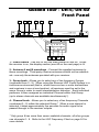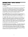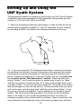
1
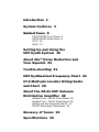
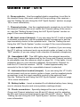
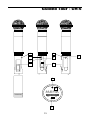
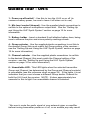
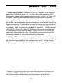
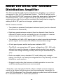
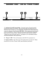
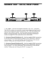
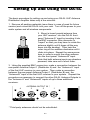
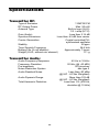
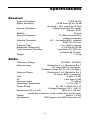
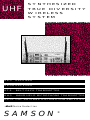
UHF
SYNTHESIZED
TRUE
DIVERSITY
WIRELESS
SYSTEM
UR-5
RECEIVER
UR-5D RECEIVER
UT-5
BELT PACK TRANSMITTER
UH-5
HAND-HELD MICROPHONE TRANSMITTER
DA-5L UHF ANTENNA DISTRIBUTION AMPLIFIER
•dbx® Noise Reduction
SAMSON
®
Introduction 1
System Features 3
Guided Tours 5
UR-5/UR-5D Front Panel 5
UR-5/UR-5D Rear Panel 8
UT-5 10
UH-5 13
Setting Up and Using the
UHF Synth System 16
About dbx® Noise Reduction and
Tone Squelch 20
Trouble-shooting 21
UHF Synthesized Frequency Chart 24
UT-5 Multi-pin Lavalier Wiring Guide
and Chart 25
About The DA-5L UHF Antenna
Distribution Amplifier 28
Guided Tour - DA-5L Front Panel 29
Guided Tour - DA-5L Rear Panel 30
Setting Up and Using the DA-5L 31
DA-5L Grounding Techniques 33
Glossary of Terms 34
Specifications 36
Introduction
Congratulations on purchasing the Samson UHF Synthesized True
Diversity Wireless System! Although this product is designed for easy
operation, we suggest you take some time out first to go through these
pages so you can fully understand how we’ve implemented a number of
unique features.
Every wireless system consists of at least two components—a transmitter and a receiver. The Samson UHF Synth System you have
purchased contains either our UT-5 belt-pack transmitter (for lavalier
microphone, headset microphone, and guitar applications) or our UH-5
hand-held microphone transmitter. The matching receiver is either our
UR-5 single diversity model (for reception of a single monophonic
signal), or our UR-5D dual diversity model (for reception of two monophonic signals or a stereo signal). Here’s an illustration that shows an
overview of our system design:
GROUP
INPUT
4
5
7
5
A
6
8
2
1
dbx
NOISE
REDUCTION
0
9
8
2
1
0
9
4
B
RF LEVEL
3
7
3
ANTENNA - A
UT-5
AF LEVEL
5
6
CHANNEL
4
6
3
Beltpack Transmitter
1
2
AVAILABLE
1
2
4
/
3
MUTE
5
4
SAMSON
7
5
3
AF LEVEL
2
8
1
POWER
UHF SYNTHESIZED DIVERSITY RECEIVER
9
0
10
UR-5
UHFSynth Series
OPEN
OPEN
SAMSON
UHFSynth Series
SAMSON
MPL2242
MPL2242
SAMSON
SERVO - 240
1
ANTENNA - B
Introduction
The concept behind a “true diversity” wireless system is that a single
chassis houses two discrete receivers (called “channel A” and “channel
B”) instead of one, with both tuned to the same frequency but with each
using an independent antenna. A built-in computer chip then continuously scans the two receivers and determines which one has the clearest and strongest reception, automatically (and silently) switching to that
channel. This allows you to maintain the wireless communication link
over a much broader area range than would be allowed by a single
receiver and also virtually eliminates interference and phase cancellation problems. In addition, our special circuitry, which utilizes the UHF
(Ultra High Frequency) band, delivers the highest-quality sound
available in any wireless system. Finally, the provision of dbx® noise
reduction* produces crystal-clear sound with minimized background
noise and hiss. Your UHF Synthesized True Diversity System may also
optionally include a DA-5L UHF Antenna Distribution Amplifier. For
more information on this device, see pages 28 - 33.
In this manual, you’ll find a more detailed description of the features of
this system, as well as a guided tour through all components, step-bystep instructions for setting up your system, trouble-shooting tips, wiring
diagrams and tables, a glossary of terms, and full specifications. You’ll
also find a warranty card enclosed—don’t forget to fill it out and mail it!
This will enable you to receive online technical support and will allow us
to send you updated information about these and other Samson products in the future.
SPECIAL NOTE: Should any component of your UHF Synthesized True
Diversity Wireless System ever require servicing, a Return Authorization
number (RA) is necessary. Without this number, the unit will not be
accepted. Please call Samson at 1-800-372-6766 for a Return
Authorization number prior to shipping your unit. Please retain the original packing material and, if possible, return the unit in its original carton
and packing materials.
* dbx is a registered trademark of Carillon Industries.
2
System Features
The Samson UHF Synthesized True Diversity System utilizes state-ofthe-art technology in wireless communications. Here are some of its
main features:
• 74 available channels organized in 10 different groups in both the
receiver and transmitter, with up to 11 channels available for simultaneous use. This makes our UHF Synth System the ideal choice in
multi-user environments such as stage productions and live band
performance. It is also specifically suited for systems that travel into
“hostile” RF environments (such as highly populated urban areas,
where large numbers of radio transmissions occur simultaneously
over broad bandwidth areas).
• The use of the UHF (Ultra High Frequency) band as opposed to VHF
(Very High Frequency), which yields better signal-to-noise ratio and
improved frequency response—in plain English, superior sound
quality. The UHF band is also considerably less crowded than VHF,
thus minimizing potential interference problems. In addition, our
special dielectric filtering circuitry (which, incidentally, is based upon
cellular phone technology) provides extra narrow bandwidths, thus
further reducing interference.
• True Diversity technology, which greatly extends the effective range
of the system and also virtually eliminates interference and phase
cancellation problems.
• Built-in dbx® noise reduction circuitry in both the transmitter and
receiver. This ensures clear, transparent sound with an absolute
minimum of background noise and hiss.
• A clear, easy-to-read visual display that shows continuous RF
(Radio Frequency) level (indicating the strength of the received signal) as well as AF (Audio Frequency) level. The RF level display also
shows the clearest frequency to use in crowded wireless environments.
• Balanced and unbalanced audio outputs on both the UR-5 and
UR-5D receivers, making them compatible with all types of external
audio mixers and amplifiers.
3
System Features
• The UT-5 and UH-5 transmitters both accept standard 9-volt
alkaline batteries, and the UR-5 and UR-5D receivers can accept
any AC power voltage from 100 - 250 volts, without the need to
change a voltage selector switch (our special current and voltage
sensing circuitry does the job automatically for you).
• Tuned coaxial antennas are included, with options for rear-mounting
or remoting if extended range is required.
• The UR-5D dual receiver actually contains two separate true
diversity receivers in a single chassis for the reception of two discrete monophonic signals or a stereo signal. It also provides an
option for output mixing, which combines the received signals from
both inputs into a single monophonic output—critical when using
audio mixers with limited numbers of channels.
• All components utilize an automatic tone squelch feature that
prevents the reception of unwanted signals.
• The UT-5 belt-pack transmitter is extremely light-weight (less than 4
ounces with a 9-volt battery installed) and is suited for a wide range
of lavalier and headset mics and instruments such as electric guitar
and bass. It also provides phantom powering, making it compatible
with professional condenser lavalier and headset microphones.
• The UH-5 hand-held microphone transmitter features an all-brass
housing painted with a durable epoxy base. A selection of mic
capsules are available, including:
Electro Voice 757 N/DYM Dynamic
Electro Voice 857 N/DYM Dynamic
Sennheiser MKE-4032 Condenser
Shure SM58 Dynamic
Shure SM87 Condenser
Shure SM85 Condenser
• Both the UT-5 and UH-5 transmitters provide “popless” muting,
which turns off the audio signal while leaving the carrier signal on.
• All components have rugged construction that ensures reliable
operation in even the most demanding performance environments.
4
Guided Tour - UR-5/UR-5D
Front Panel
2
4
3
GROUP
4
5
5
5
7
8
2
1
dbx
NOISE
REDUCTION
0
AF LEVEL
5
6
CHANNEL
6
3
A
6
9
8
2
1
0
9
4
B
RF LEVEL
3
7
3
ANTENNA - A
1
2
AVAILABLE
1
2
4
/
3
MUTE
5
4
AF LEVEL
SAMSON
7
5
3
2
1
6
2
8
1
POWER
UHF SYNTHESIZED DIVERSITY RECEIVER
ANTENNA - B
9
0
10
UR-5
UHFSynth Series
5a
A
B
RF LEVEL
1
2
3
AVAILABLE /
1
2
3
5
4
MUTE
4
5
AF LEVEL
5b 5d 5e 5c
1: Power switch - Use this to turn the main power on and off. When
the receiver is on, the display section (see #5 on the next page) is lit.
2: Antenna A and B mountings - Connect the supplied antennas to
these mountings. Third-party receiver antennas should not be substituted—use only the antennas provided with your receiver.
3: Group knob - Allows you to select any of ten frequency Groups
(numbered from 0 - 9). When using the Samson UHF Synth System in a
multiuser environment (that is, when there are two or more transmitters
and receivers in use at one location), all receivers must be set to the
same Group in order to avoid intermodulation distortion. Each individual
performer is then assigned an individual Channel within that Group
(up to eleven channels are available simultaneously*).
4: Channel knob - Allows you to select any of ten frequency Channels
(numbered 0 - 9) within the selected Group.* When a new channel is
selected, it takes approximately five seconds for audio signal to be
passed through to the receiver outputs.
* Only group 9 has more than seven available channels; all other groups
use channels 0 - 6. Refer to the UHF Frequency Chart on page 24 for
more details.
5
Guided Tour - UR-5/UR-5D
Front Panel
5: Display section - Shows you information about the current status of
your receiver.
5a: “A”/“B” LEDs - When signal is being received, one of these LEDs
(which shows you whether the “A” or “B” channel is currently being
used) will be lit. A computer chip inside the receiver constantly scans
the two and automatically selects whichever is receiving the strongest,
clearest signal. This “true diversity” switching is completely inaudible,
but it effectively increases overall range while virtually eliminating
potential interference and phase cancellation problems.
5b: “Available” LED - When lit, the selected Group and Channel (as
determined by the Group and Channel knobs) is available for use.
When off, the selected Group and Channel is unavailable and cannot be
used. See the reference chart on page 24 for more information.
5c: “Mute” LED - Lights to indicate the absence of carrier signal. As
described on page 20 of this manual, setting the UT-5 or UH-5 Audio
switch to the “on” position operates a tone squelch feature by causing
a 38.4 kHz signal to be added to the carrier. The illuminated word
“MUTE” in the UR-5 and UR-5D display is a visual representation of the
absence of this 38.4 kHz signal. When “MUTE” is lit, either the transmitter Audio switch is in the “off” position or the currently selected Group
and Channel do not match that of the transmitter.
5d: RF (Radio Frequency) Level display - This “ladder” display (similar to the VU bar meter used on audio devices) indicates the strength of
the UHF signal being received. When all five segments are lit, the
incoming signal is at maximum strength; when only the left-most segment is lit, the incoming signal is at minimum strength. If no segments
are lit, no signal is being received; check to ensure that the transmitter
and receiver are set to the same Group and Channel (see the “Troubleshooting” section on page 21 for more details).
6
Guided Tour - UR-5/UR-5D
Front Panel
5e: AF (Audio Frequency) Level display - This “ladder” display (similar to the VU bar meter used on audio devices) indicates the presence of
audio signal. When all five segments are lit, the outgoing signal is at
maximum strength; when only the left-most segment is lit, the outgoing
signal is at minimum strength. If no segments are lit, little or no signal is
being output; see the “Trouble-shooting” section on page 21 for more
details.
6: AF (Audio Frequency) Level - This knob determines the level of the
audio signal being output through both the balanced and unbalanced
output jacks on the rear panel.
NOTE: The UR-5D front panel (as shown below) is identical to that of the
UR-5 except that it provides two display sections and two group, channel, and AF level knobs—one for each of its two True Diversity receivers.
2
4
3
1
6
5
4
3
6
5
2
5a
GROUP
5
4
7
8
2
5
A
6
1
dbx
NOISE
REDUCTION
0
9
1
0
4
B
3
2
AVAILABLE
1
2
8
2
RF LEVEL
1
7
3
9
7
5
3
4
/
3
MUTE
5
4
2
8
1
POWER
5
10
4
6
7
3
8
2
1
UR-5D
UHFSynth Series
4
0
AF LEVEL
5
6
CHANNEL
GROUP
DUAL UHF SYNTHESIZED
DIVERSITY RECEIVER
9
0
AF LEVEL
SAMSON
AF LEVEL
5
6
CHANNEL
4
6
3
ANTENNA - A
9
5
A
6
8
2
1
0
9
4
B
RF LEVEL
3
7
3
1
2
AVAILABLE
1
2
4
/
3
MUTE
5
4
AF LEVEL
7
5
3
8
2
1
9
0
10
5a
A
1
2
AVAILABLE
1
2
5b 5d 5e 5c
B
RF LEVEL
5
3
4
/
3
MUTE
5
4
AF LEVEL
5b 5d 5e 5c
7
ANTENNA - B
Guided Tour - UR-5/UR-5D
Rear Panel
5
SAMSON MODEL No.UR-5
UHF SYNTHESIZED DIVERSITY RECEIVER
3
2
1
AC INPUT
POWER
RATING
120V~ 50 / 60Hz 11W
BALANCED
OUTPUT
-10dBm.600Ω
5
UNBALANCED
OUTPUT
-10dBv.5KΩ
(120V-240V VOLTAGE SENSING)
SAMSON TECHNOLOGIES CORP.
HICKSVILLE, NEW YORK, U.S.A.
1: AC input - Connect the supplied standard 3-pin “EEC” plug here.
The UR-5 and UR-5D both contain automatic current and voltage
sensing circuitry and so can accept any mains current from 100 - 250
volts without the need to set a selector switch.
2: Balanced output* - Use this electronically balanced low impedance
(600 Ohm) XLR jack when connecting the UR-5 or UR-5D to professional (+4) audio equipment. Pin wiring is as follows:
3 - SIGNAL
+
1 GROUND
2 + SIGNAL
* If required, both the balanced and unbalanced outputs can be used
simultaneously.
8
Guided Tour - UR-5/UR-5D
Rear Panel
3: Unbalanced output* - Use this unbalanced high impedance (5K
Ohm) 1/4” jack when connecting the UR-5 or UR-5D to consumer (-10)
audio equipment. Wiring is as follows:
+ SIGNAL
+ SIGNAL
GROUND
GROUND
4: Output Mixing switch (UR-5D receiver only) - When on, the outputs
from both receivers are mixed together equally into a single monophonic
signal which appears at both sets of balanced and unbalanced outputs.
5: Rear-mount antenna knockouts - The receiver antennas can
optionally be mounted at these areas of the rear panel. Contact
Samson Technologies for information about our rear-panel antenna
mounting kit.
3
2
5
SAMSON MODEL No.UR-5D
UHF SYNTHESIZED DIVERSITY RECEIVER
BALANCED
OUTPUT
-10dBm.600Ω
UNBALANCED
OUTPUT
-10dBv.5KΩ
4
1
BALANCED
OUTPUT
-10dBm.600Ω
AC INPUT
POWER
RATING
3
2
120V~ 50 / 60Hz 17W
5
UNBALANCED
OUTPUT
-10dBv.5KΩ
(120V-240V VOLTAGE SENSING)
OUTPUT MIXING
ON
OFF
SAMSON TECHNOLOGIES CORP.
HICKSVILLE, NEW YORK, U.S.A.
RECEIVER 1
RECEIVER 2
* If required, both the balanced and unbalanced outputs can be used
simultaneously.
9
Guided Tour - UT-5
2
3
4
AUDIO
BATT
5
ANT
INPUT
OFF
ON
POWER
ON
OFF
1
5
INPUT
Beltpack Transmitter
UT-5
SAMSON
8
10
7
6
9
4
5
2
1
0
4
6
3
7
3
8
2
11
6
7
8
1
9
5
0
9
12
SAMSON
GROUP
CHANNEL
MIC LEVEL
UNAVAILABLE
INPUT
INST LEVEL
INST
4
5
2
1
0
4
6
3
9
7
3
8
2
5
6
7
8
1
0
9
MIN
MIC
MAX
10
MIN
MAX
Guided Tour - UT-5
1: Power on-off switch* - Use this to turn the UT-5 on or off (to
conserve battery power, be sure to leave it off when not in use).
2: Six-pin input connector - Connect your input device (lavalier mic,
headset mic or instrument cable) here, using the supplied six-pin
connector. A wiring diagram and chart (showing connections for many
popular lavalier and headset mics) is presented on pages 25 - 27.
3: Battery LED - This LED is an indicator of battery strength. If the
battery is sufficiently strong, when the UT-5 is first powered on, this LED
will light for about two-tenths of a second and then go off.** When battery voltage is low, this LED lights steadily, indicating that the battery
needs to be replaced.
4: Audio on-off switch - When set to the “on” position, audio signal is
transmitted. When set to the “off” position, the audio signal is muted.
Because the carrier signal remains during muting, no “pop” or “thud” will
be heard. Note that turning this off does not turn off the transmitter
power—it is simply a way to temporarily mute the transmission of audio
signal. If you don’t plan on using the transmitter for extended periods,
turn off the transmitter power by using the power on-off switch (see #1
above). As described on page 20 of this manual, setting the UT-5 Audio
switch to the “on” position operates a tone squelch feature by causing
a 38.4 kHz signal to be added to the carrier. The illuminated word
“MUTE” in the UR-5 and UR-5D display is a visual representation of the
absence of this 38.4 kHz signal. When “MUTE” is lit, either the transmitter Audio switch is in the “off” position or the currently selected Group
and Channel do not match that of the transmitter.
5: Antenna - Connect the supplied transmitter antenna to this mounting. Replacement antennas are available from Samson Technologies if
required.
* Be sure to mute the audio signal at your external mixer or amplifier
before turning transmitter power on or off, or an audible pop may result.
** However, if you turn on the UT-5 within five seconds of turning it off,
the Battery LED will not light. We recommend that you always leave at
least five seconds between turning off and turning on the UT-5.
11
Guided Tour - UT-5
6: Group selector - Use the supplied plastic screwdriver to set this to
the desired Group (this must match the Group setting of the receiver—
see the “Setting Up and Using the UHF Synth System” section on page
16 for more information).
7: Channel selector - Use the supplied plastic screwdriver to set this to
the desired Channel (this must match the Channel setting of the receiver—see the “Setting Up and Using the UHF Synth System” section on
page 16 for more information).
8: Mic level control (trimpot) - If you are using the UT-5 with a lavalier
or headset microphone, use the supplied plastic screwdriver to set this
input sensitivity control to the optimum level. See the “Setting Up and
Using the UHF Synth System” section on page 16 for more information.
9: Input switch - Set this to either the “INST” position (if you are using
the UT-5 with an instrument such as an electric guitar or bass) or to the
“MIC” position (if you are using it with a lavalier or headset microphone).
10: Unavailable LED - This LED lights when the selected transmitter
Group and Channel (as determined by the Group and Channel controls)
is unavailable (see the reference chart on page 24). If this lights, it is an
indication that you must choose a different Group and/or Channel for
both the UT-5 and the receiver. NOTE: It takes approximately two
seconds for this to light if an unavailable channel is selected.
11: Instrument level control (trimpot) - If you are using the UT-5 with
an instrument such as an electric guitar or bass, use the supplied plastic
screwdriver to set this input sensitivity control to the optimum level.
See the “Setting Up and Using the UHF Synth System” section on page
16 for more information.
12: Battery holder - Insert a standard 9-volt alkaline battery here, being
sure to observe the plus and minus polarity markings shown.
13: Plastic screwdriver - Specially designed for use in setting the
Group and Channel selectors (see #6 and #7 above) and for adjusting
the Mic and Instrument level trimpots (see #8 and #11 above). See the
“Setting Up and Using the UHF Synth System” section on page 16 for
more information.
12
Guided Tour - UH-5
1
1
POWER
5
0
6
9
8
7
3
2
4
1
5
0
UNAVAILABLE
4
1
OFF
MIN MAX
8
7
- +
3
8
BATT
dbx
NR
SAMSON
UHF SYNTHESIZED
WIRELESS MICROPHONE
UH-5
FCC ID CCRUH-5
SAMSON
MADE IN JAPAN
OFF
ON
AUDIO
7
13
MIC
LEVEL
ON
6
6
9
3
3
PULL
TO
OPEN
2
5
GROUP CHANNEL
4
2
Guided Tour - UH-5
1: Power on-off switch* - Use this to turn the UH-5 on or off (to
conserve battery power, be sure to leave it off when not in use).
2: Mic level control (trimpot) - Use the supplied plastic screwdriver to
set this to the optimum microphone output level. See the “Setting Up
and Using the UHF Synth System” section on page 16 for more
information.
3: Battery holder - Insert a standard 9-volt alkaline battery here, being
sure to observe the plus and minus polarity markings shown.
4: Group selector - Use the supplied plastic screwdriver to set this to
the desired Group (this must match the Group setting of the receiver—
see the “Setting Up and Using the UHF Synth System” section on page
16 for more information).
5: Channel selector - Use the supplied plastic screwdriver to set this
to the desired Channel (this must match the Channel setting of the
receiver—see the “Setting Up and Using the UHF Synth System”
section on page 16 for more information).
6: Unavailable LED - This LED lights when the selected transmitter
Group and Channel (as determined by the Group and Channel controls)
is unavailable (see the reference chart on page 24). If this lights, it is an
indication that you must choose a different Group and/or Channel for
both the UH-5 and the receiver. NOTE: It takes approximately two
seconds for this to light if an unavailable channel is selected.
* Be sure to mute the audio signal at your external mixer or amplifier
before turning transmitter power on or off, or an audible pop may result.
14
Guided Tour - UH-5
7: Audio off-on switch - When set to the “on” position, audio signal is
transmitted. When set to the “off” position, the audio signal is muted.
Because the carrier signal remains during muting, no “pop” or “thud” will
be heard. Note that turning this off does not turn off the transmitter
power—it is simply a way to temporarily mute the transmission of audio
signal. If you don’t plan on using the transmitter for extended periods,
turn off the transmitter power by using the power on-off switch (see #1 on
the previous page). As described on page 20 of this manual, setting the
UT-5 Audio switch to the “on” position operates a tone squelch feature
by causing a 38.4 kHz signal to be added to the carrier. The illuminated
word “MUTE” in the UR-5 and UR-5D display is a visual representation
of the absence of this 38.4 kHz signal. When “MUTE” is lit, either the
transmitter Audio switch is in the “off” position or the currently selected
Group and Channel do not match that of the transmitter.
8: Battery LED - This LED is an indicator of battery strength. If the battery is sufficiently strong, when the UH-5 is first powered on, this LED will
light for about two-tenths of a second and then go off.* When battery
voltage is low, this LED lights steadily, indicating that the battery needs
to be replaced.
* However, if you turn on the UH-5 within five seconds of turning it off,
the Battery LED will not light. We recommend that you always leave at
least five seconds between turning off and turning on the UH-5.
15
Setting Up and Using the
UHF Synth System
The general procedure for setting up and using your UHF Synth System
is basically the same regardless of the particular components you are
using (i.e. UT-5 or UH-5; UR-5 or UR-5D):
1. Remove all packing materials (save them in case of need for future
service) and mount the supplied “A” and “B” antennas to your receiver
by inserting the BNC connector and twisting clockwise until snug.
INPUT
Beltpack Transmitter
UT-5
OPEN
OPEN
OPEN
SAMSON
UHFSynth Series
1a. If you are using the UT-5 beltpack transmitter, connect its antenna
by inserting the wire and turning it clockwise until snug and then make
the physical connection between its 6-pin plug and the lavalier microphone, headset microphone or instrument cable you are using (be sure
to correctly set the “Mic/Instrument” switch). Because the 6-pin
plug is “keyed,” you’ll need to rotate it a certain way to get it to “mate”
with the connector mounted on the UT-5; then push straight down until
you hear a click. To remove the 6-pin connector, lift up the outer sleeve
and pull straight out (do not use force!). We recommend that you never
pull on the wire, only the plug itself (with the outer sleeve lifted). If you
are using a lavalier microphone, correct placement is critical to sound
quality. We recommend that you place it as shown in the illustration
above—as close to your mouth as possible but off to one side (to
minimize nasality) and unobstructed by clothing. Bear in mind also that
omni-directional microphones (mics which pick up signal from all direc16
Setting Up and Using the
UHF Synth System
tions) are more prone to feedback problems than unidirectional (cardioid
or supercardioid) ones; in general, you can avoid feedback by taking
care not to use any microphone directly in front of a PA speaker (if this
is unavoidable, you can try using an equalizer to attenuate those high
frequencies which are causing the feedback “squealing”).
2. Place a fresh 9-volt alkaline battery (not supplied) into your UT-5 or
UH-5 transmitter, taking care to observe the polarity markings. We
recommend the Duracell MN 1604 type or equivalent. We do not
recommend the use of rechargeable Ni-Cad batteries because they do
not supply adequate current for any significant time period. For the
moment, leave the transmitter turned off.
3. Make the physical cable connections between the output of your
UR-5 or UR-5D receiver (using either the balanced or unbalanced
jacks)* and the input of your amplifier or mixer. If you are using
professional (+4) equipment, the balanced jack is preferable since it will
deliver an electromagnetically cleaner signal. Leave the amplifier
(and/or mixer) off at this time.
4. Connect the supplied 3-pin “EEC” plug into the UR-5 or UR-5D rear
panel AC connector and plug the other end into any grounded AC
socket.
5. Turn the AF Level knob on the UR-5 receiver (or both AF Level
knobs on the UR-5D receiver) completely counterclockwise (to the “0”
position) and depress the power switch to turn the unit on. The display
section will light up.
6. Before utilizing the UR-5 or UR-5D Group and Channel knobs to
select a frequency, determine how many transmitters and receivers you
will be using in one location. As shown in the chart on page 24, Groups
0 through 8 provide seven available Channels each (0 through 6), while
Group 9 provides eleven available Channels (0 through 9, plus Group 7,
Channel 5). When two or more transmitters and receivers are being
* If required, both the balanced and unbalanced outputs can be used
simultaneously.
17
Setting Up and Using the
UHF Synth System
used at the same location, all devices must be set to the same Group
(though each will use its own Channel) or intermodulation noise may
occur. If you are using the UR-5D receiver for the reception of a stereo
signal (or for the reception of two simultaneous monophonic signals),
both sides (Receiver 1 and Receiver 2) must be set to the same Group.
If you are only using a single transmitter and receiver, you can select any
Group and available Channel with a sufficiently strong signal (see #6
below). Start with Group 0 and scan through all available Channels
while observing the RF Level display in the receiver. If any segments
glow with the transmitter off, the selected Channel may be receiving
interference and is probably unsuitable for use (one segment glowing is
insignificant). Select a Group that has the greatest number of suitable
Channels (that is, Channels where no segments light or glow with the
transmitter off).* When you have decided which Group and Channel
you wish to utilize, use the supplied plastic screwdriver to set the same
Group and Channel on the appropriate UT-5 or UH-5 transmitter.
7. Turn on the power to the UT-5 or UH-5 transmitter (using its Power
on-off switch) and observe the RF Level display in the UR-5 or UR-5D
receiver; all segments should light up. When first setting up the UHF
Synth System in a new environment, it’s always a good idea to do a
walkaround while experimenting with different Group and Channel
settings—you may find that some cause more RF Level segments to
light up than others (the more segments light, the stronger the signal).
Always pick the Group that has the greatest number of clear Channels
and the Channel providing the strongest signal. Note that whenever a
new channel is selected, it takes approximately five seconds for audio
signal to be passed through to the receiver outputs.
8. Once you’ve settled on your Group and Channel assignments, it’s
time to set the audio levels. If you are using the UH-5 transmitter or the
UT-5 transmitter with a connected lavalier or headset microphone, speak
or sing into the mic at a normal performance level while slowly raising
the equivalent AF Level knob on the receiver to a level of approximately
“8.”. Observe the receiver’s AF level display as you do so; one or more
* If your installation requires more than seven simultaneous Channels,
you’ll have to use Group 9.
18
Setting Up and Using the
UHF Synth System
segments should light up. If you are using the UT-5 transmitter with a
connected instrument, play the instrument at normal performance level
while slowly raising the equivalent AF Level knob on the receiver to a
level of approximately “8”; again, one or more segments in the AF Level
display should light up as you do so.
9. Temporarily mute the audio signal by placing the UT-5 or UH-5
Audio switch to the “off” position. Then turn on your connected amplifier
and/or mixer but keep its volume all the way down. Next, unmute the
audio signal (by placing the UT-5 or UH-5 Audio switch to the “on” position) and speak into the microphone (or play the instrument) at a normal
performance level. Slowly raise the volume of your amplifier/mixer until
the desired level is reached. If you hear distortion, use the supplied
plastic screwdriver to turn the Mic or Instrument control (trimpot) on the
transmitter slowly counterclockwise until the distortion disappears. If
you hear a weak, noisy signal, do the reverse: use the supplied plastic
screwdriver to turn the Mic or Instrument control (trimpot) on the transmitter slowly clockwise until the signal reaches a good level.
10. If you are using the UR-5D receiver and you wish to keep the two
output signals separate, make sure the Output Mixing switch on the rear
panel is in the “Off” position. If you wish to mix the two signals together,
set the switch to the “On” position; the two output signals will then be
mixed together and routed to all four output jacks.
The basic rule of thumb for wireless audio systems is to always try to
minimize the distance between transmitter and receiver as much as
possible and also to try to maintain “line of sight” between the two (that
is, the person using the transmitter should be able to see the receiver
antennas). In fixed installations such as A/V or corporate conference
rooms or for extended range applications (where the transmitter and
receiver are more than 150 feet apart), it may be desirable to remote the
receiver antennas so that the strongest possible signal is received from
the planned transmission points. This can be accomplished by using
standard BNC connections and 50 ohm coaxial cabling that is suitable
for up to 1 gigaHertz bandwidth usage. For more information, see the
“Trouble-shooting” section on page 21.
19
About dbx® Noise Reduction
and Tone Squelch
About dbx® Noise Reduction:
All the components in the Samson UHF Synth System utilize dbx® noise
reduction so as to ensure the highest fidelity sound with an absolute
minimum of background noise and hiss. dbx® is a companding system;
that is, the signal being transmitted has its dynamic range compressed
and its high frequencies boosted (this process is known as pre-emphasis
encoding), and the signal being received has its dynamic range expanded and high frequencies attenuated in an exactly opposite way (this
process is known as de-emphasis decoding). The pre-emphasis
encoding process is automatically carried out by the UT-5 and UH-5
transmitters and the de-emphasis decoding process is automatically
carried out by the UR-5 and UR-5D receivers. For this reason, you must
use these matched components in order for the noise reduction to work
as intended.
Note also that the headroom available from using the dbx noise
reduction system typically exceeds the peak limit of the UR-5 and UR-5D
Audio Level meter by approximately 20 dB. Therefore, you should
experiment (by listening or other method) in order to find the proper
signal level. In many cases, the meter will be well beyond its peaked or
pinned reading without incurring any distortion of signal.
About Tone Squelch:
The Samson UHF Synth System also provides an automatic tone
squelch feature that effectively prevents the UR-5 and UR-5D receivers
from passing unwanted audio signal generated by outside sources.
Here's how it works: Both the UT-5 and UH-5 transmitters add a supersonic 38.4 kHz tone to all audio signals they transmit. The UR-5 and
UR-5D receivers will refuse to pass through any received audio signal
that does not contain this tone (for example, radio conversation between
passing taxicab drivers).
20
Trouble-shooting
Problem: No sound
Solution: When working correctly, both the RF Level and AF Level
meter displays in the UR-5 or UR-5D receiver should be lit when signal
is present. If they aren’t, follow these step-by-step troubleshooting suggestions to identify the problem. If the answer to any of these questions
is “no,” you’ve probably located the difficulty. If both the RF Level and
AF Level displays are lit, you can skip ahead to questions 9, 10 and 11.
1. Are your transmitter and receiver both powered on? When first
powered on, the “Battery” LED in the UT-5 and UH-5 will light for twotenths of a second and then go off, and one or more segments of the
UR-5 or UR-5D RF Level display will be continuously lit, indicating
carrier transmission.
2. Is the battery in your transmitter fresh? (If not, the “Battery” LED will
be lit bright red).
3. If you’re using the UT-5 belt-pack transmitter, is the “INST/MIC” input
switch set correctly? If so, is the physical lavalier, headset or instrument
cable connection correctly wired and secure? If you’re using the UT-5
for electric guitar or bass, check to see that the instrument’s settings are
correct (i.e. master volume up, etc.).
4. Is the “MUTE” LED on the receiver off and is the “Audio” switch on
the transmitter set to “On”?
5. If you are using the UH-5 or the UT-5 with a lavalier or headset
microphone, is the Mic level control (trimpot) on the transmitter set to a
value greater than 0? If you are using the UT-5 with an instrument, is
the Instrument level control (trimpot) on the transmitter set to a value
greater than 0?
6. Is the AF Level knob on the receiver set to a value greater than 0?
7. Are your transmitter and receiver both set to the same Group and
Channel number? (If so, one or more LEDs in the “RF Level” display
will be lit.)
21
Trouble-shooting
8. Is the “Available” LED on the receiver lit and is the “Unavailable” LED
on the transmitter off?
9. Is the cable connection between the receiver output and your
mixer/amplifier input secure?
10. Is your mixer/amplifier system powered on and is its level control or
fader up and unmuted?
11. If you’re using a mixer, are all channels out of solo mode?
If the answer to all these questions is “yes” and you still hear no sound,
call Samson Technical Support at 1-800-372-6766. Bear in mind also
that both the receiver and transmitter in the UHF Synth System contain
delicate components called crystals. As their name implies, these are
subject to damage when the unit is subjected to extreme stress (such as
being dropped from a significant height), so treat your receiver and
transmitter with the kind of TLC you normally reserve for loved ones!
Problem: Distorted sound
(Cross-modulation interference)
Solution:
Try using a different Group and/or Channel. If two or
more users are connected to the system (using multiple transmitters and
receivers at the same location), they must all be transmitting and receiving on the same Group, with different channels selected for each user.
Also, if the UR-5 or UR-5D receiver is mounted in a rack near equipment
such as computers, hard drives, or electronic keyboards or tone generators, intermodulation noise can occur. Try moving the receiver 5 or 6
feet away from such equipment—if the noise disappears, you’ve located
(and solved) the problem.
22
Trouble-shooting
Problem: Sound fades as performer moves
around (sound dropout)
Solution:
Try relocating the transmitter and/or receiver. In general,
it’s best to minimize the distance between the two and also to try to
keep a clear “line of sight,” so that the person wearing or using the
transmitter can always see the receiver. If necessary, try relocating
the receiver antennas to either the rear panel (contact Samson
Technologies for details about our rear panel mounting kit) or remote
them some distance from the receiver, using 50 ohm coaxial cable
suitable for up to 1 gigaHertz bandwidth (the lower the capacitance of
the cable, the further you can remote the antennas).
23
UHF Synthesized Frequency
Chart
SAMSON UHF SYNTHESIZED FREQUENCY CHART
C
R
O
U
P
0
1
2
3
4
5
6
7
8
9
2
A
N
4
N
5
E
L
7
8
9
*
805.875 804.750 802.375 800.500 799.500 798.000 797.750
NA
NA
NA
NA
805.750 804.625 802.250 800.375 799.375 797.875 797.625
NA
NA
NA
NA
805.125 804.000 801.625 799.750 798.750 797.250 797.000
NA
NA
NA
NA
805.000 803.875 801.500 799.625 798.625 797.125 796.875
NA
NA
NA
NA
804.500 804.250 803.250 800.875 799.125 796.625 796.250
NA
NA
NA
NA
804.375 804.125 803.125 800.750 799.000 796.500 796.125
NA
NA
NA
NA
803.000 802.625 800.125 798.375 796.000 795.000 794.750
NA
NA
NA
NA
802.875 802.500 800.000 798.250 795.875 794.875 794.625
NA
NA
NA
NA
805.375 802.125 799.875 797.500 795.750 794.500 794.125
NA
NA
NA
NA
0
G
H
1
3
6
805.500 805.250 804.875 804.000 802.250 801.750 800.125 799.375 797.375 796.000 *G7CH5
Note that Group 9 supports up to eleven simultaneous channels. This is
accomplished by making all ten channel locations (0 through 9) available plus the use of Group 7, Channel 5 as a compatible “eleventh”
channel.
24
UT-5 Multi-pin Lavalier
Wiring Guide
The UT-5 transmitter can be used with a wide range of lavalier microphones, headset microphones and instruments (such as electric guitar
or bass). The illustration below shows the wiring connections for its
multi-pin input connector:
LARGE OUTER
STRAIN RELIEF
SLEEVE
SMALL DIAMETER LAVALIER WIRE
SMALL INNER
STRAIN RELIEF
PLUG CASE
Samson Technologies offers the following pre-wired input accessory
cables for the UT-5:
Part Number
Description
————————————————————————————————
GC-1
Instrument cable, suitable for use with electric guitar or
bass, etc. Terminates at standard 1/4” phone plug.
MC-1
Low-impedance microphone cable, suitable for use with
most dynamic and condenser microphones.
Terminates at standard 3-pin XLR plug.
We offer the following lavalier microphones, available pre-wired for use
with the UT-5: Sony ECM-44, ECM-55, ECM-77; Sennheiser MKE-2;
Audio Technica 831C.
We also offer the following headsets, available pre-wired for use with
the UT-5: AKG C-410; Audio-Technica AT-71B; and Countryman
IsoMax.
For information about connecting other lavalier microphones and
headsets to the UT-5, refer to the chart on the following two pages.
25
UT-5 Multi-Pin Wiring Chart
Manufacturer
Model No.
Pin 1
Pin 2
———————————————————————————————————
AKG
C409 Horn Mic
Shield
White/Clear
AKG
C410 Headset
Shield
White/Clear
Audio Technica
AT-831
Red (2x)
Yellow (2x)
Audio Technica
ATM-71
Red (2x)
Yellow (2x)
Audio Technica
ATM-75 Headset
Red (2x)
Yellow (2x)
Audio Technica
PRO8 Headset
N/C
Red (2x)
Audio Technica
MT-350
15KΩ Resistor
to pin 2
White/Clear
Countryman
Isomax Headset
Red
Green
PSC
PSC/P6
Red
White
Samson
ECM-40
15KΩ Resistor
to pin 2
White/Clear
Sanken
COS-11PT
Black
White/Clear
Sennheiser
MKE-2
Red
Blue
Sennheiser
MKE-2R
(Red Dot)
Red
8.2 KΩ Resistor
to pin 1
Sennheiser
MKE-40
Red
Blue
Shure
SM10A
N/C
Red
Sony
ECM-44
Red
White/Clear
Sony
ECM-55
Red
White/Clear
Sony
ECM-77
Red
White/Clear
Sony
ECM-144
15KΩ Resistor
to pin 2
White/Clear
High Impedance
Guitar
GC-1/P6
N/C
N/C
Low Impedance
Guitar
MC-1/P6
N/C
N/C
Keyboards
GC-1/P6
Pin Information
26
N/C
N/C
+9 VDC
Audio
UT-5 Multi-Pin Wiring Chart
Pin 3
Pin 4
Pin 5
Pin 6
———————————————————————————————————
N/C
N/C
N/C
Red
N/C
N/C
N/C
Red
15KΩ Resistor
to pin 2
N/C
N/C
Shield
15KΩ Resistor
to pin 2
N/C
N/C
Shield
15KΩ Resistor
to pin 2
N/C
N/C
Shield
N/C
N/C
N/C
Yellow (2x)
Shield
N/C
N/C
N/C
Shield
Jumper-to-pin 2
N/C
Jumper-to-pin 6
Shield
N/C
N/C
Jumper-to-pin 2
Shield
N/C
N/C
N/C
Shield
Jumper-to-pin 2
N/C
Jumper-to-pin 6
Shield
Jumper-to-pin 2
N/C
Jumper-to-pin 6
Shield
N/C
N/C
N/C
Blue & Shield
Jumper-to-pin 2
N/C
Jumper-to-pin 6
Shield
N/C
N/C
N/C
Black & Shield
Jumper-to-pin 2
N/C
N/C
Shield
Jumper-to-pin 2
N/C
N/C
Shield
Jumper-to-pin 2
N/C
N/C
Shield
N/C
N/C
N/C
Shield
N/C
Audio
N/C
Shield
Jumper-to-pin 2
N/C
XLR-2
(Audio)
XLR-1 & 3
(GND)
N/C
Audio
N/C
Shield
Ground
Bipolar
Hi-Z
Audio
Mic
Lo-Z
Ground
Unipolar
NOTES:
• Resistors in plugs should be SMD (Surface Mount Device) or miniature type.
• Users of Sennheiser MKE-40: Add a 100pF capacitor between pin 2 and pin 5 only if necessary.
For more information, call Samson Technical Support at 1-800-372-6766.
27
About The DA-5L UHF Antenna
Distribution Amplifier
The Samson DA-5L UHF Antenna Distribution Amplifier is an optional
component of the UHF Synthesized System. The DA-5L allows up to
four UR-5 or UR-5D UHF receivers to share the same pair of antennas.*
It facilitates faster, more compact setups by reducing the number of
antennas from eight to two while increasing the transmission range by
adding 6 dB of RF gain for a stronger, quieter signal.
DA-5L features include:
• Two phantom powered front-panel antenna inputs (one for channel
A and one for channel B).
• Eight rear-panel antenna outputs (four for channel A and four for
channel B) which can be connected to up to four pairs of receiver
antenna inputs using the supplied BNC connector kit.
• The addition of 6 dB of RF signal gain in order to provide a stronger,
quieter signal and increase the effective transmission range.
• A front-panel power switch and power indicator LED.
• The DA-5L can accept any AC power voltage from 100 - 250 volts,
without the need to change a voltage selector switch (our special
current and voltage sensing circuitry does the job automatically for
you).
• Rack-mountable in any standard 19" rack (taking only a single
space), the DA-5L can easily be integrated into any traveling or fixed
installation audio system.
• Rugged construction that ensures reliable operation in even the
most demanding performance environments.
* Note that, even though the DA-5L allows multiple receiver antenna
inputs to be shared, each receiver (and accompanying transmitter) in
your UHF Synthesized True Diversity wireless system must still be tuned
to a discrete channel for multi-user operation.
28
Guided Tour - DA-5L Front Panel
2
1
3
1
SAMSON
ANTENNA - A
INPUT 50 Ω
POWER
UHF ANTENNA DISTRIBUTION AMPLIFIER
ANTENNA - B
INPUT 50 Ω
DA-5
UHF Synth Series
1: Antenna A and B mountings - Connect a pair of tuned coaxial
antennas to these mountings. Use the antennas provided with your
Samson UHF receiver, or, if unavailable, substitute the following antennas only: Samson Part Number ANT 800. Third-party antennas should
not be substituted. These antenna mountings are phantom powered;
take care not to short them. See the section in this manual entitled
“Setting Up and Using the DA-5L” (on page 31) for information about
antenna installation and positioning.
2: “Power” LED - This is lit whenever the DA-5L is powered on.
3: Power switch - Use this to turn the main power on and off. When
the DA-5L is on, the “Power” LED (see #2 above) will be lit.
29
Guided Tour - DA-5L Rear Panel
3
1
2
1
ANTENNA OUTPUT 50 Ω
2
3
4
SAMSON
UHF ANTENNA DISTRIBUTION AMPLIFIER
MODEL No.DA-5H
4
Frequency range:947MHz to 952MHz
ANTENNA OUTPUT 50 Ω
3
2
1
POWER RATING
DISTRIBUTOR B
SAMSON TECHNOLOGIES CORP.
HICKSVILLE, NEW YORK, U.S.A.
120V~ 50/60Hz 3W
(120V TO 240V VOLTAGE SENSING)
AC INPUT
MADE IN JAPAN
DISTRIBUTOR A
1: AC input - Connect the supplied standard 3-pin “EEC” plug here.
The DA-5L contains an automatic current and voltage sensing circuitry
and so can accept any mains current from 100 - 250 volts without the
need to set a selector switch. The AC outlet used for powering the
DA-5L must be grounded. See the “DA-5L Grounding Techniques”
section on page 33 of this manual for more information.
2: Antenna Output (Distributor A) - Use the supplied BNC connectors
to connect each of these antenna outputs to the “Antenna A” inputs of
your receivers. For more information, see the section in this manual
entitled “Setting Up and Using the DA-5L” (on page 31).
3: Antenna Output (Distributor B) - Use the supplied BNC connectors
to connect each of these antenna outputs to the “Antenna B” inputs of
your receivers. For more information, see the section in this manual
entitled “Setting Up and Using the DA-5L” (on page 31).
30
Setting Up and Using the DA-5L
The basic procedure for setting up and using your DA-5L UHF Antenna
Distribution Amplifier takes only a few minutes:
1. Remove all packing materials (save them in case of need for future
service) and mount the DA-5L into your rack. Turn off the power to your
audio system and all wireless components.
2. Mount a tuned coaxial antenna from
your UHF receiver* into the DA-5L frontpanel “Antenna-A” input by inserting it into
the BNC connector (this connector is
“keyed” so that you may have to rotate the
antenna slightly until it drops all the way
down into the seating). Then twist the
outer ring of the antenna clockwise until it
clicks into place. Repeat the same procedure in order to mount the other antenna
into the front-panel “Antenna-B” input.
Note that both antenna inputs are phantom
powered; take care not to short them.
3. Using the supplied BNC connectors, make a connection between the
rear-panel Antenna Output 1 (Distributor A) and the “Antenna A” input
of the first UHF receiver in your system. Then make a connection
between the rear-panel Antenna Output 1 (Distributor B) and the
“Antenna B” input of the first UHF receiver in your system. Repeat this
procedure as necessary to connect the other DA-5L Antenna Outputs to
the “Antenna A” and “Antenna B” inputs of up to three additional
receivers.
4
ANTENNA OUTPUT 50 Ω
3
2
1
DISTRIBUTOR A
* Third-party antennas should not be substituted.
31
Setting Up and Using the DA-5L
If necessary, longer runs of standard low-capacitance (50-ohm) coaxial
cabling with BNC connectors can be substituted for the supplied cables.
Note that, even though the DA-5L allows receiver antenna inputs to
be shared, each receiver (and accompanying transmitter) in your
system must still be tuned to a discrete channel for multi-user
operation.
4. Connect the supplied 3-pin “EEC”
plug to the rear panel AC connector and
plug the other end into any grounded AC
socket (see the “DA-5L Grounding
Techniques” section on page 33).
Then depress the front-panel power
switch to turn the unit on. The “Power”
LED will light up.
5. Turn on the power first to all connected wireless components and
then to your audio system. Now we recommend you do a walkaround in
order to make sure that coverage is provided for your entire performance
area. With all transmitters unmuted, and the level of your audio system
set as before, have an assistant walk through the entire area that will
need to be covered while speaking, singing, or playing into each transmitter at a normal performance level. The presence of the DA-5L should
serve to increase the effective transmission range within your system—if
you do find that any new “dead spots” result instead, try changing the
angle of the DA-5L antennas. The basic rule of thumb for all wireless
audio systems is to always try to minimize the distance between transmitter and receiver as much as possible and also to try to maintain “line
of sight” between the two (that is, the person using the transmitter
should be able to see the receiver antennas). The idea is to ensure that
the strongest possible signal is received from all planned transmission
points. In fixed installations such as A/V or corporate conference rooms
or for extended range applications (where the transmitters and receivers
are more than 150 feet apart), it may be desirable to remote the DA-5L
antennas altogether by using standard BNC connectors and 50 ohm
coaxial cabling that is suitable for up to 1 gigaHertz bandwidth usage.
If you have followed all the steps above and are still experiencing difficulties, call Samson Technical Support (1-800-372-6766) between 9 AM
and 5 PM EST.
32
DA-5L Grounding Techniques
The DA-5L contains a switching power supply that will add an audible
hum to your audio signal if the unit is not plugged into a properly
grounded three-pin AC socket. Unless you’re using a “star ground
network” (see below), you must not use an adapter to lift the ground
from the DA-5L AC cable.
If the DA-5L is correctly connected to a grounded three pin socket and
you still experience hum or buzz when using it with other audio devices,
there's a simple test to determine the source of the problem: with all
devices powered on and connected with audio cabling, physically
remove each device, one by one, from the rack. If the hum disappears
when a particular device is removed, you'll know that that device is the
culprit. If the offending device uses a two-prong plug (or an external
two-prong AC/DC adapter), you can try reversing the plug in the socket.
If that doesn’t work, you may need to physically ground that device’s
chassis by connecting a wire (called a strap) from it to a grounded piece
of metal such as rack ears. Some pieces of equipment have a screwtype ground post to which the strap can be connected; if not, you can
attach some kind of metallic binding post to the case itself.
In addition, you can minimize possible interference by planning your RF
antenna, audio, electrical, and computer cable runs so that they are as
far apart from one another as possible and so they don’t run parallel to
one another. If they have to cross, try to ensure that they do so at a 90°
angle (that is, perpendicular to one another). In particular, try to keep
audio cabling away from external AC/DC adapters
If you’re using the DA-5L in a fixed installation, you may want to invest
the time and money into creating a star ground network for all your
audio devices. This is by far the best technique for avoiding grounding
problems. It involves using a formidable ground source such as a cold
water pipe or a copper spike driven into the earth. A thick grounding
cable is connected to that source and is then brought to a central distribution point; from there, individual cables are connected to each piece of
equipment. This setup also requires that you lift the ground plug of all
three-prong AC connectors, so there is the possibility of danger if it is
done incorrectly. We strongly recommend that you contract with a
qualified professional to carry out this or any kind of electrical work.
33
Glossary of Terms
Audible - A sound that we can hear, generally in the 20 Hz - 20 kHz
frequency range.
BNC - Short for “British Naval Connector.” A standard RF antenna
connector used by many wireless receivers, including the Samson UR-5
and UR-5D.
Carrier - An inaudible high-frequency radio signal that is continuously
modulated by an audible signal (it therefore is said to “carry” the audible
signal).
Channel - In wireless transmission, refers to a particular radio frequency.
Demodulation - In FM transmission, the process of removing the carrier
signal and thereby restoring the original audible signal.
Frequency - Refers to the number of wavecycles occurring per second.
Audible frequencies are in the range 20 Hz - 20 kHz; radio frequencies
are considerably higher.
Frequency Modulation (FM) - A form of radio transmission by which the
frequency of a carrier signal is continuously modulated by the audible
signal to be transmitted. A receiver then demodulates the signal by
removing the carrier signal so that the original audible signal is restored.
Group - In wireless transmission, refers to a selected set of radio frequencies.
Headset - A “hands-off” microphone worn with a headband.
Hertz (Hz) - A unit of frequency measurement denoting one wavecycle
per second.
Inaudible - A sound that we cannot hear. Radio waves (which have frequencies ranging from the tens of thousands to millions of waves per
second) are all inaudible.
KiloHertz (kHz) - A unit of frequency measurement denoting one thousand wavecycles per second.
Ladder - Refers to a multi-segment meter, where the number of segments that light are proportional to the strength of signal.
Lavalier - A “hands-off” clip-on mini-microphone.
MegaHertz (mHz) - A unit of frequency measurement denoting one million wavecycles per second.
Modulation - The process by which one signal is continuously affected
by another. The Samson UHF Synth system utilizes frequency modulation, whereby the frequency of a carrier signal is continuously modulated
by the audible signal to be transmitted.
34
Glossary of Terms
Noise Reduction - A process by which the level of extraneous noise or
hiss in a signal is reduced considerably. The Samson UHF Synth
system utilizes the dbx® system of noise reduction.
Receiver - A component that receives a modulated radio signal and
restores the original audible signal by utilizing demodulation.
RF - Short for “Radio Frequency.”
Transmitter - A component that transmits an audible signal by causing
it to modulate a high-frequency inaudible carrier signal.
True Diversity - A wireless reception system by which a single chassis
houses two discrete receivers, with both tuned to the same frequency
but with each using an independent antenna. A built-in computer chip
then continuously scans the two receivers and determines which one
has the clearest and strongest reception, automatically (and silently)
switching to that channel.
UHF (Ultra High Frequency) - Refers to radio waves in the 300 - 3,000
megaHertz range.
VHF (Very High Frequency) - Refers to radio waves in the 30 - 300
megaHertz range.
VU - Short for “Voltage Unit.” A unit of measurement utilized by audio
devices that denotes relative signal strength. 0 VU is generally taken to
indicate unity gain (no boost or attenuation).
Wave - Refers to the transference of energy in a regular, back-and-forth
vibration.
Wavecycle - One single backwards-and-forwards motion of a wave.
35
Specifications
Transmitter RF:
Type of Emission
RF Output Power
Antenna Type
110KF3E FM
Max. 50 mW
Built-in loop (UH-5)
1/2 λ whip (UT-5)
Gain (Audio)
Less than 2.14 dB
Spurious Emissions
Less than -45 dB from carrier
Carrier Generation
Crystal controlled PLL
synthesized oscillator
Stability
50 ppm
Tone Squelch Frequency
38.4 kHz
Battery Life (9-volt alkaline)
Approximately 7 hours
Weight (UH-5, without mic element)
111 g
Transmitter Audio:
Audio Frequency Response
Frequency Deviation
Pre-emphasis
Noise Reduction System
Audio Residual Noise
Audio Dynamic Range
Total Harmonic Distortion
36
40 Hz to 16 kHz
20 kHz (@ -40 dBV)
50 micro/sec.
dbx type II
Less than -93 dBm
(@ IHF - A Filter Weighted)
More than 103 dB
(@ IHF - A Filter Weighted)
Less than .5% (400 Hz,
deviation @ 10 kHz)
Specifications
Receiver:
Type of Reception
Signal Sensitivity
110KF3E FM
15 dB micro @ s/n 60 dB
(Audio @ 1 kHz, deviation 20 kHz)
Crystal controlled PLL synth,
2nd osc. XTAL
50 ppm
-70 dBm (connected to
antenna terminals)
50 Ω, connector BNC, powered
9VDC 25 mA max.
1/2 λ sleeve (dipole)
± 150 kHz @ 60 dB
Less than .5% (400 Hz,
deviation @ 10 kHz)
2.5 Kg
Internal Oscillators
Stability
Spurious Rejection
Antenna Terminals
Antenna Type
Bandwidth (Selectivity)
Total Harmonic Distortion
Weight
DA-5L:
Frequency Range
Antenna Input
794 MHz - 806 MHz
Distributor A x 1, Distributor B x 1
50 ohms, BNC-J connector,
Phantom Power DC 9V / 25 mA (Max.)
Antenna Output
Distributor A x 4, Distributor B x 4
50 ohms, BNC-J connector
Gain
0 dB ± 2.5 dB
NF
Less than 10 dB
Maximum Input
110 dB µV
Operating Temperature
0° C to +50° C
Power Rating
AC 120 V, 50/60 Hz, 3 W
(Voltage Sensing 100 V - 240 V)
Dimensions (W x H x D)
482 x 44 x 146 mm
(excluding connector, knob, rubber feet, power cord)
Weight
Approx. 2.0 Kg
Accessories
EEC power cord, BNC connector kit
37
FCC Rules and Regulations
Samson wireless systems are type accepted under FCC rules
parts 90, 74, and 15. Licensing of Samson equipment is the
user’s responsibility and licensability depends on the user’s
classification, application and frequency selected.
Produced by On The Right Wavelength for Samson Technologies Corp.
Copyright 1995, Samson Technologies Corp.
Printed April, 1995
Samson Technologies Corp.
575 Underhill Blvd.
P.O. Box 9031
Syosset, NY 11791-9031
Phone: 1-800-3-SAMSON (1-800-372-6766)
Fax: 516-364-3888