1
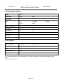
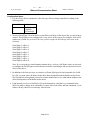
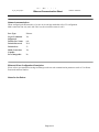
IP Link® De vice Interface
Ethernet Communication Sheet
lutr_13_4070_3.pkn
Revision: 10/6/2010
This document provides additional assistance with wiring your Extron IP Link enabled product to your device.
Different components may require a different wiring scheme than those listed below.
For complete operating instructions, refer to the user’s manual for the specific Extron IP Link enabled product or
the controlled device manufacturer supplied documentation.
Device Specifications:
Device Type:
Manufacturer:
Firmware Version:
Model(s):
Lighting Control
Lutron
Grafik Eye QS - CODE:5.30, BOOT :4.1, HW:2.1
QSE-CI-NWK-E - CODE:7.15, BOOT :2.9, HW:1.0
Sivoia QS - CODE:0.100, BOOT :2.9, HW:8.6
seeTouch QS - CODE:2.50, BOOT :2.3, HW:1.1
Grafik Eye QS, QSE-CI-NWK-E, Sivoia QS, seeT ouch QS
Minimum Software and Firmware Requirements:
IP Link
Compiler
IP Link
Firmware
1.4.0
1.15
G C Version
3.0.4
Version History:
Driver
Version
Date
Notes
3
Extron Certified. T ested on QSE-CI-NWK-E system with a
Grafik Eye, two seeT ouch QS panels, and a Sivoia QS shade.
10/1/2010
Added models Sivoia QS and seeTouch QS. Added Button,
Button Mode, Device select and Shade Position.
2
8/2/2010
1
2/18/2010 Initial version.
Modified the driver to accept serial numbers
Driver Notes:
• Zone Select includes Fade T ime; default Fade T ime is 1 second.
• The Configuration Notes on pg.3 explain how to set up the driver.
Page 1 of 4
IP Link® De vice Interface
Ethernet Communication Sheet
lutr_13_4070_3.pkn
Revision: 10/6/2010
Control Commands & States:
Button
1-100
Button Mode 1
Execute
De vice Sele ct
1-3
Fade
1-59 2
1-10 M in
20 Min
Select
Maste r Le vel (Ste p)1
Up
Down
Pre set Scene
1-16
Off
Se rial Digit 1-8
0-9
A-F
Shade Position
0-100
Zone Select
1-24
Le vel
0-100 in steps of 1
Stop
15 M in
Stop
Status Available:
Connection Status
Connected
Disconnected
Pre set Scene
1-16
Off
Le vel
0-100
Shade Position
0-100
Zone
1-24
1
This command has press/release functionality. The stop command is used for configuration purposes
only.
2
This value is in seconds.
Page 2 of 4
IP Link® De vice Interface
Ethernet Communication Sheet
lutr_13_4070_3.pkn
Revision: 10/6/2010
Configuration Notes:
1. Use the Device Select command to select the type of device being controlled according to the
following table:
Device Select
1
2
3
Device
Grafik Eye QS
QS Shade
seeTouch QS
2. Next use Serial Digit 1-8 in the driver to match the serial digit on the device that you are trying to
control. This will have to be configured for every device in the system. For example, if the serial
number on a Grafik Eye is 00AC123D, then you will configure the Serial Digits in the driver as the
following:
Serial Digit
Serial Digit
Serial Digit
Serial Digit
Serial Digit
Serial Digit
Serial Digit
Serial Digit
1 will be 0
2 will be 0
3 will be A
4 will be C
5 will be 1
6 will be 2
7 will be 3
8 will be D
Note: If you are going to control/monitor another device, such as a QS Shade, then you also need
to configure the Serial Digits to match that device before controlling it and use the correct Device
Select in the driver.
3. In addition to the first two steps, to control a seeTouch QS keypad or the front panel of a Grafik
Eye QS, you must select the button in the driver that corresponds with the buttons on the device.
See Appendix A in integration protocol or contact manufacturer to see what button number in the
driver corresponds to what button on the device.
4. Light intensity levels on a Grafik Eye QS can be changed by using the Level command in the
driver. In order to change level command, you must select zone select and fade commands. Level
Status will only show level of currently selected zone.
Page 3 of 4
IP Link® De vice Interface
Ethernet Communication Sheet
lutr_13_4070_3.pkn
Revision: 10/6/2010
Network communication:
When configuring the Ethernet driver, be sure device settings match that of the GC configuration.
Multi-connection can only work with 2 devices; the second user name is nwk2.
Port Type :
Ethernet
Logon Cre dentials
Supporte d:
Default Use r Name:
Yes
Default Password:
N/A
Default Port:
23
Multi-Connection
Capable :
Port Changeable :
Yes
nwk
No
Ethernet Driver Configuration Description:
Please refer to user manual for settings and changes to the network communication parameters such as: User Name,
Passwords and Port Number.
Notes for the Device:
Page 4 of 4