1
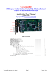
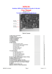
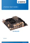
VoverlaX
Realtime Text and Graphics Overlay on Video PCI-Express Card
User Manual
Version 1.0.0.2
Copyright © 2014 Inventa Australia Pty Ltd
Table of Contents
1. Main Features & Functions
2. Package Contents
3. Minimum System Requirement
4. Hardware Installation
5. Software Installation
6. Starting the Software
7. Operate VoverlaX Card
7.1 Generic Operations
7.2 Overlay Items
7.2.1 Text Overlay Item
7.2.2 Timer Overlay Item
7.2.3 Graphics File Overlay Item
7.2.4 Card Operation Overlay Item
7.2.5 Window Overlay Item
7.3 Overlay Item List
7.4 Using Multiple VoverlaX Cards
8. Support
9. Source Code
VoverlaX User Manual
Page 1
-------------------------------------------------------------------------------------------------------------------------------------------------------------------------------------------------------------------------------------------------------------------------------------------------------------------------------------------------------
2
2
2
3
3
4
4
5
6
7
9
10
12
13
14
14
15
15
Version 1.0.0.2
Main Features & Functions:
VoverlaX is a Realtime Text & Graphics on Video Overlay Card with many features & functions:
Realtime overlay superior-quality PC-generated text, graphics and video on incoming video signal
Incoming Video Output and PC-Generated Overlay Display are real-time without visual delays
256 Level Alpha blending control on all colour pixels mixed with input video at 720X576(480) resolution
Instant on-board overlay memory read and write without any delay on outputting video signal
Un-limited PC-generated text, graphics and video can be overlaid simultaneously on incoming video
Output video with overlaid graphics data is always synchronized with input video
Multiple cards up to 32 can be run on the same PC controllable by the same software
Full software control on video brightness, contrast, hue and saturation
PAL and NTSC video format software selectable, input signal type automatically detected
SVideo and Composite Video Input and Output, Input Socket software selectable
SVideo output, main and secondary Composite video output ports
Secondary video output port can be separately configured independent of the main video output
Output ports can be software configured to display video only, video plus overlay, overlay only
Built-in TBC function always provides clear video output even from weak and noisy incoming signal
Automatic Video Pass through on BNC sockets at Power-Off
Colour Adjustment on entire video, separate output ports, and user-definable rectangular area
Overlay Text String support for different font colour, font name, font size and Unicode input
Overlay Graphics Files support for BMP, JPEG, GIF, PND, TIFF and Targa format
Apply single or a range of “Transparency Colours” on Graphics Files to realize “Blue-Screen” effect
Overlay Timer support for time, date, mille-second, frame number
Overlay Card Operation support for instant screen clear, area alpha change, port I/O selection, etc.
Overlay Windows support for constantly displaying any window’s content to external TV & VCR
Constant Alpha Channel Value Change under software control for timing and increment
Horizontal and Vertical Moving Text & Graphics Overlay with software configurable steps and times
Instant Overlay Display to external TV from any combination of overlay items constructed & loaded
Save and Open Overlay Item List Files for repeated use of complicated overlay schemes and patterns
Individual Colour Bar Display on Main and Secondary Output Ports
Full SDK for Software Development inc. full C++, VB, C# source codes of fully functioning executables
Hardware wise, VoverlaX card is an improved version of its PCI counterpart Voverlay:
-Host Interface is 1-Lane PCI-Express instead of PCI
-PCB Dimension is smaller at 101mm(H) x 132mm(L) (Voverlay is 102mm x 160mm)
-Main Output and 2nd Output ports now use the same higher quality encoder IC.
The software also has some improvement as listed at Section 6.5 of the VoverlaX SDK User Manual,
which lead to new capabilities such as Colour Bar display, Automatic Detection of incoming signal type,
direct SDK access to decoder/encoder IC register, on-PCB eeprom read/write, Unicode text overlay,
Colour Change on Rectangle Area, etc.
Multiple PCIe VoverlaX and PCI Voverlay cards can simultaneously install and run in the same PC.
2. Package Contents:
VoverlaX PCIe Card
One Installation CD
One User Manual
One SDK Manual
3. Minimum System Requirement
Hardware: Intel or AMD CPU based PC, one empty 1XPCIe (One Lane PCI-Express) slot.
Software: Microsoft Windows XP, Vista or Windows 7 / 8, 32-Bit or 64-Bit. Please note running the
CSharp.exe or VoverlaXVB.exe application will need the Microsoft .Net Framework 3.5 installed.
VoverlaX User Manual
Page 2
Version 1.0.0.2
4. Hardware Installation
Un-plug the PC’s power cable, open PC case, locate a free PCIe slot (can be of any lane), plug in the
VoverlaX card and screw it firmly to the back-panel.
Plug in video cables between the external video input/output devices and VoverlaX. To view the
incoming video mixed with overlaid text/graphics, external TV monitors need to be connected to the
output sockets of the VoverlaX card. Alternatively, video capture cards like Inventa MPEGIO2 /
USBOSDM2 etc. can be used to accept video and overlay output signals from VoverlaX.
5. Software Installation
Software installation has two steps: device driver software installation and application software
installation.
5.1 After hardware installation and PC reboot, MS Windows will inform that new hardware is found:
5.2 Put the VoverlaX installation CD into PC’s CD/DVD drive, click “Next” button, let Windows
search for device driver specifically from the “drv” folder on the installation CD Disk: search the
drv\x86 if the Windows is 32-Bit, or search the “drv\x64” folder if the Windows is 64-Bit. During
the driver installation, ignore those warnings such as “Windows cannot verify the publisher of this
driver software…” etc, select “Install this software anyway” to keep going, until the driver is
installed, then check the Windows’ “ControlPanel” to make sure the
“System->Hardware->DeviceManager” window’s “Sound, video and game controllers”
category has line “VoverlaX 1.0” listed without question/exclamation mark for each VoverlaX card:
VoverlaX User Manual
Page 3
Version 1.0.0.2
When device driver has been installed properly, Windows will have a pop-up message box at the
lower right corner of the screen:
Please note: after re-installing MS Windows on a PC with VoverlaX card remaining seated in
PCIe slot, one “Other PCI Bridge Device” or similar line will appear in the Windows’
ControlPannel->System->Hardware->DeviceManager window under the “Other devices”
category:
preceded by a yellow exclamation mark circle, since
Windows will not(cannot) install the device driver software. This item will need “update driver”
operation(right-mouse click then select “Update Driver Software…”) to install the proper driver
software from the “drv” folder on the Setup CD, before the VoverlaX card and application
software can be used properly.
5.3 To install the application software, click “Next” on the “Welcome to the VoverlaX Setup Wizard”
window --- which normally starts up automatically after inserting the set-up CD, or will appear after
double-clicking the “Start.bat” software on the set-up CD (there might be a vc++2008
Redistributable installation and a .Net Framework 3.5 installation preceding this Wizard window if
these two software have not been installed already):
,
.
then follow the on-screen instructions to install the application software.
5.4 To remove the installed software, run “Uninstall.exe” from the VoverlaX program group.
6. Starting the Software
After a successful application software installation, a “VoverlaX.EXE” shortcut icon
will appear
on the Windows’ desktop. Mouse double-clicking this icon will start the software. The software can also
be started from Window’s “Start->Program Files->Inventa->VoverlaX” group.
7. Operate VoverlaX Card
Once started, VoverlaX will display its main window:
VoverlaX User Manual
Page 4
Version 1.0.0.2
Mouse-clicking the “Action” menu will show its menu items:
Selecting the “Setup Card Overlay” item will start the “Setup VoverlaX PCIe Overlay” window,
where all the major operations for VoverlaX card can be accomplished:
The Setup Window arranges its functions in several main areas: on the top and at the bottom are the
Generic Operation areas, in the middle on the left is the Overlay Items area, on the right is the Overlay
Item List Box, and in between the Item and Item List Box areas there are Operation Buttons that can
be used for Overlay Items and Item List, such as Display Current Item, Add Item to Item List, Save /
Open Item List File, etc.
7.1 Generic Operations
The top area of the Setup Overlay Window lists several generic operations, inc. overlay card
selection(when there are multiple cards installed), still image grabbing which will display the grabbed
video and/or overlay image in the application’s main window, Signal Colour Setup (through opening
another dialog window as shown below), and input signal testing operation --- note when there is input
signal, pressing Test Input button will show the actual incoming video signal type, which might not be
necessarily the same as set up by the “Card Operation” overlay item ----- if they are not the same then
the output video signal normally is distorted.
VoverlaX User Manual
Page 5
Version 1.0.0.2
The “Signal Colour Setup” Dialog allows different colour changes in the output video frame:
The “All Ports Colour” affects all output ports, the “Main Output” and “2nd Output” Colours affect
main and 2nd output ports separately, while the “RECT Colour” only affects a user-definable rectangular
area on the output ports:
The bottom area on the “Setup VoverlaX PCIe Overlay” Window also has some generic operations
including “Clear All Overlay”, Colour Bar display, I/O Chip Registers Read and Write.
The “MainOutput ColourBar” and “2ndOutput ColourBar” boxes will display colour bars on the
Main Output’s Composite and SVideo ports, and/or the Second Output’s Composite port (the lowest
BNC socket). Note colour bar display will not affect still image grabbing function: grabbed still image is
as if the colour bar is not on.
The Chip Register Write can directly alter on-board video decoder/encoder ICs’ operations.
7.2. Overlay Items
Below the Generic Operation area, on the left is the Overlay Item selection area. Overlay Items have Item
Types such as Text, Timer, Graphics File, Card Operation, and Window --- theses are used to
differentiate the functions and features each type of item can operate. Overlay Item Types are selected
through the “Item Type” Combo box:
. Each time a different Item Type is
selected, specific buttons and combobox etc controls relevant to that Item Type will be displayed.
VoverlaX User Manual
Page 6
Version 1.0.0.2
between the “Overlay Item” and “Overlay Item List” areas will
Pressing the “Display” button
display the currently selected Overlay Item’s contents onto the video output ports immediately: e.g., when
“Clear All” Card Operation Item
is selected, pressing “Display”
button will clear all overlay contents on all the video output ports.
Pressing the “Stop” button
will stop the displaying.
Clicking the “Clear All Overlay” button
current VoverlaX card.
will erase all the displayed overlays on the
7.2.1 Text Overlay Item
Text Overlay Items allow static or moving text to be displayed over incoming video. Many parameters,
inc. alpha blending, colour, font, transparency, location, duration, etc can be selected and changed.
Appropriately combining these parameters, text with numerous different displaying-features can be
output on external TV overlaid over the incoming video, or by themselves without incoming video. For
example, the settings in the previous screenshot will create a blinking text “Blink” blinking every half a
second, while slowly moving across the top of the video screen:
. The following settings
(note “AlphaBk” is set to 126) will create a word “Blink” with half-transparent background colour:
.
As shown in the screenshot, the Text Overlay Item has two time-changing parameter sets:
(1) Alpha Start & Alpha End Change: Setting these parameters to different values and giving some
values to the Alpha Step, Interval parameters will cause the displayed text to have a changing
visibility every “Interval” time in “Step” increment/decrement, such as gradually fading in or
fading out. The “Alpha Rotate” controls when the changing “Alpha Start” value reaches the
“Alpha End”, if it will gradually change back from the “Alpha End” to “Alpha Start” in “Step”
increment/decrement, or it will abruptly jump back to the original “Alpha Start” value. The
VoverlaX User Manual
Page 7
Version 1.0.0.2
Alpha “Duration” (below AlphaBk field) controls how long this Alpha Start<-> Alpha End
visibility change will last: a zero duration means the changes will last forever until being cancelled
specifically, e.g. by pressing the Stop button.
(2) X/Y Location Change: Setting the (X1, Y1) and (X2, Y2) values different will cause the text to
move horizontally or vertically, in the increment of “Move Step” value, every “Interval” time,
for “Duration” period (zero Duration means moving forever until being manually stopped):
The “Oneway Move” and “Return Move” check boxes control if the movement will repeat when
reaching the (X2, Y2) position.
As shown in the following examples, the “AlphaBk” value controls the visibility of the text’s
surrounding background colour when the “BkMode” is Opaque and the Transparent CheckBox is
cleared:
,
.
The text Font Name, Font Point, Foreground Colour, Background Colour, Background Mode,
Transparency can all be changed by using the corresponding buttons.
Note to create Transparent Background text such as
, the “Background Colour” must be set to Black
(RGB = 0,0,0), the BkGr Mode must be “Opaque”, and the “Transparent” checkbox must be cleared.
If the Background Colour is non-black then the resulting text will have a background of Background
Colour such as this (Background Colour is green):
VoverlaX User Manual
Page 8
Version 1.0.0.2
Ticking the “Transparent” box can make 2 partially overlapped text items both appear properly like this:
Ticking the Unicode box
below the Text String field allows typing Unicode characters (Chinese,
Japanese, Korean etc) as text overlaid on incoming video.
7.2.2 Timer Overlay Item
Timer overlay item has similar parameters as Text overlay items, except the displayed text is always the
current time (and date if “Display Date” checkbox is checked). The setting in the screen shot below
displays a one-second interval timer at (20, 0) position with transparent background(Background Colour
must be Black) that will run forever until being stopped manually (since “Duration” is zero):
.
The “Erase Prev. Timer” checkbox controls if to clear the previously displayed timer (if any) when the current
timer item is displayed. Note when a new Timer is defined and the “Display” button is clicked, any previously
defined Timer will be automatically stopped since one VoverlaX card can only display one Timer at any time.
Similar as the “Display Date” checkbox, the “Display MS” controls if the Mille-Second will be displayed,
while the “Display FN” controls if the incoming video’s Frame Number will be displayed.
The Font and Alpha parameters have the same effects for the Timer Items as for the Text Item, but the
Timer Item will not move its X/Y location as the Text Item.
VoverlaX User Manual
Page 9
Version 1.0.0.2
7.2.3 Graphics File Overlay Item
Graphics File Items allow graphics files to be displayed over incoming video or by themselves at the
output video ports. Supported graphics file types are .BMP, .JPG, .GIF, .PNG, .TIF, and .TGA.
Apart from the file name selection, this item has several new parameters:
(1) Transparency Colour
When “Transparent” checkbox is ticked, the overlay process will not display the pixels from the
graphics
file whose colour RGB values and the “Transparency Colour” value have minimum difference, that is:
abs(Rp - Rt) + abs(Gp - Gt) + abs(Bp - Bt) <= TKErrorRange;
where abs(X) is the absolute value of X,
Rp/Gp/Bp is the RGB value of the pixel on the graphics file,
Rt/Gt/Bt is the RGB value of the TransparencyKey Colour,
TKErrorRange is a value >= zero as supplied on the screen.
For example, when “Transparent” checkbox is ticked and the “Transparency Colour” set to “blue”
(RGB= (0,0,255)), a graphics file with people in front of a blue background will be displayed only with
the people over the incoming video, the blue background becomes invisible, achieving in a “blue-screen”
effect.
(2) TKErrorRange
This value makes pixels on the graphics file whose colour values and the “Transparency Colour” value
have minimum difference as indicated above to be invisible(exposing the underneath video content).
Setting this value to be larger than zero will be useful when the area to be made invisible contains nonuniform colour, e.g., a white background contains pixels with colours close to but not exactly the pure
white, as illustrated in the following example where the same overlay graphics file is applied on the same
video but on the left VoverlaX card with TKErrorRange =0, while on the right VoverlaX card with
TKErrorRange =220:
VoverlaX User Manual
Page 10
Version 1.0.0.2
(3) Clear Old Overlay Value
This box is only meaningful when box “Transparent” is also ticked:
If Clear Old Overlay Value is ticked, then those pixels in the graphics file whose colour values and the
“Transparency Colour” have the minimum difference (as described in the “Transparency Colour” above)
will become totally transparent, i.e., the video underneath them will be exposed.
If this box is cleared, then those pixels in the graphics file whose colour values and the “Transparency
Colour” have minimum difference as described in the “Transparency Colour” above will combine (logical or)
their old alpha value with the new alpha value on screen, so that if the resulting alpha is nonzero then some
degree of overlay will appear on top of the video – this is useful for example to display an half-transparent
background exposing some of the video underneath. The following are examples using the same graphics file
with red text ABCD in front of a white background, and Transparency Colour is white, Alpha Start / Alpha
End are 128:
(1)Transparent and Clear Old Overlay Value Ticked
(2) Transparent Ticked, Clear Old Overlay Value Cleared
(4) Raster Operation
This controls how the pixels of the graphics file will be combined with the overlay pixels already being
displayed on the same position by previous Overlay operations(if there is any): SRCCOPY means the
new pixels completely replace the original pixel, SRCAND means the new pixels do logical AND with
the original pixels, the BLACKNESS means display black at the positions, etc.
Alpha change, X/Y change, duration, etc parameters have the same meaning as in Text and Timer items.
Graphics File Item has no “AlphaBk” parameter since it has not background colour.
VoverlaX User Manual
Page 11
Version 1.0.0.2
Each time a non-targa(not .tga) graphics file is loaded, its width and height are automatically loaded into the
. When displaying a graphics file item, using these width
“Width” and “Height” fields:
and height, or making these two fields all zeroes, will put the graphics exactly as their original width and height
(in pixels) onto the external TV. If supplying a width or height different from the graphics file’s original width
and height, the displayed graphics will be shrunk or expanded accordingly. Note the current shrunk mechanism
does not guarantee a perfect shrunk image with proper colour, so when displaying graphics files with
dimension larger than the maximum screen resolution (720 X 576-Pixel for PAL, 720 X 480-Pixel for NTSC),
using an external graphics software such as MS Paint or Adobe PhotoShop to shrink them first is recommended.
Targa graphics files (.tga) will not have their width and height automatically calculated and they can not be
shrunk or expanded.
7.2.4 Card Operation Overlay Item
Card Operation Overlay Item operates the VoverlaX card directly, normally without involving any PCgenerated graphics data, except in the “Overlay Area Set Colour” operation: if the “Transparent” checkbox
is not ticked, the Foreground Colour will be used to fill all the area’s pixels; if the Transparent checkbox is
ticked, then the Foreground Colour will be used to fill the area’s pixels that have colours different from the
Transparency Colour. Also in this “Overlay Area Set Colour “ card operation, if the Transparent is ticked,
and the Move Step and Interval fields have values, the area’s alpha and colour value setting will take place
gradually: if the MoveStep has a positive value, the gradual alpha and colour change will happen from left to
VoverlaX User Manual
Page 12
Version 1.0.0.2
right within the specified area (X1, Y1) (X1+Width, Y1+Height), in “MoveStep” pixels every “Interval”
mille-second, while if the MoveStep is negative, the gradual alpha and colour change will take place from top
towards the bottom within the specified area(X1, Y1) (X1+Width, Y1+Height), in “MoveStep” pixels every
“Interval” mille-second.
The “Restore Default Setup” item will restore all IC register values back to card initial values.
Changes made by Card Operation will be remembered internally by the VoverlaX card even between
PC power-down and power-up.
7.2.5 Window Overlay Item
Window Overlay Item allows any window on the desktop top to be displayed at video output ports, in front of
the incoming video or by itself. This is useful to create a “Video in Video” result on TV, or display a live
animation to external TV, etc.
The window selection is through a window’s handle, or its class name, title, or its root window’s class name
and title. Pressing the “Get A Window Handle” button
once, then move the mouse
cursor(now changed to I-Beam shape) to any window and single click that window, that clicked window’s
handle, class name, title and root window’s class name, title values will be copied into the corresponding fields
.
on the Setup Overlay Window:
Clicking the “Client Area Only” checkbox means only displaying the selected window client area’s contents.
Clicking the “Erase on Exit” checkbox means the window’s display will be cleared when the display duration
expires or the display is manually stopped.
The “Pause Time” means how long the executing thread will pause in between displaying consecutive frames
of the selected window. For a live video/animation displaying window, set this time to 30~80 mille-seconds
will give good smooth moving result on the output video ports.
VoverlaX User Manual
Page 13
Version 1.0.0.2
Click the “Window Content Static” if the content of the window is not changing constantly.
Click the “Transparent” check box and select a colour from the “Transparency Colour” button
initiated colour dialog, if you wish to make some portion of the window transparent (invisible), e.g.
making the blue background to disappear on the live video.
Click the “Clear Old Overlay Value” to make the “Transparency” effect clean without shivering pixels
flying around. This box has the same significance as explained in the “Graphics File Overlay Item” section,
and it is only meaningful when the “Transparent” box is ticked.
7.3 Overlay Item List
The “Overlay Item List” is for holding multiple Overlay Items, so that they can be displayed
simultaneously on external TV, or they can be saved as files for later repeated use. Pressing the “Add”, or
“Delete” button in the middle of the screen will add or delete items into or from the Overlay Item List
box, while with one item selected in the list box, pressing “MoveUp” or “MoveDown” button will
change the selected item’s position in the list.
When some items have been selected in the Item List box, pressing the “Display Selected Items” button
will display these items’ contents on the video output ports, in the order of their positions in the list box:
Pressing the “Stop” button will stop the displaying.
The “Save” and “Open” buttons are used to save the items inside the item list box (if any) to files, and to
load a file’s contents back into the Item List Box (when loading from an item list file, items already in the
list box will be cleared).
7.4 Using Multiple VoverlaX Cards
To operate multiple (2~32) VoverlaX cards on the same PC, select each card’s number from the
“Selected Card:” Combo box (first card is 0), then apply any operation on this card.
When using timer-based overlay items such as Timer or moving text, manual start of an item will
automatically stop other timer-based items previously defined even on another VoverlaX card. For
example, whenever a “Timer” Overlay Item is started on the currently selected card, the previously
VoverlaX User Manual
Page 14
Version 1.0.0.2
applied Timer item on another VoverlaX card will be automatically stopped. To make multiple cards all
displaying their own Timer Overlay Items simultaneously, the Overlay Item List needs to be used:
define a Timer for each individual VoverlaX card then click the “Add” button to add this Timer into the
Overlay Item List ---- when all timers for all cards are added to the Overlay Item List, click the “Select
All” button below the Overlay Item List ListBox, then click “Display Selected Items” button next to it,
all VoverlaX cards with Timer defined will start displaying overlaid timer simultaneously.
8. Support
Technical support is at [email protected].
9. Source Code
The VoverlaX.exe software is supplied with full C++ source code together with the VoverlaX card’s
SDK. A sample VisualBasic application VoverlaXVB.exe and a sample C# application CSharp.exe are
also supplied with full source codes: all these applications with source codes and their Microsoft
VisualStudio project files are under the “src” folder on the Setup CD. Please note Microsoft .Net
Framework 3.5 is required to run the VoverlaXVB.exe and CSharp.exe.
VoverlaX User Manual
Page 15
Version 1.0.0.2