1
Installation and Operating Manual
Solar Controller MPP 165 Duo Dig.
Solar Controller MPP 250 Duo Dig.
Solar Controller MPP 350 Duo Dig.
12 V / 12 A (165 Wp)
12 V / 18 A (250 Wp)
12 V / 25.5 A (350 Wp)
No. 1710
No. 1715
No. 1720
Please read the operating manual of the solar controller thoroughly prior to use connection and start-up.
MPP Solar Controller for high-quality campers, caravans and boats.
VOTRONIC Solar Controllers of series "MPP" (Maximum-Power-Point) with characteristic line of charging „IU1oU2“
are the link between solar panel(s) and battery (batteries).
Controllers according to the MPP technology are continuously and automatically calculating the maximum power yield
(MPP) of the solar modules several times per minute. The voltage surplus of the solar module will be transformed to a
higher charging current for the battery (realised by high-frequency switching controller technology with high efficiency).
This surplus of charging current ensures short charging times and the best possible power yield of the solar system.
Working fully automatically and maintenance-free, the solar controllers MPP offer the following functions:
Increased MPP charging current compared with conventional controllers, due to ultramodern controller technology
(microprocessor) by 10 % to 30 % (efficiency > 95 %). This enhanced capacity shows particularly in cooler times of the
year, such as in case of foggy weather conditions or gloomy diffuse light (winter break).
Switchable characteristic lines of charging for optimum charging of Gel/dryfit/AGM/fleece or acid/lead-acid, as well
as LiFePO4 batteries (see table 1).
The charging voltage being free from peaks is controlled in such a way, that any overcharging of the batteries is
excluded.
Two Battery Charging Ports: Automatic charging of the main battery or board battery (Board I):
Support charging and trickle charging (max. 1 A) of the vehicle's starter battery (Start II) with overcharge protection.
Unattended Charging: Standard protection against overload, overheating, reverse battery and back discharge of the
battery (in case of insufficient solar power, such as at twilight, at night etc.).
Parallel and Floating Operation: Observation of the characteristic lines of charging, even with simultaneous operation
of consumers.
Overcharge protection: Reduction of the charging current of the battery in case of excessive solar power and full
battery. Immediate recharging in case of power consumption to ensure always the best possible charging state of the
battery.
Characteristic Line of Charging "IU1oU2": A defined charging boost (U1) avoids harmful acid accumulation and
provides compensation charge to the individual battery cells. After that, automatic trickle charging (U2).
Charging Cable Compensation: Automatic compensation of voltage losses on the charging cables.
On-board Mains Suppression Filter: Unproblematic parallel operation with wind-driven generators, petrol-driven
generators, mains supply chargers, dynamos etc.
Measurement Output for EBL (Electroblock of the Vehicle): Allows convenient application of the (solar) current
display being installed in the electroblock for supervision of the solar system.
Terminal „AES“ (only MPP 250 Duo Dig. and MPP 350 Duo Dig.):
Automatic commutation of ELECTROLUX / DOMETIC refrigerators with “AES” (Automatic Energy Selector) from gas
operation to 12 V operation in case of excess solar power.
Connection for temperature sensor (order No. 2001):
Automatic adaptation of the charging voltage to the battery temperature. In case of low outside temperatures, full
charging of the weaker battery is improved, and in case of summery temperatures unnecessary battery gassing will
be avoided.
This is highly recommended, if the battery is exposed to strong variations in temperature, such as in the motor
compartment.
Ready for connection of the Votronic Solar Displays for optimum control of the system:
LCD Solar Computer S: The LCD display indicates the following values: Battery voltage, charging current, charging
capacity, stored capacity and energy (V, A, W, Ah, Wh).
--2--
Open acid batteries and batteries being „maintenance-free according to EN / DIN“:
Check the acid level periodically!!
Recharge totally discharged batteries immediately!
Store only fully charged batteries and recharge them periodically!
Safety Regulations and Appropriate Application:
The solar controller has been designed according to the valid safety regulations.
Appropriate application is restricted to:
Charging of lead-gel, lead-AGM, lead-acid or LiFePO4 (with integrated BMS!) batteries of the
indicated nominal voltage and simultaneous supply of the consumers being connected to these
batteries in fixed installed systems.
2. Solar panels up to the maximum power rating (Wp) of the used solar controller.
3. The indicated cable cross sections at the charging ports and at the panel input.
4. With fuses of the indicated capacity near the battery to protect the cabling between battery and
charging ports.
5. Technically faultless condition.
6. Installation in a well-ventilated room, protected from rain, humidity, dust, aggressive battery gas, as
well as in an environment being free from condensation water.
Never use the unit at locations where the risk of gas or dust explosion exists!
Cables are always to be laid in such a way that damage is excluded. Observe to fasten them tightly.
The connection cables have always to be led from below to the solar controller to ensure that
penetrating humidity cannot reach the controller in case of failure, which will result in destruction of the
controller.
Never lay 12 V (24 V) cables and 230 V mains supply cables into the same cable conduit (empty conduit).
Check live cables or leads periodically for insulation faults, points of break or loosened connections.
Occurring defects must be remedied immediately.
The unit is to be disconnected from any connection prior to execution of electrically welding or work on the
electric system.
If the non-commercial end-user is not able to recognize the characteristic values being valid for a unit or the
regulations to be observed, a specialist is always to be consulted.
The user/buyer is obliged to observe any construction and safety regulations.
Except for the fuse, the unit is not equipped with parts, which can be replaced by the user.
Always use replacement car fuses of the indicated capacity!
Keep children away from the solar controller and the batteries.
Observe the safety regulations of the battery manufacturer.
Deaerate the battery room. Protect the unit from aggressive battery gases.
Ensure sufficient ventilation of unit and panel!
Strictly observe the instructions of the manufacturer for installation of the solar panel.
Non-observance may result in injury or material damage.
The warranty period is 24 months from the purchase date (against presentation of the sales slip or invoice).
The guarantee will be void in case of any inappropriate utilisation of the unit, if it is used beyond the
technical specification, in case of improper operation, intrusion of water or external intervention. We do
not assume any liability for any damage resulting hereof. The liability exclusion is extended to any service
being executed by third, which has not been ordered by us in writing. Service is to be effected exclusively
by VOTRONIC Lauterbach.
1.
--3--
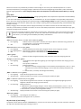
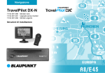
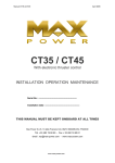
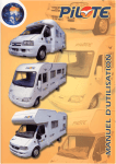
Connection
Plan:
Never connect the "-"
panel connections to
ground/car body/battery ""!
Note:
The connection plan shows the maximum terminal assignment for operation of all existing functions of the solar
controller. The minimum terminal assignment consists of the solar panel inputs ("+" and "-") and the connections of
the main battery.
Always connect the fuses as close as possible to the batteries (cable protection!).
Required Cable Cross Sections, Notes
+/- Panel cables, length as required
+/- Battery I cables, length max. 2 m
Fuse close to battery I
MPP 165 Duo Dig.
2
2.5-4 mm
2
2.5-4 mm
15 A
MPP 250 Duo Dig.
2
4-6 mm
2
4-6 mm
20 A
MPP 350 Duo Dig.
2
6-10 mm
2
6-10 mm
30 A
Cut-off Relay:
The cut-off relay, which exists in most of the vehicles, can, of course, still be used. (For charging by the
dynamo, the cut-off relay connects the board battery to the starter battery during running motor of the
vehicle. The cut-off relay is not included in the connection plan).
--4--
Mounting:
Screw-down the solar controller on an even and hard mounting surface at locations being protected from humidity and
near the main/board battery (BOARD I) to ensure that the length of the battery's connection cable is as short as possible.
Vertical installation of the controller is highly recommendable (the terminals for solar panel and batteries point down).
This mode of installation improves cooling of the unit and avoids that water runs along the connection cables of the solar
panel into the solar controller, even in case of damaged seals.
If used, the cable to the starter battery (START II) can be longer.
Despite the solar controller's high efficiency, heat is produced. Ensure sufficient ventilation in the environment of the unit,
so that the heat can be carried-off.
The unit might heat-up. Consequently, the vent holes of the casing should never be covered to ensure full charging capacity
(minimum distance all around: 10 cm).
Connection (See Connection Plan):
The polarities ( + and - ) of solar panel and batteries are absolutely to be observed!
Observe the cross-sections and length measures of the cables!
1.
2.
Connection of the solar controller to the battery "Board I" should be effected first. Cable
Protection:
Insert the fuses near the batteries into the + cables (protection against cable fire)!
The solar panels should be protected from direct sunlight (by covering or shading) prior to
connection.
1.) Main / Board Battery „BOARD I“ (must be connected):
Connect the battery connections of the controller - (Minus) and + (Plus) to the 12 V main battery, observing the correct
polarity and the cross section of the cables (refer to connection plan).
Never operate the controller without the battery „Board I“ . If the battery is not connected, the unit will not deliver a
defined output voltage.
In case of wrong polarity of battery I, the internal safety fuse will be released.
The replacement fuse should have the same capacity, and it should be of the same type (car fuse)!
Parallel charging of two or several batteries of the same voltage (12 V) is admissible. The batteries are to be „paralleled“,
i. e. the „+“ connections of the batteries have to be coupled and should be connected to the „+“ connection of the solar
controller. The minus (-) connections have to be coupled in the same way.
According to the battery manufacturers, permanent parallel operation is admissible in case of two or several batteries of
the same voltage, type, capacity, as well as of the same age (history) in cross connection.
2.) Solar Panel (must be connected):
Shade the panels to minimize sparking during connection and to avoid damages due to eventual wrong polarity.
Observe the cable cross-sections (refer to connection plan)!
If several small solar panels are used, they are connected in parallel (refer to connection plan). Partial shading of the panels
results in average higher capacity (see connection plan).
3.) Starter Battery „START II“ (Option, can be connected):
Connect the second charging port to the second battery using the red connection cable (wire cross section 1.5 - 2.5 mm²).
This cable may be longer. In case of non-utilization, this terminal is left free.
If used, the output for starter battery II will be working with reduced voltage and charging current rates. Thus, the valuable
solar power will be supplied to board/solar battery I being more suitable.
However, the vehicles starter battery II will be kept in a condition, that starting will always be possible, even in case of
longer downtimes and during winter operation.
Connection of the negative pole „START II“ is not required, if the negative pole „BOARD I“ is connected to the
vehicle body. Depending on the length of the cable, it may also be connected to the common negative
connection of the solar controller or to the negative pole of „BOARD I“.
--5--
4.) Plug-type Connection „ Solar Display “ (Option, can be connected):
6-pole tip jack for connection of the Votronic Solar Displays being ready for connection for optimum control of the solar
system:
LCD Solar Computer S:
The LCD display indicates the following values: Battery voltage, charging current, charging
capacity, stored capacity and energy (V, A, W, Ah, Wh) (Order No.: 1250)
5.) "EBL" Connection for Electroblock with Display Panel DT… / LT... (Option, can be connected):
A cable set for connection of the solar controller to the EBL is required. Order No.: 2007 (It is not included in the standard
delivery scope of the controller).
The solar controller supplies a signal at the terminal "EBL" for display of the solar charging current of board battery I
(battery living area), which is suitable for electroblock EBL… with DT…/LT… Display Panel.
The signal cable being required for that, as well as a connection cable for connection of the solar controller to the EBL are
included in the set of EBL connection cables. Cable Length:1 m, each.
6.) „AES“ (Automatic Energy Selector) only MPP 250 Duo Dig., MPP 350 Duo Dig.
(Option, can be connected):
The delivery scope of DOMETIC / ELECTROLUX includes refrigerators with all-automatic energy selection (230 V AC, 12 V DC
or gas).
Particularly in summer, a lot of excess energy might be produced due to strong solar radiation, full batteries and low energy
consumption, which is left unused. The solar controller recognizes this condition and uses the „AES“ output to give a signal
to the refrigerator, which will commutate from gas operation to 12 V operation to benefit from the excess energy (gas
saving).
Connection:
Lead a single-pole cable (0.5-1.5 mm²) from the solar controller's terminal „AES“ to the refrigerator's terminal „T10“.
Function:
The solar controller recognizes the excess capacity (LED „AES“ is lighting). The refrigerator switches from gas operation to
12 V operation. This mode will be kept for at least half an hour to avoid that the refrigerator will be “swinging” between
12 V operation and gas operation.
Should the solar power be still sufficient, the 12 V operation of the refrigerator will be kept.
Should the solar power be insufficient, „AES“ will be switched off by the solar controller, the refrigerator will be switched to
gas operation, it will keep this mode for at least half an hour, and the solar power will be used for recharge of the (possibly
slightly discharged) battery. This mode of operation can only be taken into account in case of sufficient efficiency of the
solar panel and under favourable conditions, such as 110 Wp, better 150 Wp or more.
Option:
Optionally, small 12 V consumers can be operated at the AES output, such as 12 V fans, car relays or refrigerators with
control input D+ (Thetford etc.). It must be observed, that the output must be active for at least half an hour.
The output current of the terminal "AES" is max. 200 mA. In case of larger consumers, the output is limited and
can again be loaded after a cooling down phase.
7.) Temperature Sensor, Input „TS - TS“ (Option, can be connected):
Connection for the external Votronic Temperature Sensor, order No. 2001 (is not included in the standard delivery scope).
For automatic adaptation and correction of the charging voltage to the battery temperature (temperature compensation).
Mounting:
The thermal contact of sensor and battery "Board I" (inside temperature) should be well. Thus, it should be screwed down
to the negative pole or positive pole of the battery. It is also possible to fasten it at the sidewall centre of the battery casing.
Ensure that the installation place is not influenced by any source of heat (motor block, exhaust, heater etc.).
Connection:
Connect the temperature sensor to the terminal by means of a 2-pole cable (cable cross section 0.5 - 1.5 mm²). The polarity
and cable length is of no importance. The solar controller recognizes the sensor automatically.
Effect:
The temperature-dependent charging voltage of battery I will be adapted automatically to the battery temperature.
The temperature sensor measures the battery temperature. In case of low temperatures (winter operation), the charging
voltage will be increased in order to improve and accelerate full charging of the weak battery.
--6-Sensitive consumers are protected by a limitation of the voltage in case of very low outside temperatures. In case of
summery temperatures, the charging voltage is reduced to minimize the load (gassing) of the battery and to extend the
lifetime of gas-tight batteries. (See "Charging Voltage Rates and Temperature Compensation of Board Battery I" on page
10.)
Safety Mode:
Battery Protection: (also see characteristic lines: "Charging Voltage Rates and Temperature Compensation of Board Battery
I):
In case of too low battery temperatures ( -30 °C for lead batteries or -20 °C for LiFePO4) or too high battery temperatures
(from +50 °C), the charging voltage will be reduced strongly to safety charging voltage for battery protection (depending on
the type from 12.75 V to 13.00 V). Safety mode, LED "charge" is flashing, but any charging data being recorded hitherto will
be kept in memory.
Battery charging is then interrupted, but the supply of eventually connected consumers will be continued by the solar
controller, and the battery is allowed to cool down. As soon as the battery temperature reaches the admissible range again,
automatic charging will be continued.
The solar controller recognizes automatically a missing sensor, cable break or short-circuit of the sensor lines, as
well as unreasonable measuring values. In that case, it will switch automatically to the usual charging voltage
rates of 20 °C / 25 °C being recommended by the battery manufacturers.
Pilot Lamps:
"AES" (excess power display, only MPP 250 and MPP 350, green):
If it is lighting:
Sufficient excess solar power is available, the output "AES" for automatic energy selection of
the refrigerator or of a relay control is activated.
Off:
Output "AES" is switched-off.
“Batt. Full“ (Battery fully charged, green):
If it is lighting:
Battery (batteries) has (have) been charged to 100 %, trickle charge U2, finished.
If it is lighting dimly: Main charging process is still effected in the charging phase U1.
Off:
Main charging process is still effected in the charging phase I.
„>80 %“ (green):
If it is lighting:
Battery has been charged almost fully. Solar controller is still in the charging phase U1.
"Charge" (only MPP 165, green):
If it is lighting:
The brightness from slight dimly lighting up to full brightness indicates the charging current
intensity.
Off:
Solar power is insufficient.
If it is flashing:
Battery Protection:
1. Switchover to safety charging voltage in case of battery overtemperature, such as > +50°C,
automatic return and continued charging in case of drop of the battery temperature by
2°C.
2. Disconnection, caused by overvoltage at the battery.
„MPP“ at MPP 165 (control, green):
If it is lighting: Proper functioning of the solar controller.
Short flashing: Display of readiness for service in case of missing solar power (at night).
„MPP“ at MPP 250 and MPP 350 (control, green):
If it is lighting: Proper functioning of the solar controller. The brightness from slight dimly lighting up to full
brightness indicates the charging current intensity.
If it is flashing: Battery Protection:
1. Switchover to safety charging voltage in case of battery overtemperature, such as > +50 °C,
automatic return and continued charging in case of drop of the battery temperature by 2 °C.
2. Disconnection, caused by overvoltage at the battery.
Short flashing: Display of readiness for service in case of missing solar power (at night).
“Batt. Low“ (yellow):
If it is lighting: Low voltage at main battery I.
The battery should be recharged as soon as possible!
All pilot lamps (5) are flashing:
The positions of the selector switches "BOARD Battery" are incorrect. For reasons of safety, the solar controller is switchedoff. Adjust the desired battery type according to table 1.
--7--
Operating Instructions:
Lifetime of the battery:
Recharge totally discharged batteries immediately!
Sulphation of the lead battery plates due to total discharge is to be prevented by soon charging, particularly in case
of high ambient temperatures. If the grade of sulphation is not too intensive, the battery can recover part of the
battery capacity after several charging/discharging cycles.
Partially Discharged Batteries:
In contrast to other battery types, batteries on lead basis do not have any harmful memory effect. Consequently: In
case of doubt, partially discharged batteries have to be charged fully as soon as possible.
Always store only fully charged lead batteries. Recharge them periodically, particularly in case of used (older)
batteries and higher temperatures.
Keep batteries cool and dry; choose an appropriate location for installation.
In case of insufficient solar power and/or high current consumption, the battery should be subject to occasional
full charging by means of a mains supply charger.
Overvoltage Protection:
The 12 V solar controllers protect themselves against connection of excessive battery voltage rates or will be switchedoff in case of defective additional charging systems (chargers, generators or similar systems), switching threshold 15.016.0 V.
Overvoltage Limitation:
Sensitive consumers are protected by means of a limitation of the charging voltage to max. 15.0 V during all modes of
charging.
Overload / Overheating Protection Solar Controller:
The solar controller is equipped with a double electronic protection against overload and with an automatic protection
against adverse installation conditions (e. g. insufficient ventilation, excessive ambient temperatures) by gradual
reduction of the charging capacity.
Voltage Measurement: Measurement of the voltage is to be effected at the battery and never at the solar controller
(loss at the charging cable).
In case of unattended operation, the battery might be totally discharged due to too many consumers and lack
of solar power. We recommend an (undervoltage) protection of the battery by means of the following
appliances:
Votronic Battery Protector 40
(Power rating 12 V / 40 A)
Order No. 3075 or
Votronic Battery Protector 100
(Power rating 12 V / 100 A)
Order No. 3078
--8--
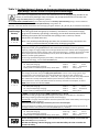
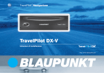
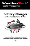
Table 1: For Main Battery I: How to set the correct charging program for the battery
type (design, lead or lithium-iron phosphate technology)
Prior to start-up, imperatively set the correct characteristic line of charging being suitable for the
battery to avoid battery damages! Only use lithium iron-phosphate batteries in execution with
integrated BMS (battery management system)!
Set the slide switch ("BOARD Battery") to the desired position for battery I (board battery) using a small screwdriver.
Either select Lead Battery or Lithium Iron-Phosphate Battery using switch "1".
After that, select the desired characteristic line of charging using the switches „2“, „3“ and „4“, as indicated in the tables:
Switch 1 "below" Charging programs for lead batteries:
Lead Storage
Battery
4
3
2
1
1 2 3 4
If not being specified divergently by the battery manufacturer, the suitable charging
program for the battery type (design, technology) can be determined by means of the
following description and the technical data (voltage rates U1 and U2, nominal
temperature and dwell times U1).
Note: The possible parallel/floating operation with consumers being connected to the
battery is also automatically considered by all charging programs.
„Gel“: Charging program for gel/dryfit batteries:
1 2 3 4
Adapted to closed, gas-tight Gel batteries with determined electrolytes, which are generally
requiring a higher charging voltage level and longer dwell times U1 to achieve short charging times
with particularly high capacity storage and to avoid total discharge, e. g. EXIDE, Sonnenschein dryfitStart, Dryfit-Sport-Line, DETA Gel Battery Funline, Bosch AS Gel Batteries Va/Z, AS Gel Drive
Batteries, AS Gel Lighting Batteries.
If not being specified divergently by the battery manufacturer, also recommended for batteries in
round cell technology, such as EXIDE MAXXIMA (DC).
EXIDE, DETA, VARTA Characteristic Line Gel IU1oU2:
U1 Main/Full Charging:
U2 Full/Trickle/Storage Charging:
Safety mode at insufficient/excess temp. of the batt.:
14.30 V
13.80 V
12.75 V
+20 °C
3-10 h
+20 °C
Continuous
-30 °C/+50 °C
„Lead Acid/AGM1“: Charging program for acid/lead-acid batteries as well as AGM 14.4 V:
1 2 3 4
For charging and trickle charge of supply (board) batteries. Ensures short charging times, high
charging factor and acid mixing for open standard batteries and closed, low-maintenance,
maintenance-free "non-solid electrolyte", "lead-acid", drive, lighting, solar and heavy duty batteries.
Also suitable for recently developed batteries (low-antimonous, batteries with silver-alloy,
calcium/calcium or similar) and batteries with low and very low water consumption, as well as
AGM batteries with the indication 14.4 V.
Characteristic line of charging IU1oU2 Acid/AGM:
U1 Main/Full Charging:
14.40 V
+20 °C
1.5-6 h
U2 Full/Trickle/Storage Charging:
13.45 V
+20 °C
Continuous
Safety mode at insufficient/excess temp. of the batt.:
12.80 V
-30 °C/+50 °C
„AGM2“: Charging Program for AGM / Fleece Batteries 14.7 V:
Adapted to closed, gas-tight AGM (absorbed glass mat) batteries and batteries in lead-fleece
technology requiring a particularly high level U1 for full charging.
ATTENTION: It is highly recommended to check the specification sheet of the battery concerning the
high charging voltage U1 14.7 V.
Unsuitable batteries might age prematurely due to loss of electrolyte!
1 2 3 4
1 2 3 4
Some manufacturers of AGM / fleece batteries are also prescribing a 14.4 V charging program for
charging! In these cases, please set "Lead Acid/AGM1 (14.4 V / 13.45 V).
Characteristic Line AGM/Fleece IU1oU2:
U1 Main/Full Charging:
14.70 V (!)
+20 °C
1.5-5 h
U2 Full/Trickle/Storage Charging:
13.50 V
+20 °C
Continuous
Safety mode at insufficient/excess temp. of the batt.:
12.75 V
-30 °C/+50 °C
These switch positions and other switch positions (such as for LiFePO) are not valid and
are not used (service positions)!
All LEDs are flashing, and the charging port is switched-off by the solar controller for
reasons of safety.
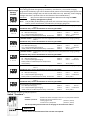
--9-Switch 1 "above" Charging programs for LiFePO4 batteries:
Lead Storage
Battery
LiFePO4
4
3
2
1
1 2 3 4
1 2 3 4
1 2 3 4
If not being specified divergently by the battery manufacturer, the suitable charging
program for the battery type can be determined by means of the following description and
the technical data (voltage rates U1 and U2 and dwell times U1). Generally, lower charging
voltage rates have a positive effect on the lifetime of the LiFePO4 battery.
Attention:
Only connect lithium iron-phosphate batteries with integrated BMS
(battery management system)!
Note: The possible parallel/floating operation with consumers being connected to the
battery is also automatically considered by all charging programs.
„LiFePO4 14.2 V“: Characteristic line of charging lithium iron-phosphate with charging voltage
14.2 V.
ATTENTION: Only connect LiFePO4 batteries with integrated BMS!
Characteristic line LiFePO4 IU1oU2:
U1 Main/Full Charging:
14.20 V
+20 °C
0.5-3 h
U2 Full/Trickle/Storage Charging:
13.50 V
+20 °C
Continuous
Safety mode at insufficient/excess temp. of the batt.:
13.00 V
-20 °C/+50 °C
„LiFePO4 14.4 V“: Characteristic line of charging lithium iron-phosphate with charging voltage
14.4 V.
ATTENTION: Only connect LiFePO4 batteries with integrated BMS!
Characteristic line LiFePO4 IU1oU2:
U1 Main/Full Charging:
14.40 V
+20 °C
0.5-3 h
U2 Full/Trickle/Storage Charging:
13.55 V
+20 °C
Continuous
Safety mode at insufficient/excess temp. of the batt.:
13.00 V
-20 °C/+50 °C
„LiFePO4 14.6 V“: Characteristic line of charging lithium iron-phosphate with charging voltage
1 2 3 4
1 2 3 4
14.6 V.
ATTENTION: Only connect LiFePO4 batteries with integrated BMS!
Characteristic line LiFePO4 IU1oU2:
U1 Main/Full Charging:
14.60 V
+20 °C
0.5-3 h
U2 Full/Trickle/Storage Charging:
13.60 V
+20 °C
Continuous
Safety mode at insufficient/excess temperature
of the battery:
13.00 V
-20 °C/+50 °C
„LiFePO4 14.7 V“: Characteristic line of charging lithium iron-phosphate with charging voltage
14.7 V.
ATTENTION: Only connect LiFePO4 batteries with integrated BMS!
Characteristic line LiFePO4 IU1oU2:
U1 Main/Full Charging:
14.70 V
+20 °C
0.5-3 h
U2 Full/Trickle/Storage Charging:
13.70 V
+20 °C
Continuous
Safety mode at insufficient/excess temp. of the batt.:
13.00 V
-20 °C/+50 °C
„LiFePO4 14.8 V“: Characteristic line of charging lithium iron-phosphate with charging voltage
1 2 3 4
14.8 V.
ATTENTION: Only connect LiFePO4 batteries with integrated BMS!
Characteristic line LiFePO4 IU1oU2:
U1 Main/Full Charging:
14.80 V
U2 Full/Trickle/Storage Charging:
13.70 V
Safety mode at insufficient/excess temp. of the batt.:
13.00 V
+20 °C
0.5-3 h
+20 °C
Continuous
-20 °C/+50 °C
Now, the solar controller is ready for operation.
Switch "Functions":
Switch 1:
Switches 2, 3 and 4:
Selection of either lead (Pb) or lithium iron-phosphate batteries
Selection of the characteristic lines
of charging for lead
(switch 1, below)
or lithium iron-phosphate
(switch 1, above)
The corresponding characteristic lines of charging can be drawn from table 1!
White Lever
Further actions or maintenance of the unit are not required.
--10--
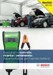
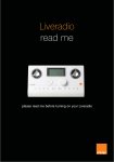
Charging Voltage Rates and Temperature Compensation of Board Battery I:
Lead Batteries:
Charging Program "Lead Acid/AGM1", Characteristic Line IU1oU2
Charging Program "AGM2", Characteristic Line IU1oU2
Charging Program „Gel“, Characteristic Line IU1oU2
TS = If a temperature sensor is used
being connected to the terminals "TS TS"
LiFePO4 Batteries:
Characteristic line LiFePO4 IU1oU2.
The corresponding voltage rates U1 and U2 of the characteristic
lines LiFePO4 can be drawn from table 1!
(Representation: Characteristic Line LiFePO4 14.6 V)
Functions (at the Main / Board Battery „Board I“):
If solar power is missing (at night), the readiness for service of the controller will be indicated by short flashing of the LED
(light-emitting diode) "MPP".
In any operating state, a totally discharged battery is indicated by means of the LED "Batt. Low" (low voltage). Now the
battery has to be recharged as soon as possible (preferably disconnect the consumers)!
MPP 250 Duo Dig. and MPP 350 Duo Dig.: The LED "AES" will be lighting in case of excess solar power, output "AES" is
active.
A lighting LED “MPP” indicates proper control functions of the solar controller. The most favourable working point for the
coordination of solar panel, cabling and battery is always ensured.
--11-1.
Maximum charging current (Phase I) in the lower and mean voltage range of the battery up to the beginning of the
phase U1. The MPP control adjusts to the maximum working point of the solar panel, and - in contrast to
conventional controllers - thus achieves the highest possible battery charging current for short charging times under
the given circumstances (sunlight, module orientation, module temperature and module soiling).
2.
During the following phase U1 the battery voltage will be kept constant on a high level close to the gassing limit, the
battery determines the charging current according to its charging state, the high battery capacity will be charged,
the LED ">80 %" is lighting and "Batt. Full" is lighting dimly.
The MPP control ensures lower panel load and panel temperature, thus allowing an increased efficiency if
consumers are additionally switched-on.
The solar controller controls the charging time, as well as the charging voltage, and switches automatically to the
following phase U2=trickle charge. If the battery has already been charged fully, the charging time will be reduced
accordingly.
3.
During the phase U2 (Full charging/trickle charge) the battery will be kept on its charging level. Only the
compensating recharging current is flowing being required for conservation of the full charge, which is determined
by the battery. The duration of that phase is not limited, the LED „Batt. Full" is lighting intensively, LED ">80 %"
extinguishes.
In contrast to conventional controllers, especially here, the MPP control ensures low panel loads and panel
temperatures. Additional consumers can be held better.
Now, almost the entire solar current is available to the consumers.
Switching back to the phase I or U1 is effected, if the battery had been subject to load for an extended period, or if the solar
controller switches to stand-by mode after sunset.
If a temperature sensor is used for the battery, the voltage values will be slightly higher in case of low outside
temperatures, while they will be slightly lower in case of high outside temperatures.
The output for the „Battery II“ (START) will be working with reduced voltage and charging current rates. Thus, the valuable
solar power will be supplied to board/solar battery „I“ being more suitable. However, the starter battery „II“ will be kept in
a condition, that starting will always be possible, even in case of longer stop periods (e. g. in winter).
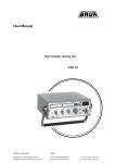
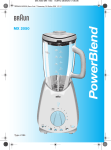
Charging Process (Characteristic Line of Charging IU1oU2) at the Board Battery "Board 1"
In Case of Sufficient Solar Power:
1.
2.
3.
4.
Preliminary charging of totally discharged battery, gentle initial charging
current (I-Phase)
Main charging constant, maximum charging current (I-Phase)
Main/full charging constant charging voltage 1 (U1-Phase)
Full/Trickle charge constant continuous charging voltage 2 (Phase U2)
--12--
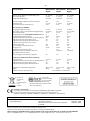
Technical Data:
MPP 165 Duo MPP 250 Duo MPP 350 Duo
Digital
Digital
Digital
Capacity of Solar Module (recommended / max.):
Current Solar Module:
Voltage Solar Module (Voc):
50 - 165 Wp
0 - 10 A
max. 50 V
50 - 250 Wp
0 - 15.0 A
max. 50 V
50 - 350 Wp
0 - 21.0 A
max. 50 V
Nominal Voltages of Batteries Board I and Start II:
Charging Current:
Current Consumption Stand-by (max.):
12 V
0 - 12 A
4 mA
12 V
0 - 18.0 A
4 mA
12 V
0 - 25.5 A
4 mA
Main Port Battery I (BOARD I):
Charging/Floating/Load Current:
Max. Prelim. Charg. Current (totally discharged battery):
Reset Voltage (30 sec):
0 - 12 A
6 A (<8 V)
12.7 V
0 - 18.0 A
9 A (<8 V)
12.7 V
0 - 25.5 A
12,7 A (<8 V)
12.7 V
Charging Programs for Gel/AGM/Acid/LiFePO4 Batteries:
Charging Voltage Limitation (max.):
Integrated Overload Protection (Current Limiting Device):
Integrated Protection against Short-circuit:
Integrated Protection against Overtemperature:
Integrated Cooling Fan with Temp. Control:
Unit Fuse (Type FKS):
Input for Battery I Temperature Sensor:
Charging Timer:
8
15.0 V
Yes
Yes
Yes
-15 A
Yes
3-fold
8
15.0 V
Yes
Yes
Yes
Yes
20 A
Yes
4-fold
8
15.0 V
Yes
Yes
Yes
Yes
30 A
Yes
4-fold
Refrigerator Control Output "AES":
Switching Current Control Output "AES" max.:
---
Yes
12 V/0.2 A
Yes
12 V/0.2 A
Signal Output "EBL" for Display
„Solar“Charging Current Battery Living Area:
Yes
Yes
Yes
Auxiliary Port Vehicle Starter Battery II (Start II):
Charging Current:
Integrated Overload Protection (Current Limiting Device):
Integrated Protection against Short-circuit:
Integrated Protection against Overtemperature:
0 - 1.0 A
Yes
Yes
Yes
0 - 1.0 A
Yes
Yes
Yes
0 - 1.0 A
Yes
Yes
Yes
Dimensions, incl. Mounting Flanges (mm):
Weight:
Ambient Conditions, Humidity of Air:
131 x 77 x 40
131 x 77 x 40
131 x 77 x 40
190 g
210 g
250 g
max. 95 % RH, no condensation
Disposal of
the product
in the
household waste
is not
allowed.
The product
conforms to RoHS.
Thus, it complies
with the directives for Reduction of
Hazardous Substances in Electrical and
Electronic Equipment.
Declaration of Conformity:
According to the stipulations of the regulations 2006/95/EG, 2004/108/EG, 95/54/EG
this product corresponds to the following standards or standardized documents:
EN55014; EN55022 B; DIN14685; DIN40839-1; EN61000-4-2; EN61000-4-3; EN 61000-4-4.
Delivery Scope:
MPP Solar Controller
Operating Manual
Available Accessories:
Temperature Sensor
LCD Solar Computer S
Cable set for connection of the solar controller
to the EBL
Order No. 2001
Order No. 1250
Order No. 2007
Subject to misprints, errors and technical modification without notice.
All rights reserved, particularly the right of reproduction. Copyright VOTRONIC 02/14.
Made in Germany by VOTRONIC Electronic-Systeme GmbH & Co. KG, Johann-Friedrich-Diehm-Str. 10, 36341 Lauterbach/GERMANY
Phone: +49 (0)6641/91173-0 Fax: +49 (0)6641/91173-20 E-Mail: [email protected] Internet: www.votronic.de