1
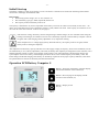
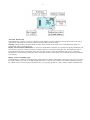
Installation and Operating Manual LCD Battery Computer 100 S with Measuring Shunt 100 A LCD Battery Computer 200 S with Measuring Shunt 200 A LCD Battery Computer 400 S with Measuring Shunt 400 A No. 1262 No. 1265 No. 1268 Precise and complete battery control for all commercial types of lead storage batteries in vehicles and boats. The VOTRONIC LCD Battery Computer S calculates the exact charging state of the battery and displays the charging state like a “fuel gauge for the battery”. In contrast to simple ampere-hour meters, the residual capacity will be determined in ampere-hours (Ah) or the residual charge in % by means of programmed characteristic diagrams of batteries and will be displayed as charging state. Furthermore, the unit is equipped with a programmable terminal for connection or disconnection of consumers or further energy supply units, depending on the charging state of the battery. Apart from this, the LCD Battery Computer S provides the display of the battery voltage (V) of a second battery (starter battery). Due to its various display functions, it allows a centralized supervision of the consumers as well as of the most important processes at the battery at any time. So, it allows quick reactions to undesirable developments or to take corrective measures in good time. The precision measuring shunt for detection of the battery current being provided with the unit is extraordinary robust, very exactly and shows extreme overload capacity (also refer to "Technical Data"). The dimensions of the unit are perfectly adapted to the VOTRONIC modular system. The VOTRONIC modular system includes the tank display units (fresh and sewage water as well as feces), the LCD series (solar display, voltmeter, ammeter and thermometer), as well as the switch and fuse panels. Please read the mounting instructions and operating manual including the safety regulations completely prior to starting connection and start-up. Installation and Connection: Display Unit The small mounting depth (approx. 27 mm) of the electronic system allows flush mounting into furniture boards to ensure, that an optimum installation place can always be chosen. The clear opening of the cutout is min. 71 x 66 mm to ensure safe alignment of the front panel. Please use the delivered drilling jig, which has been designed to consider combination with further display panels. If possible, the rear cutout opening should be covered with electrically nonconducting material to ensure efficient protection of the electronic system and full utilization of the storage space, which might be located behind. The delivered control cable of 5 m length is used to connect the display unit to the delivered current measuring shunt. The connection is executed ready to be plugged in, and the cable should be laid according to the safety instructions. The length of the control cable is 5 m. If this length is not sufficient for connection of the connection unit, the cable extension of 5 m length, order No. 2005, being available as accessory can be used. The total cable length is then 10 m. Measuring Shunt Any battery current should flow over the measuring shunt. Therefore, it is to be installed directly near the battery (batteries). Observe that all consumers and charging devices for the battery must be led over the shunt in order to allow a registration of any battery activity. Battery systems are to be connected according to the plan. -2- Battery Systems: Except of the measuring shunt, no further connection should exist at the negative pole (-) of the battery or at the negative pole of the entire battery system! This concerns consumers, vehicle ground, as well as chargers. Further connections have to be made either to the car body (ground) or, in case of insulated vehicle bodies, to the minus distribution. See connection plan. Ground straps at the connecting screws M8 of the measuring shunt are to be screwed in such a way, that one connection is connected to the negative pole of the battery and the other one with the car body. The arrows on the base of the measuring shunt should point to the direction of the battery (see connection plan). The connections at the measuring shunt should always be tightened firmly to avoid any transition resistance. Permanent high load of 200 A or 400 A might result in heating of the measuring shunt. Ventilate the battery room (gases). Terminals Connection +B1 (Board Battery) For the voltage measurement of the board battery a direct connection from this terminal to the positive pole of the board battery must be made. The cable is to be protected by means of a 3 A fuse directly at the battery. The connection crosssection should be 0.75 mm², at least. This connection also provides current to the LCD Battery Computer S and to the terminal. Connection +B2 (Starter Battery) For the voltage measurement of the starter battery a direct connection from this terminal to the positive pole of the starter battery must be made. The connection cable is to be protected by means of a 3 A fuse directly at the battery. The connection cross-section should be 0.75 mm², at least. Connection Out (Terminal) A freely programmable terminal is at disposal. Depending on the setting, this terminal can be used as timer or for capacity disconnection. In active condition (ON), the battery voltage (+12 V or +24 V) is here at disposal, and it is protected against overload by means of a self-resetting fuse 0.5 A. The terminal can be reinforced by an interposed changeover relay. -3- Connection Plan Except of the measuring shunt, no further connection should exist at the negative pole (-) of the battery or at the negative pole of the entire battery system! This concerns consumers, vehicle ground, as well as chargers. Further connections have to be made either to the car body (ground) or, in case of insulated vehicle bodies, to the minus distribution. See connection plan. -4- Initial Start-up The battery computer is ready for operation, as soon as all electric connections are made at the measuring shunt and the connection to the display unit had been made. Basic Setting: The existing system voltage (12 V or 24 V) must be set. The used battery type (gel, AGM, liquid acid) must be set. The capacity of the board battery must be set. The capacity is indicated in Ah, and it is imprinted on the battery. If several Ah-values can be found, use the value ....Ah (20 h). If several batteries have been combined to a battery system, add the Ah values. Total capacity for 2 batteries at 110 Ah is 220 Ah. This value -220 Ah - must be set (see page 7). After the basic setting, the battery must be charged using a suitable charger (in case of mobile homes using the existing board charger) for a duration of 24 h. This is absolutely required, so that the battery computer is able to recognize 100 % full charging (factory adjustment 75 %) required for starting. If the computer loses its voltage supply (battery disconnected etc.), the capacity must be set again, and the battery must be recharged completely. After adjustment of the battery capacity and after loss of the supply voltage, the capacity, which can be withdrawn, will be set automatically to 75 % (factory adjustment). After that, the battery must implicitly be charged for at least 24 hours with a suitable automatic charger to ensure correct display of the capacity. Only when the battery had been fully charged, the system adjusts itself to "its" battery, and the display will show 100 % or the residual capacity of the battery in Ah. The initial settings and the full charging of the battery are absolutely required to ensure proper capacity indication, and it must be repeated whenever the unit or the battery had been disconnected! Operation LCD Battery Computer S Button 1: Next page of the battery computer display, manual disconnection of the terminal (3s). Button 2: Previous page of the display, manual activation of the terminal (3s). Button 3: Display on/off. Set (3s) -5- Activation, Deactivation The LCD Battery Computer S requires continuous current supply to ensure continuous capacity measurement. The unit is optimized for extremely current saving operation and offers three operation modes. Stand-by: During stand-by mode the display is empty. If the terminal is activated, “ON” will be displayed, and if it is switched-off, “OFF” will be displayed. Display with and without illumination: As soon as the LCD Battery Computer S is operated, the display illumination will be switched-on and will remain activated for 3 minutes. If there is no operation during this time, the illumination will be switched-off automatically. The display shows the same data as before, when the illumination was active. The display illumination is reactivated by pressing any button. The proper function of the button will be effected by pressing the button a second time. Display Contrast / Reading Angle The LCD Battery Computer S is equipped with a high-contrast LC display. Depending on the angle of view, the contrast of the display might be too weak or too high (hidden characters are visible). The contrast can be quickly adapted by pressing the buttons 1 and 3 (increase contrast) simultaneously, or by pressing the buttons 2 and 3 (reduce contrast) simultaneously. -6Displays Battery Computers Use the buttons 1 and 2 to display the next or previous page of the measuring and display values. Voltage: Display of the voltage of the board battery (B1) and of a second battery (B2), such as the starter battery, is possible. The marking triangles at the lower edge of the display point to the displayed battery. Current: The current display informs of the instantaneous load or battery charge. The display shows the instantaneously measured value flowing into or out of the battery. If the current flows into the battery, the display will show a positive current value and the charging symbol “CHARGE”. If the current flows out of the battery, it is negative and the value will be shown with a negative sign. Capacity Display: The microcomputer-controlled measurement accurately counts each ampere-hour (Ah) of capacity during charging and discharging, even in splits. The automatic evaluation of the battery load is effected by means of the programmed characteristic lines of the battery. So, a current rate of e. g. 100 Amperes represents an inferior load for a 600 Ah battery, while this is an extremely high load for a 70 Ah battery. Correspondingly, the large storage battery provides almost its full capacity, but the small 70 Ah battery only 42 Ah or 60 % of the indicated nominal capacity, at best. The result is a correct indication of the available capacity in the battery (residual capacity, charging state), such as it is known from a “fuel gauge”. It is a matter of course, that also the self-discharge of the battery in case of long downtimes will be considered. During charging of the battery, the full charging state will be recognized automatically, and it will be corrected, if required. Depending on the quality of the used charger, the charged capacity may be between 80 % and 100 %. The capacity of the board battery will be displayed in ampere-hours (Ah) and as percentage (%) of the nominal capacity. The bar graph at the left margin of the display represents the capacity in steps of 10 %. Settings Battery Computer: The menu for settings is called by pressing and holding button 3 for more than 3 seconds. The buttons 1 and 2 are used to set the values. In the menu, the button 3 is used to save the setting and to jump to the next menu item. Adjustment of the System Voltage: Adjust the system voltage (12 V or 24 V) of the board mains supply. Adjustment of the Battery Type: Adjust the battery type 1...4 of the board battery. 1 = Lead Acid (Liquid-acid Lead Battery) 2 = Gel 3 = AGM 4 = LiPoFe The battery type is shown in the left lower margin of the display. Adjustment of the Nominal Capacity: The nominal capacity of the battery (see start-up) can be adjusted in three steps. First, the capacity in steps of 100 is adjusted, after that in steps of 10, and after that in steps of 1 Ah. After adjustment of the nominal capacity, the battery computer sets automatically a residual capacity of 75 %. A full charging cycle is required (see start-up). -7- Adjustment of the Terminal Switching-on Threshold: Here, the switching threshold for the automatic activation of the terminal can be adjusted. The switching threshold can be set to 101 %. Thus, an automatic activation will never be reached. Adjustment of the Terminal Switching-off Threshold: The same is true as for the switching-on threshold. An automatic disconnection can be prevented by setting this value to 0 %. The memory for the lowest and highest voltage and capacity can be reset. For this, the button 1 and 2 must be pressed simultaneously for 3 seconds at the respective display. The value is deleted and the display shows “--.-“. A counter shows the time in hours that have passed from the last 100%-charging. Adjustment of the Background Illumination: The background illumination can be adapted from bright to completely dark in steps of 10 % according to the requirements. -8- General Information: Once a year: Check the connecting screws at the measuring shunt for tightness. Check the connection cable for correct contact and damage. Aged batteries: Lead batteries are subject to wear, which will be growing with the age of the battery, the number of charging/discharging cycles, the rate of discharge (frequent total discharge) and other factors, such as extreme temperatures, vibration etc. This results in a reduction of the available capacity. The LCD Battery Computer S is able to consider this loss of capacity in calculation within certain limits. However, we recommend to correcting the set nominal capacity by e. g. 5 % (depending on the battery type and the operating conditions 2 - 10 % lower), once a year. . Cleaning: We recommend to use a damp microfibre cloth with pure water or, if required, with water with a few soap. Take care, that no liquid flows along the display screen or the edges of the front panel! Never use solvents, aggressive household cleaners, and scratching or abrasive agents or objects to clean the front panel and particularly the display itself. Failure Corrective Action: No display at all: a) Reverse battery: Check! b) Battery is totally discharged, below 7 volts: Recharge immediately! c) Connection cable is interrupted, damaged, or it is not inserted: Check! „Hieroglyphs“ on the display: a) The internal check programs of the unit have found an (memory) error: Withdraw the cable connector for 10 seconds. After that, an initial start-up is to be executed as described above. Wrong current display: a) Permanent display of high current (A): Check the connection cable for correct contact and damage. b) The display does not show 0.0 A after disconnection of all consumers and chargers: Check, if hidden current consumers are existing. - Check, if the contact of the connection cable is correct and if it is damaged - Check, if condensation water or humidity exists in the display unit. -9- Safety Instructions: Safety Regulations and Appropriate Application: The LCD Battery Computer S with Measuring Shunt has been designed according to the valid safety regulations. Appropriate application is restricted to: 1. 2. 3. 4. 5. 6. Control of commercial types of lead storage batteries (lead-acid, gel, AGM), as well as LiPoFe, of the indicated nominal voltage and of connected consumers in fixed installed systems. With observation of the capacity limits of the measuring shunt (see „Technical Data“). Together with the supplied measuring shunt. Technically faultless condition. Installation in a well-ventilated room, protected from rain, humidity, dust, aggressive battery gas, as well as in an environment being free from condensation water. With a rear insulating cover of the display unit. Never use the unit at locations where the risk of gas or dust explosion exists! Open-air operation of the unit is not allowed. Cables are always to be laid in such a way that damage is excluded. Observe to fasten them tightly. Never lay 12 V (24 V) cables and 230 V mains supply cables into the same cable conduit (empty conduit). Check live cables or leads periodically for insulation faults, points of break or loosened connections. Occurring defects must be remedied immediately. The unit is to be disconnected from any connection prior to execution of electrically welding or work on the electric system. If the user is not able to draw from the manual, which characteristic values are valid for a unit or which regulations are to be observed, a specialist is to be consulted. The user/buyer is obliged to observe any construction and safety regulations. Keep children away from the batteries and the measuring shunt. Observe the safety regulations of the battery manufacturer. Ventilate the battery room. Always use the same car fuses for replacement! The unit is not equipped with parts, which can be replaced by the user. Non-observance may result in injury or material damage. Never use solvents or aggressive household cleaners for cleaning of the display! The warranty period is 24 months from the purchase date (against presentation of the sales slip or invoice). The warranty will be void in case of any inappropriate utilisation of the unit, if it is used beyond the technical specification, in case of improper operation or external intervention. We do not assume any liability for any damage resulting hereof. The liability exclusion is extended to any service being executed by third, which has not been ordered by us in writing. Service is to be effected exclusively by VOTRONIC D-36341Lauterbach. - 10 Technical Data: System: Nominal Voltage: Operating Voltage Range: Current Consumption: Battery Types, Lead: Battery Types LiPoFe: 12 V, 24 V 8...32 V 4..0.40 mA, depending on illumination Lead-Acid, Gel, AGM LiFePo4,LiFeYPo4 (Nominal Voltage 13.3 V o. 26.6 V) Display Unit (LCD Display): Technology: Representation Surface: Illumination: LC Display with specific segments 49 x 28 mm white LED Dimensions (mm): Assembly Dimensions Opening Electronic System (mm): Weight: 80 x 85 x 24 approx. 66 x 72 approx. 55 g Precision Measuring Shunt: Max. Admissible Current Measuring Shunt: Nominal Current: Constant Current (With good Cooling:) Max. Current 15 Minutes: Max. Current 7 Minutes: Max. Current 4 Minutes: Max. Current 90 Seconds: Max. Current 20 Seconds: Max. Current 5 Seconds: Dimensions Measuring Shunt (mm): 100 A 200 A 400 A 100 A 120 A 150 A 200 A 250 A 300 A 450 A 1000 A 135 x 30 x 41 200 A 240 A 300 A 400 A 500 A 600 A 900 A 2000 A 400 A 480 A 600 A 800 A 1000 A 1200 A 1800 A 4000 A Weight: 160 g 180 g 200 g Ambient Conditions, Humidity of Air: max. 95 % RH, no condensation - 11 - Notes: - 12 - Delivery Scope: 1 ea. Battery Computer (Display) 1 ea. Measuring Shunt 100 A, 200 A or 400 A 1 ea. Ground Strap 1 ea. Control Cable, Length 5 m 4 ea. Fastening Screws 1 ea. Operating Manual 1 ea. Drilling Jig Disposal of the product in the normal household waste is not allowed. Available Accessories: Control Cable Extension, 5 m Length Casing Order No. 2005 Order No. 1214 The product conforms to RoHS. Thus, it complies with the directives for Reduction of Hazardous Substances in Electrical and Electronic Equipment. Declaration of Conformity: According to the stipulations of the regulations 2006/95/EG, 2004/108/EG, 95/54/EG this product corresponds to the following standards or standardized documents: EN55014; EN55022 B; DIN14685; DIN40839-1; EN61000-4-2; EN61000-4-3; EN 61000-4-4. Subject to misprints, errors and technical modification without notice. All rights reserved, particularly the right of reproduction. Copyright VOTRONIC 04/13. Made in Germany by VOTRONIC Electronic-Systeme GmbH & Co. KG, Johann-Friedrich-Diehm-Str. 10, 36341 LAUTERBACH/GERMANY Phone: +49 (0)6641 / 91173-0 Fax: +49 (0)6641 / 91173-20 E-mail: [email protected] Internet: www.votronic.de