1
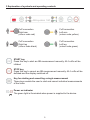
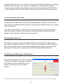
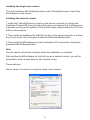
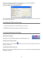
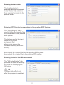
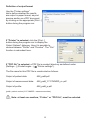
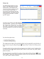
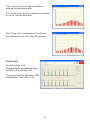
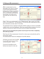
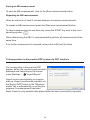
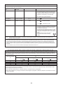
User instructions
boso ABI-system 100
0124
Contents
1 Contents of package
4
2 Minimum system requirements
4
3 Explanation of symbols and operating controls
5
4 Explanation of icons
6
5 Preliminary remarks
7
6 Important information
7
7 Ankle-Brachial Index (ABI)
8
8 Turning the device on
8
9 Installing the ABI system 100 software
8
• Installing the single user version
• Installing the network version
9
9
10 Installing the USB connection cable
10
11 Using the ABI-system 100 software
• Starting the program
• Calling up the Help function
• Configuration before first use
• Entering doctor’s data
• Entering GDT files for incorporation in the practice
EDP system
• Entering limits for the ABI assessment
• Definition of output format
• Patient tab
• Measurement tab
• Profiles tab
10
2
10
10
10
11
11
11
12
13
14
15
Contents
12 Preparing for an ABI measurement
16
• Attaching the cuff
• Assigning cuffs to limbs
16
16
13 Taking an ABI measurement
17
• Saving an ABI measurement
• Repeating an ABI measurement
18
18
14 Incorporation in practice EDP system via GDT interface
18
15 Cleaning the device and cuff
19
16 Disinfecting the apparatus
19
17 Warranty and customer service
19
18 Technical data
20
19 Instructions for disposal
20
20 Calibration checks - Testing instructions
• Function testing
• Testing of pressure circuit integrity and deviation of pressure display
• Safety seal
21
21 EMC notes for your boso ABI-system 100
22
22 Your notes
24
3
21
21
21
1 Contents of package
1
ABI-system 100
2
CA04 upper arm cuffs
2
CL04 ankle cuffs
1
ABI-system 100 software
1
USB cable
1
boso power supply unit art. no.: 410-7-154
1
Warranty certificate
1
User instructions
2 Minimum system requirements
•
Pentium II or higher
•
256 MB RAM
•
Graphics card
•
20 MB hard disk space
•
USB 1.0-interface
•
Microsoft Windows® XP, Windows® Vista™, Windows® 7
4
3 Explanation of symbols and operating controls
Cuff connection
Right arm
(colour code red)
Cuff connection
Left arm
(colour code yellow)
Cuff connection
Right leg
(colour code black)
Cuff connection
Left leg
(colour code green)
START key
Press this key to start an ABI measurement manually. All 4 cuffs will be
inflated.
STOP key
Press this key to cancel an ABI measurement manually. All 4 cuffs will be
deflated and the display switched off.
Key for starting and cancelling a single measurement
These keys enable the user to start and cancel individual measurements
of the limbs.
Power on indicator
The green light is illuminated when power is supplied to the device.
5
4 Explanation of icons
Read the user instructions
Protection class II device
Degree of protection against electric shock: type BF
USB 2.0 connection
0124
The CE mark documents compliance with the Medical Devices
Directive 93/42/EEC,
Notified body: DEKRA, 0124
Year of manufacture
Manufacturer
Potential equalisation
Do not dispose of this device in the domestic waste. For further
information see page 20.
6
5 Preliminary remarks
Your boso ABI-system 100 is an innovation on the market of blood pressure measurement technology. It provides a simple way of determining the ankle-brachial
index (ABI) and works on the oscillometric measurement principle. The pressure
variations (oscillations) caused by pulse waves and transmitted by the cuffs are
stored and evaluated by microprocessors. The great advantage of this type of
measurement is that there is no need for a microphone or amplifier which must be
positioned exactly if accurate results are to be obtained.
This system complies with the European directives on which the German Medical
Devices Act (CE mark: CE0124) is based and with European Standard EN 1060,
Part 1: “Non-invasive sphygmomanometers - General requirements” and Part 3:
“Supplementary requirements for electro-mechanical blood pressure measuring
systems”.
Calibration checks - every 2 years at the latest - can be performed either by
the manufacturer, or the trade measurement authorities, or persons who fulfil
the requirements of the legislation governing the operation of medical devices
(German Medical Devices Operator Ordinance section 6). Instructions for calibration checks can be found on page 21 of these user instructions.
Medical electrical apparatuses are subject to specific precautions as regards electromagnetic compatibility and must therefore be installed and operated according
to the EMC instructions given on pages 22 and 23.
6 Important information
• The same exclusion criteria apply for oscillometric ABI measurements as for
Doppler measurements.
• Cardiac arrhythmias can interfere with the accuracy of a measurement and produce incorrect readings. Interference can also occur in wearers of pacemakers
if they have a weak pulse. The blood pressure monitor will have no effect on the
pacemaker, however.
Do not use the apparatus in patients with severe heart failure.
Do not use the apparatus unattended in unconscious, helpless or unresponsive
persons.
Do not place the cuffs over open wounds, implanted stents or lymphoedema.
Allow an interval of at least 2 minutes between 2 consecutive measurements.
7
• Operating the device in the vicinity of strong electromagnetic fields (e.g. radiation
devices, mobile phones) can cause it to malfunction (see pages 22 and 23).
• The computer used for the analysis must meet the requirements of EN 60601-1.
• If the instrument is to be sold, ensure that these user instructions are enclosed.
7 Ankle-Brachial Index (ABI)
To determine the ABI value, the systolic blood pressure values of the arms and
legs must be measured. Blood pressure measurement values are given in mmHg
(mm of mercury).
The ABI is calculated as a quotient of the systolic pressure of the leg measurement (the mean pressure of the posterior and anterior tibial arteries) and the
higher systolic pressure of the arm measurements.
8 Turning the device on
The mains connection socket is located at the rear of the device. Use only the
boso power supply unit (order no. 410-7-154), as it produces a rectified output of
the correct polarity. Other commercially available power supply units can cause
damage to the electronic components, which will invalidate the warranty.
9 Installing the ABI-system 100 software
After the “ABI-system 100” CD is inserted,
a selection window will appear to enable
the software to be installed either as a
single user version or as a network
version.
¹ Deutsches Ärzteblatt | Vol. 102 | Issue 34-35 | 29 August 2005 | Knöchel-Arm-Index | C. Diehm, H. Darius, D. Pittrow, J. Allenberg
8
Installing the single user version
Click the [Installiere ABI-Software] button under "Einzelplatzversion" and follow
the dialogue on the screen.
Installing the network version
1.Install the Firebird-DB-server locally on the server computer by clicking the
[Installiere Firebird-DB-Server] button (this step is not required if a Firebird server
is already running on the system). With active firewall, please define the TCP-port
3050 as an exception.
2.Then install the database file “ABI.fdb” locally on the server computer in a directory of your choice by clicking the [Installiere Datenbankdatei] button.
3.Then install the ABI software on each workstation PC required by clicking the
[Installiere ABI-Software] button.
Note
You will need to reboot the computer when the installation is complete.
After starting the ABI software for the first time as a network version, you will be
prompted to enter access data (on this occasion only).
These data are:
Server name: Your server’s computer name in the network
9
Database file (Datenbankdatei): the target folder on the server\ABI.fdb
User name (Benutzername): sysdba (fixed)
Password (Passwort): masterkey (fixed)
The access data will be stored in the file ABI.ini; this information does not need to
be re-entered on start-up.
10 Installing the USB connection cable
• Connect the apparatus to a free USB port on your PC.
• WINDOWS automatically detects the USB connection
11 Using the ABI-system 100 software
Starting the program
Double click on the desktop symbol “boso ABI-system 100”
Calling up the Help function
Press the F1 key or the [Help]
tions as a PDF file.
button at any time to call up these user instruc-
Configuration before first use
Before starting the boso ABI system 100, you can enter the following settings
([Settings...] button).
10
Entering doctor’s data
The treating doctor’s
personal data can be entered
in the “Doctor” tab, which is
then used as the basis for the
printout footer.
Entering GDT files for incorporation in the practice EDP System
The “Import/Export” tab is
used to define the transfer files
for incorporation in the practice
EDP system.
The buttons next to the input
fields for the import
and export files
allow you to access the
Windows directory structure
directly.
boso import file = export file from the practice EDP system
boso export file = import file to the practice EDP system
Entering limits for the ABI assessment
The "ABI-calssification" tab
provides an option for altering
the limits for classifying the
ABI value.
NB:
Changes take effect only
after the program is restarted.
11
Definition of output format
Use the “Printer settings”
tab to define whether the results
are output in paper format, as print
preview and/or as a PDF document
by clicking on the appropriate [Print...]
button during the program run.
If "Printer” is selected, click the [Print...]
button during the program run to display the
Output Options" dialogue. Here it is possible to
choose between "Printer" and "Preview". The "File"
function is redundant here.
If "PDF file" is selected, a PDF file is created (directory as defined under
[Settings…] (Einstellungen...)
"Printer settings").
The file name for this PDF file is constructed as follows:
Output of patient data: ABI_pat#.pdf
Output of measurement data:
ABI_pat#_YYYYMMDD_m. pdf
Output of profile:
ABI_pat#_p.pdf
(pat# = patient number| YYYYMMDD = measurement date)
Note: at least one medium, “Printer” or "PDF file", must be selected.
12
Patient tab
On starting the program you are
taken to the ABI patient management screen. If the patient concerned is already registered, click
on the listing to select them. If
the program was started from the
practice system, the patient will be
automatically selected or created
by GDT import.
To add a new patient in the ABI software,
select the [New ...] button in the "Patient"
tab. “Name” and “Patient No.” are obligatory fields. The patient number is presented automatically, but can also be altered
manually.
You have the option here:
• to edit existing patients
• to delete existing patients
The measurement data of the selected patient can be exported to any directory in
Excel format using the [Export/Import] "Export Excel" button for further processing.
Complete patient data (master data and measurement data) can be transferred by
the [Export/Import] "Export Patient (ABI)" button in the format "abi_pat#" (pat# =
patient number)
The import function is available for reading in these data via [Export/Import] "Import
Patient (ABI)". Select the required patient number from the listed files in the format
"abi _pat#" (pat# = patient number).
13
Measurement tab
Previous measurements can be
viewed and new measurements
taken in the "Measurements” tab.
To display previous ABI measurements, select the required ABI
measurement in the “Date-Time”
field.
The following parameters will be displayed on screen (for the left and right side of
the body, respectively):
Sys Dia PP Pul Arr ABI Sys systolic blood pressure of the upper arm, displayed in red if >140 mmHg
diastolic blood pressure of the upper arm, displayed in red if > 90 mmHg
pulse pressure = difference between systole - diastole, displayed in red
if >54 mmHg
pulse value in 1/min
indicates whether a pulse rate irregularity of more than 25% occurred
during a measurement; red if “yes”, not if “no”)
Ankle-Brachial Index = quotient of the systolic pressure of the leg
measurement and the higher systolic pressure of the arm measurements,
displayed in red in line with the settings under [Settings...]
“ABI assessment” (default <0.9)
systolic blood pressure at the ankle
Note: If no measurement result is displayed for the systolic blood pressure at
the ankle, check the cuff and tubes and repeat the measurement. If still no measurement result is displayed, this may indicate a circulatory disturbance or medial
sclerosis. Further investigations are advisable.
Diff Arm Sys difference between the systolic values of the left upper arm and
the right upper arm, displayed in red if > 19 mmHg
Diff Arm Dia
difference between the diastolic values of the left upper arm and
the right upper arm, displayed in red if > 19 mmHg
Diff Leg Sys difference between the systolic values of the left ankle and the right ankle, displayed in red if > 19 mmHg
14
Click on one of the oscillation profiles to
enlarge the selected profile.
The “Pulse level / time” tab shows the oscillation curve over the time axis.
The “Pulse level / cuff pressure” tab shows
the oscillation curve over the cuff pressure.
Profiles tab
The ABI values of all
measurements are displayed graphically in the “Profiles” tab.
The colour mode is that set in “ABI
classification” (red: ABI < 0.9).
15
12 Preparing for an ABI measurement
The measurement must be performed with the patient supine to ensure
comparable blood pressure conditions in arms and legs.
The patient should rest for about 5 minutes before a measurement is
taken.
Attaching the cuff
The device should only be used with original boso CA04 or CL04 cuffs
Type
Circumference
Order no.
Upper arm cuff CA04
22 - 42 cm
143-4-768
Ankle cuff CL04
18 - 38 cm
143-4-769
The cuffs are colour-coded. Attach the individual cuffs to both upper arms and both
ankles according to their colour coding (matching the symbols next to the air connection sockets on the apparatus).
Attach the upper arm cuffs so that the lower edge of the cuff is
about 2-3 cm above the elbow joint.
The cuff should be positioned in such a way that the marking is
over the brachial artery.
Never place the metal ring over arteries, as this may produce an incorrect
reading.
Attach the ankle cuffs so that the lower edge of the cuff
is about 1-2 cm above the ankle joint.
The cuff should be positioned in such a way that the
white marking is over the posterior tibial artery.
Ensure that the cuff fits tightly at the ankle.
Assignment of cuffs to limbs
Check that the cuffs are correctly assigned to the individual limbs by individual
measurements of the right or left arm and right or left leg.
16
13 Taking an ABI measurement
A measurement can be
cancelled at any time by clicking
on the [Cancel measurement]
button in the software or pressing
the STOP key on the apparatus;
all the cuffs deflate automatically.
Alternatively, the cuffs can be
removed from the limbs at any
time.
Select “Start new measurement” in the “Measurements” tab or press the START
button on the apparatus. The ABI-system 100 starts the ABI measurement after a
short calibration process (about 3 seconds).
The apparatus has an intelligent automatic inflation system to ensure comfortable
inflation to the correct cuff pressure. When the correct inflation pressure has been
reached, the pump will switch off and the cuffs will deflate automatically.
At this point (if not before) the patient must keep all four limbs completely
still and may not talk.
After the end of the measurement, the built-in valves open automatically and the
cuffs deflate rapidly.
The measurement values are displayed in the ABI software.
Individual comments can be added
for each ABI measurement taken
via the [Remarks...] button.
Comments templates can be
defined and saved for later use.
17
Saving an ABI measurement
To save an ABI measurement, click on the [Save measurement] button.
Repeating an ABI measurement
Allow an interval or at least 2 minutes between successive measurements.
To repeat an ABI measurement press the [Start new measurement] button.
To take a measurement on one limb only, press the START key next to the corresponding symbol.
When determining the ABI it is recommended to perform all measurements at the
same time.
If no further measurement is required, remove the cuffs from the limbs.
14 Incorporation in the practice EDP system via GDT interface
For incorporation in the practice EDP
system, define the relevant communication
pathways and import/export file names
under [Settings ...] "Import/Export".
Import occurs automatically on program
start-up. Export is performed manually via
the [Export GDT] button in the “Measurements” tab or automatically on exiting the
program if a measurement has been
taken. Export is only possible after patient data has been successfully imported.
18
15 Cleaning the apparatus and cuff
Please use only a soft, dry cloth to clean the device.
Small stains on the cuff can be carefully removed with a damp cloth.
16 Disinfecting the apparatus
We recommend Antifect® Liquid disinfectant (Schülke&Mayr) to wipe the apparatus and cuffs for disinfection.
17 Warranty and customer service
For details of the warranty conditions, please consult the warranty certificate supplied.
A claim under warranty will only be accepted if the warranty certificate, completed
and stamped by the dealer, is returned with the device.
For warranty and repair work, please send the device, carefully packaged and with
sufficient postage, to your authorised dealer or directly to:
BOSCH + SOHN GmbH u. Co. KG
Bahnhofstraße 64
D-72417 Jungingen
19
18 Technical data
Measurement principle:
oscillometric
Measurement range:
40 to 240 mmHg
Cuff pressure:
0 to 300 mmHg
Maximum deviation of cuff pressure measurement:
± 3 mmHg
Operating conditions:
Environmental temperature 10 to 40°C
Relative humidity 10 to 85%
Transport and storage conditions:
Environmental temperature -5°C to 50°C
Relative humidity max. 85%
Power supply:
DC 5 V power supply unit, 2.7 A, AC 100240 V, 50-60 Hz, order no.: 410-7-154
Weight:
3.68 kg without power supply unit
Dimensions (W x H x D):
458 mm x 83 mm x 290 mm
Classification:
Clinical test (DIN 58130):
Subject to technical modifications.
Protection class II (Symbol
Type BF (Symbol :
)
)
accuracy complies with the requirements of EN 1060 part 3
19 Instructions for disposal
This apparatus falls within the scope of EC Directive 2002/96/EC (WEEE). It is
not registered for use in private households and disposal via communal collection
sites for obsolete electrical apparatus is prohibited. Bosch + Sohn has commissioned a company to dispose of the apparatus safely and legally. Please refer to the
address mentioned at the end of these user instructions for further information.
20
20 Calibration checks – Testing instructions
Function testing
Function testing of the device can only be carried out on a person or with a suitable simulator.
Testing of pressure circuit integrity and deviation of pressure display
1.) Use the [Settings …] button in
the "Patient" tab to select
“Test mode" and click on the
“Start” button.
2.)
After a short calibration process the apparatus will be in test mode. The
current pressure will be displayed in the corresponding ABI-system 100 software fields.
3.)
Perform the usual test for deviation of pressure display and pressure cir
cuit integrity (allow a set-up time of at least 30 seconds for the cuff).
4.)
Run the test for all 4 limbs.
5.)
Exit test by pressing the “Finish test” button.
Safety seal
As a safeguard, the upper and lower parts of the housing can be joined with a
safety seal.
21
21 EMC notes for your boso ABI-system 100
EMC-notes for your ABI-system 100
Medical Electrical Equipment needs special precautions regarding EMC and needs to be installed and put into service according the EMC information provided in the following.
Portable and mobile RF communication equipment (e.g. cell phones) can affect Medical Electrical Equipment.
The use of accessories and cables other than those specified (other than boso original parts) may result in increased emissions or decreased immunity of the unit.
Guidance and manufacturer’s declaration – electromagnetic emissions
The boso unit is intended for use in the electromagnetic environment specified below. The customer of the user of the boso unit should
assure that it is used in such an environment.
Emissions test
Compliance
Electromagnetic environment – guidance
RF emissions
CISPR 11
Group 1
The boso unit uses RF energy only for its internal function. Therefore, its RF emissions are very low and are not likely to cause any
interference in nearby electronic equipment.
RF emissions
CISPR 11
Class B
Harmonic emissions
IEC 61000-3-2
Class A
The boso unit is suitable for use in all establishments, including
domestic establishments and those directly connected to the public
low-voltage power supply network that supplies buildings used for
domestic purposes.
Voltage fluctuations/flicker
emissions IEC 61000-3-3
Complies
Guidance and manufacturer’s declaration – electromagnetic immunity
The boso unit is intended for use in the electromagnetic environment specified below. The customer or the user of the boso unit should
assure that it is used in such an environment.
Immunity
test
IEC 60601
test level
Compliance level
Electrostatic
discharge (ESD)
IEC 61000-4-2
± 6 kV
contact
± 6 kV
contact
± 8 kV
air
± 8 kV
air
Electrical fast
transient/burst
IEC 61000-4-4
± 2 kV for power
supply lines
± 2 kV for power
supply lines
± 1 kV
for input/output
lines
± 1 kV
for input/output
lines
Surge
IEC 61000-4-5
± 1 kV
differential mode
± 1 kV
differential mode
±2 kV
common mode
±2 kV
common mode
< 5% UT
(> 95% dip in UT)
for 0,5 cycle
< 5% UT
(> 95% dip in UT)
for 0,5 cycle
40% UT
(60% dip in UT)
for 5 cycles
40% UT
(60% dip in UT)
for 5 cycles
70% UT
(30% dip in UT)
for 25 cycles
70% UT
(30% dip in UT)
for 25 cycles
< 5% UT
(> 95% dip in UT)
for 5 s
< 5% UT
(> 95% dip in UT)
for 5 s
3 A/m
3 A/m
Voltage dips,
short interruptions and
voltage variations
on power supply
input lines
IEC 61000-4-11
Power frequency
(50/60 Hz)
magnetic field
IEC 61000-4-8
Electromagnetic environment – guidance
Floors should be wood, concrete or ceramic tile.
If floors are covered with synthetic material, the
relative humidity should be at least 30%.
Mains power quality should be that of a typical commercial or hospital environment.
Mains power quality should be that of a typical commercial or hospital environment.
Mains power quality should be that of a typical commercial or hospital environment. If the user of the boso
unit requires continued operation during power mains
interruptions, it is recommended that the boso unit has
to be powered from a uninterruptible power supply or a
battery.
NOTE : UT is the a.c. mains voltage prior to application of the test level.
22
Guidance and manufacturer’s declaration – electromagnetic immunity
The boso unit is intended for use in the electromagnetic environment specified below. The customer or the user of the boso unit should
assure that it is used in such an environment.
Immunity
test
IEC 60601
test level
Compliance level
Electromagnetic environment – guidance
Portable and mobile RF communications equipment should be used no closer to any party of the
boso unit, including cables, than the recommended
separation distance calculated from the equation
applicable to the frequency of the transmitter.
Recommended separation distance:
Conducted RF
IEC 61000-4-6
3 V rms
150 kHz to 80 MHz
3 V rms
d = 1,2
Radiated RF
IEC 61000-4-3
3 V/m
80 MHz to 2,5 GHz
3 V/m
d = 1,2 P
80 MHz to 800 MHz
d = 2,3
800 MHz to 2,5 GHz
P
P
where P is the maximum output power rating of the
transmitter in watts (W) according to the transmitter
manufacturer and d is the recommended separation distance in metres (m).
Field strengths from fixed RF transmitters, as determined by an electromagnetic site survey, a should
be less than the compliance level in each frequency
range.b
Interference may occur in the vicinity of
equipment marked with the following
symbol:
NOTE 1 At 80 MHz and 800 MHz, the higher frequency range applies.
NOTE 2 These guidelines may not apply in all situations. Electromagnetic propagation is affected by absorption and reflection from
structures, objects and people.
a
Field strengths from fixed transmitters, such as base stations for radio (cellular/cordless) telephones and land mobile radios, amateur
radio, AM and FM radio broadcast and TV broadcast cannot be predicted theoretically with accuracy. To assess the electromagnetic
environment due to fixed RF transmitters, an electromagnetic site survey should be considered. If the measured field strength in the
location in which the boso unit is used exceeds the applicable RF compliance level above, the boso unit should be observed to verify
normal operation. If abnormal performance is observed, additional measures may be necessary, such als re-orienting or relocating the
boso unit.
b
Over the frequency range 150 kHz to 80 MHz, field strengths should be less than 3 V/m.
Recommended separation distances between portable and mobile RF communications equipment and the boso unit
The boso unit is intended for use in an electromagnetic environment in which radiated RF disturbances are controlled. The customer or the
user of the boso unit can help prevent electromagnetic interference by maintaining a minimum distance between portable and mobile RF
communications equipment (transmitters) and the boso unit as recommended below, according the the maximum output power of the communications equipment.
Separation distance according to frequency of transmitter
m
Rated maximum output
power of transmitter
W
150 kHz to 80 MHz
80 MHz to 800 MHz
800 MHz to 2,5 GHz
0,01
0,1
1
10
100
d = 1,2 P
0,12
0,38
1,2
3,8
12
d = 1,2 P
0,12
0,38
1,2
3,8
12
d = 2,3 P
0,23
0,73
2,3
7,3
23
For transmitter rated at a maximum output power not listed above, the recommended separation distance d in metres (m) can be estimated
using the equation applicable to the frequency of the transmitter, where p is the maximum output power rating of the transmitter in watts
(W) according the the transmitter manufacturer.
NOTE 1 At 80 MHz and 800 MHz, the separation distance for the higher frequency range applies.
NOTE 2 These guidelines may not apply in all situations. Electromagnetic propagation is affected by absorption and reflection from structures, objects and people.
23
22 Your notes
24
Your notes
25
Your notes
26
Your notes
27
Subject to change without prior notification. Omissions and errors
excepted. (08/05/2012)
BOSCH + SOHN GmbH u. Co. KG
Bahnhofstraße 64 • 72417 Jungingen • Germany
Telefon: +49 (0) 74 77 / 92 75-0 • Fax: +49 (0) 74 77 / 10 21
www.boso.de • mail: [email protected]