1
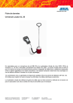
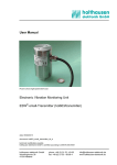
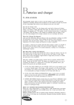
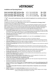
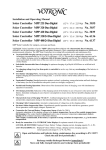
User Manual
High Voltage Testing Set
PGK 25
Ident. no. 822-001
10/06
BAUR Prüf- und Messtechnik GmbH
Raiffeisenstrasse 8, A-6832 Sulz / Austria
e-mail: [email protected]
internet: http://www.baur.at
0-1
Tel +43 / 55 22 / 49 41-0
Fax +43 / 55 22 / 49 4 13
0-2
Guide to this Operating Instruction, Copyright, Preface, Safety Precautions
Guide to this Operating Instruction
Observe info signs!
For fast finding of important information the corresponding text
passages are marked with symbols (symbols not stated here are
self-explaining):
More and special information concerning the respective subject are
available from BAUR.
Important unit information!
In any case, read carefully!
☞
Important information text.
Copyright
© Copyright by BAUR
Subject to modification!
Preface
© BAUR Prüf- und Messtechnik GmbH, A-6832-Sulz / Austria
All rights reserved.
No part of this publication may be reproduced, transmitted, stored
in a data processing system or translated into another language
without the written permission of BAUR / Sulz, Austria.
In the interest of our customers we reserve the rights for
modifications due to technical progress.
Illustrations, descriptions and delivery content are therefore not
binding.
This manual contains all information necessary for the correct
handling and use of the PGK 25 High Voltage Testing Set. Before
using the PGK 25, please read carefully this Operating Instruction.
If you have any question, please contact directly:
BAUR Prüf- und Messtechnik GmbH, Raiffeisenstrasse 8
A-6832 Sulz / Austria
Phone +43 / 55 22 / 49 41-0
Fax +43 / 55 22 / 49 41 3
or refer to your nearest BAUR representative.
Safety Precautions
Please read now
and avoid damage
and injury later!
- The PGK 25 High Voltage Testing Set is built in accordance
with today’s state of engineering and is safe to operate.
Individual components and the finished unit are inspected
continually by our qualified staff within the framework of our
Quality Assurance Provisions. Each unit is subjected to
thorough testing prior to shipment.
Continued
0-3
Safety Precautions, Warranty
Safety Precautions, Continued
- It is imperative to every person who is involved with the
installation, start-up, operation and maintenance to have read
and understood the complete Operating Instructions.
- It is the responsibility of the customer to ensure that only
authorized persons may be allowed to use the PGK 25.
Only authorized personnel!
- The user
• is qualified and properly instructed and has the necessary
experience.
• knows the relevant standards, accident prevention rules and
operating conditions.
• is able to carry out the necessary operations and is aware of
the possible dangers involved.
• must immediately inform his superior about any conditions of
the unit that could affect safety.
Use the PGK 25 as directed!
The PGK 25 is a High Voltage Testing Set for insulation testing of
cables, windings and insulators.
☞
Warranty
The local safety and accident prevention regulations are
always applicable to the operation of the PGK 25.
At the customer’s written request we undertake to repair or replace
at our discretion and as quickly as possible all parts that become
faulty or useless as the demonstrable result of poor material, faulty
design or defective execution.
12 month warranty time
The 12 month warranty time starts with delivery.
We shall bear the costs of any faulty parts requiring replacement,
but not the costs of transport to us and back to the customer, nor the
costs of packing and insurance! We shall not be liable for any
damage resulting from normal wear and tear, improper handling,
non-observance of Operating Instructions and safety regulations.
We shall also refuse to accept any liability if the customer carries out
repairs or changes to the unit himself or has others carry out them!
The warranty does not cover damage in transit, batteries, fuses and
any readjustments in accordance with the Operating Instructions!
We draw attention in addition to the ‘General Terms of Sales and
Delivery’ of:
BAUR Prüf- und Messtechnik GmbH, Raiffeisenstrasse 8
A-6832-Sulz / Austria
0-4
Contents
Contents
1. Operating Elements ......................................................................... 1-1
2. Packing and Shipping ...................................................................... 2-1
Damage during transport ............................................................ 2-1
3. Power supply / Power selection ..................................................... 3-1
Maintenance ............................................................................... 3-1
General rule ................................................................................ 3-1
4. Setting into operation ...................................................................... 4-1
Plotter connector ......................................................................... 4-2
5. Guard Connection ............................................................................ 5-1
General ....................................................................................... 5-1
Current measuring device ........................................................... 5-2
Application .................................................................................. 5-3
6. Technical Data .................................................................................. 6-1
General ....................................................................................... 6-1
Mechanical Data ......................................................................... 6-2
Standard accessories ................................................................. 6-2
Special accessories .................................................................... 6-2
7. Insulation resistance chart .............................................................. 7-1
0-5
Notes
○
○
○
○
○
○
○
○
○
○
○
○
○
○
○
○
○
○
○
○
○
○
○
○
○
○
○
○
○
○
○
○
○
○
○
○
○
○
○
○
○
○
○
○
○
○
○
○
○
○
○
○
○
○
○
○
○
○
○
○
○
○
○
○
○
○
○
○
○
○
○
○
○
○
○
○
○
○
○
○
○
○
○
○
○
○
○
○
○
○
○
○
○
○
○
○
○
○
○
○
○
○
○
○
○
○
○
○
○
○
○
○
○
○
○
○
○
○
○
○
○
○
○
○
○
○
○
○
○
○
○
○
○
○
○
○
○
○
○
○
○
○
○
○
○
○
○
○
○
○
○
○
○
○
○
○
○
○
○
○
○
○
○
○
○
○
○
○
○
○
○
○
○
○
○
○
○
○
○
○
○
○
○
○
○
○
○
○
○
○
○
○
○
○
○
○
○
○
○
○
○
○
○
○
○
○
○
○
○
○
○
○
○
○
○
○
○
○
○
○
○
○
○
○
○
○
○
○
○
○
○
○
○
○
○
○
○
○
○
○
○
○
○
○
○
○
○
○
○
○
○
○
○
○
○
○
○
○
○
○
○
○
○
○
○
○
○
○
○
○
○
○
○
○
○
○
○
○
○
○
○
○
○
○
○
○
○
○
○
○
○
○
○
○
○
○
○
○
○
○
○
○
○
○
○
○
○
○
○
○
○
○
○
○
○
○
○
○
○
○
○
○
○
○
○
○
○
○
○
○
○
○
○
○
○
○
○
○
○
○
○
○
○
○
○
○
○
○
○
○
○
○
○
○
○
○
○
○
○
○
○
○
○
○
○
○
○
○
○
○
○
○
○
○
○
○
○
○
○
○
○
○
○
○
○
○
○
○
○
○
○
○
○
○
○
○
○
○
○
○
○
○
○
○
○
○
○
○
○
○
○
○
○
○
○
○
○
○
○
○
○
○
○
○
○
○
○
○
○
○
○
○
○
○
○
○
○
○
○
○
○
○
○
○
○
○
○
○
○
○
○
○
○
○
○
○
○
○
○
○
○
○
○
○
○
○
○
○
○
○
○
○
○
○
○
○
○
○
○
○
○
○
○
○
○
○
○
○
○
○
○
○
○
○
○
○
○
○
○
○
○
○
○
○
○
○
○
○
○
○
○
○
○
○
○
○
○
○
○
○
○
○
○
○
○
○
○
○
○
○
○
○
○
○
○
○
○
○
○
○
○
○
○
○
○
○
○
○
○
○
○
○
○
○
○
○
○
○
○
○
○
○
○
○
○
○
○
○
○
○
○
○
○
○
○
○
○
○
○
○
○
○
○
○
○
○
○
○
○
○
○
○
○
○
○
○
○
○
○
○
○
○
○
○
○
○
○
○
○
○
○
○
○
○
○
○
○
○
○
○
○
○
○
○
○
○
○
○
○
○
○
○
○
○
○
○
○
○
○
○
○
○
○
○
○
○
○
○
○
○
○
○
○
○
○
○
○
○
○
○
○
○
○
○
○
○
○
○
○
○
○
○
○
○
○
○
○
○
○
○
○
○
○
○
○
○
○
○
○
○
○
○
○
○
○
○
○
○
○
○
○
○
○
○
○
○
○
○
○
○
○
○
○
○
○
○
○
○
○
○
○
○
○
○
○
○
○
○
○
○
○
○
○
○
○
○
○
○
○
○
○
○
○
○
○
○
○
○
○
○
○
○
○
○
○
○
○
○
○
○
○
○
○
○
○
○
○
○
○
○
○
○
○
○
○
○
○
○
○
○
○
○
○
○
○
○
○
○
○
○
○
○
○
○
○
○
○
○
○
○
○
○
○
○
○
○
○
○
○
○
○
○
○
○
○
○
○
○
○
○
○
○
○
○
○
○
○
○
○
○
○
○
○
○
○
○
0-6
○
○
○
○
○
○
○
○
○
○
○
○
○
○
○
○
○
○
○
○
○
○
○
○
○
○
○
○
○
○
○
○
○
○
○
○
○
○
1. Operating Elements
1. Operating Elements
13
12
10
11
9
8
7
1
2
3
4
5 14 15 6
1
Push-button switch for battery test
2
Selector switch 0 - 5 kV or 0 - 25 kV
3
Voltage regulator with 0-locking
4
Range selector switch for current indication
5
Operating switch with timer and discharge unit
6
High voltage output with controlling contact
7
Connector for protective earth cable
8
Mains connector with power selector and fuses
9
Connectors for external battery (12 V)
10
Connector for current range plotter
11
H.V. control lamp
12
µA - meter
13
kV - meter with indication for battery test
Option: Guard connection
14
Operating mode switch for current measurement
15
Terminal for current measurement
1-1
1. Operating Elements
Notes
○
○
○
○
○
○
○
○
○
○
○
○
○
○
○
○
○
○
○
○
○
○
○
○
○
○
○
○
○
○
○
○
○
○
○
○
○
○
○
○
○
○
○
○
○
○
○
○
○
○
○
○
○
○
○
○
○
○
○
○
○
○
○
○
○
○
○
○
○
○
○
○
○
○
○
○
○
○
○
○
○
○
○
○
○
○
○
○
○
○
○
○
○
○
○
○
○
○
○
○
○
○
○
○
○
○
○
○
○
○
○
○
○
○
○
○
○
○
○
○
○
○
○
○
○
○
○
○
○
○
○
○
○
○
○
○
○
○
○
○
○
○
○
○
○
○
○
○
○
○
○
○
○
○
○
○
○
○
○
○
○
○
○
○
○
○
○
○
○
○
○
○
○
○
○
○
○
○
○
○
○
○
○
○
○
○
○
○
○
○
○
○
○
○
○
○
○
○
○
○
○
○
○
○
○
○
○
○
○
○
○
○
○
○
○
○
○
○
○
○
○
○
○
○
○
○
○
○
○
○
○
○
○
○
○
○
○
○
○
○
○
○
○
○
○
○
○
○
○
○
○
○
○
○
○
○
○
○
○
○
○
○
○
○
○
○
○
○
○
○
○
○
○
○
○
○
○
○
○
○
○
○
○
○
○
○
○
○
○
○
○
○
○
○
○
○
○
○
○
○
○
○
○
○
○
○
○
○
○
○
○
○
○
○
○
○
○
○
○
○
○
○
○
○
○
○
○
○
○
○
○
○
○
○
○
○
○
○
○
○
○
○
○
○
○
○
○
○
○
○
○
○
○
○
○
○
○
○
○
○
○
○
○
○
○
○
○
○
○
○
○
○
○
○
○
○
○
○
○
○
○
○
○
○
○
○
○
○
○
○
○
○
○
○
○
○
○
○
○
○
○
○
○
○
○
○
○
○
○
○
○
○
○
○
○
○
○
○
○
○
○
○
○
○
○
○
○
○
○
○
○
○
○
○
○
○
○
○
○
○
○
○
○
○
○
○
○
○
○
○
○
○
○
○
○
○
○
○
○
○
○
○
○
○
○
○
○
○
○
○
○
○
○
○
○
○
○
○
○
○
○
○
○
○
○
○
○
○
○
○
○
○
○
○
○
○
○
○
○
○
○
○
○
○
○
○
○
○
○
○
○
○
○
○
○
○
○
○
○
○
○
○
○
○
○
○
○
○
○
○
○
○
○
○
○
○
○
○
○
○
○
○
○
○
○
○
○
○
○
○
○
○
○
○
○
○
○
○
○
○
○
○
○
○
○
○
○
○
○
○
○
○
○
○
○
○
○
○
○
○
○
○
○
○
○
○
○
○
○
○
○
○
○
○
○
○
○
○
○
○
○
○
○
○
○
○
○
○
○
○
○
○
○
○
○
○
○
○
○
○
○
○
○
○
○
○
○
○
○
○
○
○
○
○
○
○
○
○
○
○
○
○
○
○
○
○
○
○
○
○
○
○
○
○
○
○
○
○
○
○
○
○
○
○
○
○
○
○
○
○
○
○
○
○
○
○
○
○
○
○
○
○
○
○
○
○
○
○
○
○
○
○
○
○
○
○
○
○
○
○
○
○
○
○
○
○
○
○
○
○
○
○
○
○
○
○
○
○
○
○
○
○
○
○
○
○
○
○
○
○
○
○
○
○
○
○
○
○
○
○
○
○
○
○
○
○
○
○
○
○
○
○
○
○
○
○
○
○
○
○
○
○
○
○
○
○
○
○
○
○
○
○
○
○
○
○
○
○
○
○
○
○
○
○
○
○
○
○
○
○
○
○
○
○
○
○
○
○
○
○
○
○
○
○
○
○
○
○
○
○
○
○
○
○
○
○
○
○
○
○
○
○
○
○
○
○
○
○
○
○
○
○
○
○
○
○
1-2
○
○
○
○
○
○
○
○
○
○
○
○
○
○
○
○
○
○
○
○
○
○
○
○
○
○
○
○
○
○
○
○
○
○
○
○
○
○
2. Packing and Shipping
2. Packing and Shipping
The Test Set is shipped in robust cardboard cartons. If Test Set is
not used immediately, store in carton in dry rooms!
Damage during transport
Complaints concerning damage should be made to us without
delay, using a standard damage claims form.
Confirmation of visible damage should immediately be obtained
from the carrier. The extent and probable cause of the damage
should be stated.
If damage is discovered during unpacking, contact the responsible
transportation company immediately. Request a written loss
assessment and make them responsible for the damage.
We also refer to the ’General Terms of Sales and Delivery’ of:
BAUR Prüf- und Messtechnik GmbH, A-6832 Sulz / Austria
2-1
2. Packing and Shipping
Notes
○
○
○
○
○
○
○
○
○
○
○
○
○
○
○
○
○
○
○
○
○
○
○
○
○
○
○
○
○
○
○
○
○
○
○
○
○
○
○
○
○
○
○
○
○
○
○
○
○
○
○
○
○
○
○
○
○
○
○
○
○
○
○
○
○
○
○
○
○
○
○
○
○
○
○
○
○
○
○
○
○
○
○
○
○
○
○
○
○
○
○
○
○
○
○
○
○
○
○
○
○
○
○
○
○
○
○
○
○
○
○
○
○
○
○
○
○
○
○
○
○
○
○
○
○
○
○
○
○
○
○
○
○
○
○
○
○
○
○
○
○
○
○
○
○
○
○
○
○
○
○
○
○
○
○
○
○
○
○
○
○
○
○
○
○
○
○
○
○
○
○
○
○
○
○
○
○
○
○
○
○
○
○
○
○
○
○
○
○
○
○
○
○
○
○
○
○
○
○
○
○
○
○
○
○
○
○
○
○
○
○
○
○
○
○
○
○
○
○
○
○
○
○
○
○
○
○
○
○
○
○
○
○
○
○
○
○
○
○
○
○
○
○
○
○
○
○
○
○
○
○
○
○
○
○
○
○
○
○
○
○
○
○
○
○
○
○
○
○
○
○
○
○
○
○
○
○
○
○
○
○
○
○
○
○
○
○
○
○
○
○
○
○
○
○
○
○
○
○
○
○
○
○
○
○
○
○
○
○
○
○
○
○
○
○
○
○
○
○
○
○
○
○
○
○
○
○
○
○
○
○
○
○
○
○
○
○
○
○
○
○
○
○
○
○
○
○
○
○
○
○
○
○
○
○
○
○
○
○
○
○
○
○
○
○
○
○
○
○
○
○
○
○
○
○
○
○
○
○
○
○
○
○
○
○
○
○
○
○
○
○
○
○
○
○
○
○
○
○
○
○
○
○
○
○
○
○
○
○
○
○
○
○
○
○
○
○
○
○
○
○
○
○
○
○
○
○
○
○
○
○
○
○
○
○
○
○
○
○
○
○
○
○
○
○
○
○
○
○
○
○
○
○
○
○
○
○
○
○
○
○
○
○
○
○
○
○
○
○
○
○
○
○
○
○
○
○
○
○
○
○
○
○
○
○
○
○
○
○
○
○
○
○
○
○
○
○
○
○
○
○
○
○
○
○
○
○
○
○
○
○
○
○
○
○
○
○
○
○
○
○
○
○
○
○
○
○
○
○
○
○
○
○
○
○
○
○
○
○
○
○
○
○
○
○
○
○
○
○
○
○
○
○
○
○
○
○
○
○
○
○
○
○
○
○
○
○
○
○
○
○
○
○
○
○
○
○
○
○
○
○
○
○
○
○
○
○
○
○
○
○
○
○
○
○
○
○
○
○
○
○
○
○
○
○
○
○
○
○
○
○
○
○
○
○
○
○
○
○
○
○
○
○
○
○
○
○
○
○
○
○
○
○
○
○
○
○
○
○
○
○
○
○
○
○
○
○
○
○
○
○
○
○
○
○
○
○
○
○
○
○
○
○
○
○
○
○
○
○
○
○
○
○
○
○
○
○
○
○
○
○
○
○
○
○
○
○
○
○
○
○
○
○
○
○
○
○
○
○
○
○
○
○
○
○
○
○
○
○
○
○
○
○
○
○
○
○
○
○
○
○
○
○
○
○
○
○
○
○
○
○
○
○
○
○
○
○
○
○
○
○
○
○
○
○
○
○
○
○
○
○
○
○
○
○
○
○
○
○
○
○
○
○
○
○
○
○
○
○
○
○
○
○
○
○
○
○
○
○
○
○
○
○
○
○
○
○
○
○
○
○
○
○
○
○
○
○
○
○
○
○
○
○
○
○
○
○
○
○
○
○
○
○
○
○
○
○
○
○
○
○
○
○
○
○
○
○
○
○
○
○
○
○
○
○
○
2-2
○
○
○
○
○
○
○
○
○
○
○
○
○
○
○
○
○
○
○
○
○
○
○
○
○
○
○
○
○
○
○
○
○
○
○
○
○
○
3. Power supply / Power selection
3. Power supply / Power selection
The unit is factory-set to 220 -230 V. If the unit is operated under
different power, remove power cord and open cover of voltage
selector using a small screwdriver. Now the voltage selector drum
can be withdrawn and inserted again after selecting.
Check also the inserted fuses and the amperage as shown on the
typeplate. Close cover by simply pressing on it.
Battery operation should only be performed with fully charged
battery.
Maintenance
Units with built in battery must be maintained. Since batteries
discharge even when instrument is not in use, batteries must be
recharged occassionally.
General rule
Charge batteries after approx.30 days as well as before instrument
is put into operation.
☞
Discharged Dryfit batteries should not be put in storage.
3-1
3. Power supply / Power selection
Notes
○
○
○
○
○
○
○
○
○
○
○
○
○
○
○
○
○
○
○
○
○
○
○
○
○
○
○
○
○
○
○
○
○
○
○
○
○
○
○
○
○
○
○
○
○
○
○
○
○
○
○
○
○
○
○
○
○
○
○
○
○
○
○
○
○
○
○
○
○
○
○
○
○
○
○
○
○
○
○
○
○
○
○
○
○
○
○
○
○
○
○
○
○
○
○
○
○
○
○
○
○
○
○
○
○
○
○
○
○
○
○
○
○
○
○
○
○
○
○
○
○
○
○
○
○
○
○
○
○
○
○
○
○
○
○
○
○
○
○
○
○
○
○
○
○
○
○
○
○
○
○
○
○
○
○
○
○
○
○
○
○
○
○
○
○
○
○
○
○
○
○
○
○
○
○
○
○
○
○
○
○
○
○
○
○
○
○
○
○
○
○
○
○
○
○
○
○
○
○
○
○
○
○
○
○
○
○
○
○
○
○
○
○
○
○
○
○
○
○
○
○
○
○
○
○
○
○
○
○
○
○
○
○
○
○
○
○
○
○
○
○
○
○
○
○
○
○
○
○
○
○
○
○
○
○
○
○
○
○
○
○
○
○
○
○
○
○
○
○
○
○
○
○
○
○
○
○
○
○
○
○
○
○
○
○
○
○
○
○
○
○
○
○
○
○
○
○
○
○
○
○
○
○
○
○
○
○
○
○
○
○
○
○
○
○
○
○
○
○
○
○
○
○
○
○
○
○
○
○
○
○
○
○
○
○
○
○
○
○
○
○
○
○
○
○
○
○
○
○
○
○
○
○
○
○
○
○
○
○
○
○
○
○
○
○
○
○
○
○
○
○
○
○
○
○
○
○
○
○
○
○
○
○
○
○
○
○
○
○
○
○
○
○
○
○
○
○
○
○
○
○
○
○
○
○
○
○
○
○
○
○
○
○
○
○
○
○
○
○
○
○
○
○
○
○
○
○
○
○
○
○
○
○
○
○
○
○
○
○
○
○
○
○
○
○
○
○
○
○
○
○
○
○
○
○
○
○
○
○
○
○
○
○
○
○
○
○
○
○
○
○
○
○
○
○
○
○
○
○
○
○
○
○
○
○
○
○
○
○
○
○
○
○
○
○
○
○
○
○
○
○
○
○
○
○
○
○
○
○
○
○
○
○
○
○
○
○
○
○
○
○
○
○
○
○
○
○
○
○
○
○
○
○
○
○
○
○
○
○
○
○
○
○
○
○
○
○
○
○
○
○
○
○
○
○
○
○
○
○
○
○
○
○
○
○
○
○
○
○
○
○
○
○
○
○
○
○
○
○
○
○
○
○
○
○
○
○
○
○
○
○
○
○
○
○
○
○
○
○
○
○
○
○
○
○
○
○
○
○
○
○
○
○
○
○
○
○
○
○
○
○
○
○
○
○
○
○
○
○
○
○
○
○
○
○
○
○
○
○
○
○
○
○
○
○
○
○
○
○
○
○
○
○
○
○
○
○
○
○
○
○
○
○
○
○
○
○
○
○
○
○
○
○
○
○
○
○
○
○
○
○
○
○
○
○
○
○
○
○
○
○
○
○
○
○
○
○
○
○
○
○
○
○
○
○
○
○
○
○
○
○
○
○
○
○
○
○
○
○
○
○
○
○
○
○
○
○
○
○
○
○
○
○
○
○
○
○
○
○
○
○
○
○
○
○
○
○
○
○
○
○
○
○
○
○
○
○
○
○
○
○
○
○
○
○
○
○
○
○
○
○
○
○
○
○
○
○
○
○
○
○
○
○
○
○
○
○
○
○
○
○
○
○
○
○
○
○
○
○
○
○
○
○
○
○
○
○
○
○
○
○
○
○
○
○
○
○
○
○
○
○
○
○
○
○
○
○
○
○
○
○
○
○
○
○
○
3-2
○
○
○
○
○
○
○
○
○
○
○
○
○
○
○
○
○
○
○
○
○
○
○
○
○
○
○
○
○
○
○
○
○
○
○
○
○
○
4. Setting into operation
4.1 Setting into operation
The PGK 25 is designed in such a way, that no output current is
generated which could be harmful in case of body contact. In the
process of testing capacitive type test objects however, dangerous
charges may occur. In tests where charges of 350 mJ or higher are
stored in items with which persons could make contact, special
protection measures are required to avoid direct or indirect contact
with live parts.
1)
Connect instrument with protective earth lead (461-308) via
protective earth connector (7) with station earth.
2)
Connect instrument and test object with H.V. cable (460-437).
3)
Mains operation:
Connect instrument with power cord (554-005). Please pay
attention to selected mains voltage!
Battery operation:
Check battery voltage by pressing push-button switch (1). The state
of charge of the battery will be indicated by the kV meter. In battery
test, the needle must be within the marked range.
4)
Set range selector switch (2) to the desired range (0-5 kV or
0-25 kV).
5)
Set voltage regulator (3) to "0".
(Otherwise the instrument cannot be turned on).
6)
Set range selector switch (4) of amperemeter to maximum value
(10 mA).
7)
The high voltage will be turned on by the timer (5) and the control
lamp (11) will be on.
8)
Now the high voltage can be set to the desired value by turning the
voltage regulator (3). The current range selector switch (4) can also
be adjusted.
9)
Only now the timer (5) should be set to the desired operating time.
The insulation resistance of the test object, resulting from current
and voltage can now be determined by using the attached chart.
10) Instrument shutdown; turn timer (5) completely counter-clockwise;
H.V. control lamp (11) will be off.
11) Once the H.V. lamp is off, the integrated discharge unit will
automatically be activated. The connected test objects (capacities)
will be discharged slowly via a resistor (125 k Ohms). The
discharge time at 6 μF is approximately 5 seconds.
12) For measurements of very low current values:
☞
recommended way of application:
- operate the PGK in battery mode
- use the option „Charging current limitation for high capacities“
For using of the option „Charging current limitation for high
capacities“, the following points need to be considered:
- the voltage indication error is maximum 125V (at 1mA)
- The discharging periods need to be doubled
Before touching the test object short-circuit test object and connect it
to earth!
4-1
4. Setting into operation
4.2 Plotter connector
It is possible to plot the test current as function of time to a
external plotter via the plotter connector (10) of the PGK 25. The
output voltage is function of the current range (4) 200mV at fullscale deflection of the internal ampermeter
4-2
5. Guard Connection
5. Guard Connection
General
H.V. connection
Starting with series 16 of the PGK 25, a Guard connection is
provided as an option. With the feature, a variety of measurements
jobs can be performed where the connections for the shield and
current measuring terminal are separately mounted.
Ω / 200W are integrated
In the Guard option, resistors with 1 kΩ
in the current measuring lead (461-408) and in the shield
connection of the H.V. lead. These resistors serve for the
protection of the instrument against transient voltages.
The resistors in the connection leads must be checked for
damage after high voltage breakdown of test objects with high
capacity (> 0.5 µF) or heavy mechanical stress.
5-1
5. Guard Connection
Current measuring device
Shield
The current measuring device of the PGK 25 has 5 measuring
ranges from 1 µA to 10 mA. Due to the separately mounted
connectors for shield and current measuring terminal M, spurious
currents can be excluded from measurements.
Operating mode A:
(test object connected to earth)
Operating mode B:
(test object not
connected to earth)
With the operating mode switch (14) in position ''A'', the current
measuring terminal (15) is connected to earth. The current
measuring device acquires all currents which flow from the H.V.
output to earth. Internal insulation currents as well as corona
currents from test configuration are also acquired by the current
measurement. Through the shield connection, partial currents (e.g.
surface currents on insulators) can be returned to the high voltage
source, without being acquired by the current measuring device. If
the shield connection is not used it must be isolated from earth,
otherwise the µA-meter will be short-circuited.
With the operating mode switch (14) in position ''B'', the current
measuring terminal (15) is electrically isolated. The current
measuring device acquires all currents which are conducted
through the current measuring terminal (15). The insulation currents
and corona currents which flow from the instrument or the test
configuration to earth, will not be acquired by the current measuring
device. The shield connection may be connected to earth. The test
object must be configured in such a way, that it is insulate from
earth.
The test lead may not be interrupted during testing, otherwise
the test lead could carry high voltage!
5-2
5. Guard Connection
Application
Shield of test object
connected to earth
Guard
Station earth
Insulation test between a conductor and the shield.
The insulation currents between the conductors will be ignored.
5-3
5. Guard Connection
Guard
Conductors of test object not
connected to earth
Station earth
☞
The test lead may not be interrupted during testing, otherwise
the test lead could carry high voltage!
Insulation test between the conductors. The insulation currents
between the conductors and the shield will be ignored.
Conductors of test
object and shield
connected to earth
Guard
Station earth
Insulation test between conductor and shield. All of the insulation
currents will be measured.
5-4
5. Guard Connection
Insulator
Guard
Contact ring
Housing
Station earth
Insulation test of a H.V. insulator. Under this test, the surface
currents of the insulator will be ignored.
Insulator
Guard
Contact ring
Housing
Station earth
☞
The test lead may not be interrupted during testing, otherwise
the test lead could carry high voltage!
Measurement of surface currents. Insulation leakage currents
which are flowing to the housing will be ignored during this test.
Very small surface currents can be measured.
5-5
5. Guard Connection
Notes
○
○
○
○
○
○
○
○
○
○
○
○
○
○
○
○
○
○
○
○
○
○
○
○
○
○
○
○
○
○
○
○
○
○
○
○
○
○
○
○
○
○
○
○
○
○
○
○
○
○
○
○
○
○
○
○
○
○
○
○
○
○
○
○
○
○
○
○
○
○
○
○
○
○
○
○
○
○
○
○
○
○
○
○
○
○
○
○
○
○
○
○
○
○
○
○
○
○
○
○
○
○
○
○
○
○
○
○
○
○
○
○
○
○
○
○
○
○
○
○
○
○
○
○
○
○
○
○
○
○
○
○
○
○
○
○
○
○
○
○
○
○
○
○
○
○
○
○
○
○
○
○
○
○
○
○
○
○
○
○
○
○
○
○
○
○
○
○
○
○
○
○
○
○
○
○
○
○
○
○
○
○
○
○
○
○
○
○
○
○
○
○
○
○
○
○
○
○
○
○
○
○
○
○
○
○
○
○
○
○
○
○
○
○
○
○
○
○
○
○
○
○
○
○
○
○
○
○
○
○
○
○
○
○
○
○
○
○
○
○
○
○
○
○
○
○
○
○
○
○
○
○
○
○
○
○
○
○
○
○
○
○
○
○
○
○
○
○
○
○
○
○
○
○
○
○
○
○
○
○
○
○
○
○
○
○
○
○
○
○
○
○
○
○
○
○
○
○
○
○
○
○
○
○
○
○
○
○
○
○
○
○
○
○
○
○
○
○
○
○
○
○
○
○
○
○
○
○
○
○
○
○
○
○
○
○
○
○
○
○
○
○
○
○
○
○
○
○
○
○
○
○
○
○
○
○
○
○
○
○
○
○
○
○
○
○
○
○
○
○
○
○
○
○
○
○
○
○
○
○
○
○
○
○
○
○
○
○
○
○
○
○
○
○
○
○
○
○
○
○
○
○
○
○
○
○
○
○
○
○
○
○
○
○
○
○
○
○
○
○
○
○
○
○
○
○
○
○
○
○
○
○
○
○
○
○
○
○
○
○
○
○
○
○
○
○
○
○
○
○
○
○
○
○
○
○
○
○
○
○
○
○
○
○
○
○
○
○
○
○
○
○
○
○
○
○
○
○
○
○
○
○
○
○
○
○
○
○
○
○
○
○
○
○
○
○
○
○
○
○
○
○
○
○
○
○
○
○
○
○
○
○
○
○
○
○
○
○
○
○
○
○
○
○
○
○
○
○
○
○
○
○
○
○
○
○
○
○
○
○
○
○
○
○
○
○
○
○
○
○
○
○
○
○
○
○
○
○
○
○
○
○
○
○
○
○
○
○
○
○
○
○
○
○
○
○
○
○
○
○
○
○
○
○
○
○
○
○
○
○
○
○
○
○
○
○
○
○
○
○
○
○
○
○
○
○
○
○
○
○
○
○
○
○
○
○
○
○
○
○
○
○
○
○
○
○
○
○
○
○
○
○
○
○
○
○
○
○
○
○
○
○
○
○
○
○
○
○
○
○
○
○
○
○
○
○
○
○
○
○
○
○
○
○
○
○
○
○
○
○
○
○
○
○
○
○
○
○
○
○
○
○
○
○
○
○
○
○
○
○
○
○
○
○
○
○
○
○
○
○
○
○
○
○
○
○
○
○
○
○
○
○
○
○
○
○
○
○
○
○
○
○
○
○
○
○
○
○
○
○
○
○
○
○
○
○
○
○
○
○
○
○
○
○
○
○
○
○
○
○
○
○
○
○
○
○
○
○
○
○
○
○
○
○
○
○
○
○
○
○
○
○
○
○
○
○
○
○
○
○
○
○
○
○
○
○
○
○
○
○
○
○
○
○
○
○
○
○
○
○
○
○
○
○
○
○
○
○
○
○
○
○
○
○
○
○
○
○
○
○
○
○
○
○
○
○
○
○
○
○
○
○
○
○
○
○
5-6
○
○
○
○
○
○
○
○
○
○
○
○
○
○
○
○
○
○
○
○
○
○
○
○
○
○
○
○
○
○
○
○
○
○
○
○
○
○
6. Technical Data
6. Technical Data
General
Operating voltage
110-120 V / 220-230 V / 240 V, 50/60 Hz
built-in battery 12 V.
External battery 12 V can be connected to terminals (9) on front
panel. (battery cable AA 3 red, Ident. No. 460-439 and AA 3 black,
Ident. No. 460-458 available as accessories).
Output voltage
Stepless controllable with switch (2) 0-5 kV and switch (3) 0-25 kV.
Independent of load up to 1 mA output current.
Output current
Short-circuit current approx. 3 mA; continuous current 1 mA at
25 kV.
Voltage indication
Voltage measurements are performed directly at the output via a
precision measuring resistor (1%). The scale is divided into 2
ranges;
0-5 kV and 0-25 kV maximum deflection. Meter: Class 1.5
Current indication
The current display is divided into 5 ranges: 1 µA, 10 µA, 100 µA,
1mA, 10 mA maximum deflection. Currents from 50 nA are
measurable. The current is measured via an operational amplifier
and displayed on a meter: Class 1.5
Plotter output
For current recordings, a plotter with a floating input can be
connected to the insulated BNC connector (10). The same test
voltage is available for each current range
(e.g. 0-200 mV).
Built-in battery
12 V, 6.5 Ah operating time at 2/3 load approx. 30 minutes. The
battery is charged by the internal charging unit (instrument must be
connected to mains). The charging time is approximately 24 hours.
0-locking (3)
The instrument can be switched on only, when the kV controller (3)
is in the zero position. (Locked against unintentional instrument turn
on!)
Timer (5)
0-30 minutes
Integrated discharge unit
Discharge load 2000 Ws (6 µF at 25 kV= accordingly).
Relative humidity
not condensing
Ambient temperature
working: 0...+45° C
storage: -20...+60° C
6-1
6. Technical Data
Mechanical Data
Dimensions
Weight
Colour
365 x 135 x 394 mm (w x h x d)
approximately 16.5 kg (including cover and H.V. cable)
RAL 7035 texture
Standard accessories
1
1
1
1
H.V. connection cable
Ground line
Mains cable
Leather bag for
HV connection cable
Ident. No. 462-274
Ident. No. 461-308
Ident. No. 554-xxx
Ident. No. 470-880
Special accessories
Leatherbag LT 25
2 Battery connection cables
ret/ black
Discharge rod ES 45
Guard connection
Ground monitoring
Ident. No. 411-519
Ident.
Ident.
Ident.
Ident.
No.
No.
No.
No.
470-067
411-501
471-094
470-854
Accesorios - Conexion del anillo de guarda
-Conjunto de actualización
Ref. No. 470-854
1 Cable de conexión de Alta TensiónRef. No. 461-307
1 Cable de tierra
Ref. No. 461-308
1 Cable de red
Ref. No. 554-005
1 Extractor de lamparitas
Ref. No. 541-169
2 Fusibles
Ref. No. 563-073
1 Cable de ensayo
Ref. No. 461-408
6-2
7. Insulation resistance chart
7. Insulation resistance chart
7-1
7. Insulation resistance chart
Notes
○
○
○
○
○
○
○
○
○
○
○
○
○
○
○
○
○
○
○
○
○
○
○
○
○
○
○
○
○
○
○
○
○
○
○
○
○
○
○
○
○
○
○
○
○
○
○
○
○
○
○
○
○
○
○
○
○
○
○
○
○
○
○
○
○
○
○
○
○
○
○
○
○
○
○
○
○
○
○
○
○
○
○
○
○
○
○
○
○
○
○
○
○
○
○
○
○
○
○
○
○
○
○
○
○
○
○
○
○
○
○
○
○
○
○
○
○
○
○
○
○
○
○
○
○
○
○
○
○
○
○
○
○
○
○
○
○
○
○
○
○
○
○
○
○
○
○
○
○
○
○
○
○
○
○
○
○
○
○
○
○
○
○
○
○
○
○
○
○
○
○
○
○
○
○
○
○
○
○
○
○
○
○
○
○
○
○
○
○
○
○
○
○
○
○
○
○
○
○
○
○
○
○
○
○
○
○
○
○
○
○
○
○
○
○
○
○
○
○
○
○
○
○
○
○
○
○
○
○
○
○
○
○
○
○
○
○
○
○
○
○
○
○
○
○
○
○
○
○
○
○
○
○
○
○
○
○
○
○
○
○
○
○
○
○
○
○
○
○
○
○
○
○
○
○
○
○
○
○
○
○
○
○
○
○
○
○
○
○
○
○
○
○
○
○
○
○
○
○
○
○
○
○
○
○
○
○
○
○
○
○
○
○
○
○
○
○
○
○
○
○
○
○
○
○
○
○
○
○
○
○
○
○
○
○
○
○
○
○
○
○
○
○
○
○
○
○
○
○
○
○
○
○
○
○
○
○
○
○
○
○
○
○
○
○
○
○
○
○
○
○
○
○
○
○
○
○
○
○
○
○
○
○
○
○
○
○
○
○
○
○
○
○
○
○
○
○
○
○
○
○
○
○
○
○
○
○
○
○
○
○
○
○
○
○
○
○
○
○
○
○
○
○
○
○
○
○
○
○
○
○
○
○
○
○
○
○
○
○
○
○
○
○
○
○
○
○
○
○
○
○
○
○
○
○
○
○
○
○
○
○
○
○
○
○
○
○
○
○
○
○
○
○
○
○
○
○
○
○
○
○
○
○
○
○
○
○
○
○
○
○
○
○
○
○
○
○
○
○
○
○
○
○
○
○
○
○
○
○
○
○
○
○
○
○
○
○
○
○
○
○
○
○
○
○
○
○
○
○
○
○
○
○
○
○
○
○
○
○
○
○
○
○
○
○
○
○
○
○
○
○
○
○
○
○
○
○
○
○
○
○
○
○
○
○
○
○
○
○
○
○
○
○
○
○
○
○
○
○
○
○
○
○
○
○
○
○
○
○
○
○
○
○
○
○
○
○
○
○
○
○
○
○
○
○
○
○
○
○
○
○
○
○
○
○
○
○
○
○
○
○
○
○
○
○
○
○
○
○
○
○
○
○
○
○
○
○
○
○
○
○
○
○
○
○
○
○
○
○
○
○
○
○
○
○
○
○
○
○
○
○
○
○
○
○
○
○
○
○
○
○
○
○
○
○
○
○
○
○
○
○
○
○
○
○
○
○
○
○
○
○
○
○
○
○
○
○
○
○
○
○
○
○
○
○
○
○
○
○
○
○
○
○
○
○
○
○
○
○
○
○
○
○
○
○
○
○
○
○
○
○
○
○
○
○
○
○
○
○
○
○
○
○
○
○
○
○
○
○
○
○
○
○
○
○
○
○
○
○
○
○
○
○
○
○
○
○
○
○
○
○
○
○
○
○
○
○
○
○
○
○
○
○
○
○
○
○
○
○
○
○
○
○
○
○
○
○
○
○
○
○
○
○
○
○
○
○
○
○
○
○
○
○
○
○
○
○
○
○
○
○
○
○
○
○
○
○
○
○
○
○
○
○
○
○
○
7-2
○
○
○
○
○
○
○
○
○
○
○
○
○
○
○
○
○
○
○
○
○
○
○
○
○
○
○
○
○
○
○
○
○
○
○
○
○
○