1
User’s Manual
SIRIUS89N
© Copyright HT ITALIA 2008
Release 2.02 - 21/01/2008
SIRIUS89N
TABLE OF CONTENTS:
1. SAFETY PRECAUTIONS AND PROCEDURES .......................................................................................... 4
1.1.
1.2.
1.3.
1.4.
Forwards.................................................................................................................................................................. 4
Preliminary Instruction ............................................................................................................................................. 4
During Use............................................................................................................................................................... 5
After Use.................................................................................................................................................................. 5
2. GENERAL DESCRIPTION ........................................................................................................................... 6
2.1. Introduction .............................................................................................................................................................. 6
2.2. Functions ................................................................................................................................................................. 6
3. PREPARATION FOR USE ........................................................................................................................... 7
3.1.
3.2.
3.3.
3.4.
Initial Control............................................................................................................................................................ 7
Power Supply........................................................................................................................................................... 7
Calibration................................................................................................................................................................ 8
Storage .................................................................................................................................................................... 8
4. INSTRUMENT DESCRIPTION ..................................................................................................................... 9
4.1. Display Description ................................................................................................................................................ 10
4.2. Initial Screen .......................................................................................................................................................... 10
4.3. Backlight function................................................................................................................................................... 10
5. INITIAL SETTINGS......................................................................................................................................11
5.1.
5.2.
5.3.
5.4.
How to Adjust the Contrast .................................................................................................................................... 11
How to Set Date and Time..................................................................................................................................... 11
How to Set the Language ...................................................................................................................................... 11
Reset ..................................................................................................................................................................... 12
6. SAFETY TEST FUNCTIONS.......................................................................................................................13
6.1. LOWΩ: Continuity Test with 200mA Test Current................................................................................................. 13
6.1.1.
6.1.2.
6.1.3.
6.1.4.
6.1.5.
Calibrating the test leads ("CAL" Mode) ..........................................................................................................................14
Measurement Procedure .................................................................................................................................................15
Results of "AUTO" mode .................................................................................................................................................16
Results of "RT+" and "RT-" modes ..................................................................................................................................16
"AUTO", RT+", "RT-" faulty cases....................................................................................................................................17
6.2. MΩ: Insulation resistance Measurement with 50V, 100V, 250V, 500V, 1000V Test Voltage ...................................... 19
6.2.1.
6.2.2.
6.2.3.
6.2.4.
Measurement Procedure .................................................................................................................................................19
Results of "MAN" mode ...................................................................................................................................................21
Results of "TMR" mode....................................................................................................................................................22
"MAN" and "TIMER" mode faulty cases...........................................................................................................................23
6.3. RCD: Test on "A" and "AC" RCDs Type ................................................................................................................ 24
6.3.1. Tripping times for the general and selective RCDs..........................................................................................................26
6.3.2. Measurement procedure..................................................................................................................................................27
6.3.3. RCD Faulty cases............................................................................................................................................................32
6.4. LOOP
: Measurement of Line Impedance, Fault loop Impedance, Prospective Short Circuit Current
Calculation and Phase Sequence Indicator ........................................................................................................... 37
6.4.1.
6.4.2.
6.4.3.
6.4.4.
High resolution Impedance measurement (0.1mΩ) ........................................................................................................37
Measurement procedure and results of "P-N" mode .......................................................................................................38
Measurement procedure and results of "P-P" mode........................................................................................................39
Measurement procedure and results of "P-PE" mode .....................................................................................................40
6.4.5. Measurement procedure and results of " RA " mode ...................................................................................................42
6.4.6. Measurement procedure and results of " " mode .......................................................................................................43
6.4.7. LOOP
Faulty Cases ..................................................................................................................................................44
6.5. EARTH: Soil Resistance and Resistivity Measurements ....................................................................................... 49
6.5.1. Measurement procedure and results of "2-W"and "3-W" mode.......................................................................................50
6.5.2. Measurement procedure and results of "ρ" mode ...........................................................................................................51
6.5.3. "2-W", "3-W" and "ρ" faulty cases....................................................................................................................................52
7. AUX: MEASUREMENT WITH EXTERNAL PROBES.................................................................................55
7.1. Environmental parameter and leakage current: REAL TIME MEASUREMENT .................................................... 56
7.2. Environmental parameter and leakage current: RECORDING .............................................................................. 58
EN - 1
SIRIUS89N
7.2.1. AUX Basic setting: RECORDER CONFIG.......................................................................................................................58
7.2.2. RECORDING: setting of Typical Configurations..............................................................................................................60
7.3. Sound level measurement procedure .................................................................................................................... 61
8. ANALYZER .................................................................................................................................................63
8.1. Basic Setting: ANALYZER CONFIG ...................................................................................................................... 64
8.1.1.
8.1.2.
8.1.3.
8.1.4.
8.1.5.
8.1.6.
Type of electrical system under test ................................................................................................................................64
How to set the fundamental frequency ............................................................................................................................64
How to set the current range ...........................................................................................................................................64
Clamp Type .....................................................................................................................................................................64
How to set the value of the transformer voltage ratio (TV RATIO) ..................................................................................65
How to enable/disable the password ...............................................................................................................................65
8.2. Basic Setting: RECORDER CONFIG .................................................................................................................... 66
8.3. Analyzer functions.................................................................................................................................................. 73
8.4. "VOLTAGE" Function............................................................................................................................................. 73
8.4.1.
8.4.2.
8.4.3.
8.4.4.
Symbols ...........................................................................................................................................................................73
"METER" mode................................................................................................................................................................74
"HARM" mode..................................................................................................................................................................75
"WAVE" mode..................................................................................................................................................................76
8.5. "CURRENT" Function ............................................................................................................................................ 77
8.5.1.
8.5.2.
8.5.3.
8.5.4.
Symbols ...........................................................................................................................................................................77
“METER" mode................................................................................................................................................................78
“HARM" mode..................................................................................................................................................................79
"WAVE" mode..................................................................................................................................................................80
8.6. "POWER" Function ................................................................................................................................................ 81
8.6.1. Symbols ...........................................................................................................................................................................81
8.6.2. "METER" mode................................................................................................................................................................82
8.6.3. "WAVE" mode..................................................................................................................................................................83
8.7. "ENERGY" Function .............................................................................................................................................. 84
8.7.1. Symbols ...........................................................................................................................................................................84
8.7.2. "METER" mode................................................................................................................................................................85
8.8. Measuring Procedures........................................................................................................................................... 86
8.8.1. Using the Instrument in a Single Phase System..............................................................................................................86
8.8.2. Using the Instrument in a Three Phase System ..............................................................................................................87
9. SAVING RESULTS......................................................................................................................................88
9.1. Saving Safety Test Results.................................................................................................................................... 88
9.2. Saving Displayed Values of ANALYZER Function................................................................................................. 88
10. RECORDINGS.............................................................................................................................................89
10.1. Start a Recording................................................................................................................................................... 89
10.2. Setting Typical Configurations ............................................................................................................................... 90
10.2.1. Default Configuration .......................................................................................................................................................90
10.2.2. Typical Configurations .....................................................................................................................................................91
10.3. During a Recording................................................................................................................................................ 94
10.3.1. MENU key........................................................................................................................................................................94
10.3.2. Rotary Switch during a recording.....................................................................................................................................95
10.4. Stopping a Recording or an Energy Measurement ................................................................................................ 95
11. INSTRUMENT'S MEMORY .........................................................................................................................96
11.1. Safety test memory................................................................................................................................................ 96
11.2. Analyzer memory................................................................................................................................................... 97
12. CONNECTING THE INSTRUMENT TO A PC.............................................................................................98
13. MAINTENANCE ..........................................................................................................................................99
13.1. General Instruction ................................................................................................................................................ 99
13.2. Battery Replacement ............................................................................................................................................. 99
13.3. Instrument Cleaning............................................................................................................................................... 99
13.4. End of life............................................................................................................................................................... 99
14. TECHNICAL SPECIFICATIONS ...............................................................................................................100
14.1. Technical Features .............................................................................................................................................. 100
14.1.1. Safety Test functions .....................................................................................................................................................100
14.1.2. ANALYZER and AUX functions .....................................................................................................................................101
EN - 2
SIRIUS89N
14.2. Standards ............................................................................................................................................................ 103
14.2.1.
14.2.2.
14.2.3.
14.2.4.
General ..........................................................................................................................................................................103
Safety Test.....................................................................................................................................................................103
ANALYZER....................................................................................................................................................................103
AUX ...............................................................................................................................................................................103
14.3. General Specifications......................................................................................................................................... 103
14.3.1.
14.3.2.
14.3.3.
14.3.4.
Mechanical Data ............................................................................................................................................................103
Power supply .................................................................................................................................................................103
Display ...........................................................................................................................................................................104
Memory..........................................................................................................................................................................104
14.4. ENVIRONMENT .................................................................................................................................................. 104
14.5. ACCESSORIES................................................................................................................................................... 104
15. SERVICE ...................................................................................................................................................105
15.1. WARRANTY CONDITIONS................................................................................................................................. 105
15.2. SERVICE ............................................................................................................................................................. 105
16. PRACTICAL REPORTS FOR ELECTRICAL TESTS ...............................................................................106
16.1. Continuity Test On Protective Conductors........................................................................................................... 106
16.2. Insulation Resistance Measurement of the Electrical Installations (250Vdc, 500Vdc, 1000Vdc)......................... 107
16.3. Check of the Circuit Separation ........................................................................................................................... 111
16.4. Earth Resistance Measurement in TT Systems................................................................................................... 114
16.5. Working Test of RCDs (Rcd, Rcd/Dc, Rcd S, Rcd/Dc S)..................................................................................... 115
16.6. Test of RCD Tripping Time (Rcd, Rcd/Dc)........................................................................................................... 116
16.7. Measurement of Short-Circuit Fault Impedance (Zpn, Zpp).................................................................................... 117
16.8. Fault Loop Impedance Measurement (Phase – Earth) ........................................................................................ 117
16.9. Earth Resistivity Measurement ............................................................................................................................ 118
16.10.
Voltage Anomalies (Voltage S and Surge) .................................................................................................. 120
16.11.
Voltage and current Harmonics ................................................................................................................... 120
16.11.1.
16.11.2.
16.11.3.
16.11.4.
16.12.
Power and Power Factor definition.............................................................................................................. 123
16.12.1.
16.12.2.
16.13.
Theory..................................................................................................................................................................120
Limit values for harmonics ...................................................................................................................................122
Presence of harmonics: causes...........................................................................................................................122
Presence of harmonics: consequences ...............................................................................................................123
Conventions on powers and power factors..........................................................................................................125
3 Phase 3 Wire System .......................................................................................................................................126
Measuring Method: outlines ........................................................................................................................ 127
16.13.1.
16.13.2.
Integration periods ...............................................................................................................................................127
Power factor calculations .....................................................................................................................................127
17. APPENDIX 1 – MESSAGES DISPLAYED ................................................................................................128
18. APPENDIX 2 – RECORDABLE PARAMETERS: SYMBOLS...................................................................129
EN - 3
SIRIUS89N
1. SAFETY PRECAUTIONS AND PROCEDURES
1.1.
FORWARDS
This apparatus conforms with safety standards EN61557 and EN 61010-1 relating to
electronic measuring instruments.
CAUTION
For your own safety as well as that of the apparatus you are recommended to
follow the procedures described in this instruction manual and carefully read all
the notes preceded by the symbol .
Strictly keep to the following instructions before and during measurements:
Do not take measurements in wet environments or dusty places.
Do not effect measurements in environments with explosive gas, fuels.
Keep you insulated from the object under test waiting for measuring.
Avoid any contact with exposed metal parts, ends of test leads not in use, circuits, etc.
Do not effect any measurement in case of unusual conditions of the instrument such as
deformation, breakage, leakage of substances, absence of display reading etc.
Do not use the External power supply adapter (optional code A0050) if you notice
deformation, or breakage in the case, in the wire or in the plugs.
Pay careful attention when measuring voltages exceeding 25V in particular places
(building yards, swimming pools, etc.) and 50V in ordinary places because of the risk of
electric shock.
Use only cables and accessories approved by HT Italia.
The following symbols are used in this manual:
Caution: refer to the instructions reported on this manual; improper use may
damage the apparatus or its components.
AC Voltage or Current.
Unidirectional pulsating Voltage or Current.
Rotary switch of the instrument.
1.2.
PRELIMINARY INSTRUCTION
This instrument has been designed for use in environments with a pollution level 2 and
up to (and no more than) 2000 meters altitude.
It can be used for Safety Test on Installation with Overvoltage Category III 300V~
(phase to earth) and for voltage and current measurements on installations with
overvoltage category III 600 V~ phase to phase / 300 V~ phase to earth or CATII 350 V
phase to earth.
EN - 4
SIRIUS89N
Please keep to the usual safety standards aimed at:
♦ Protecting against dangerous currents;
♦ Protecting the instrument against incorrect operations.
Only the accessories supplied with the instrument guarantee compliance with the
safety standards. Accordingly, they must be in good conditions and, if necessary, they
must be replaced with identical models.
Do not take measurements on circuits exceeding the specified current and voltage
limits.
Before connecting cables, crocodiles and clamps to the circuit under test, make sure
that the right function has been selected.
Do not effect any measurement under environmental conditions beyond the limits
specified in paragraph 14.4.
Check that batteries are not weak and placed correctly.
Before connecting test leads to the circuit under test, check that rotary switch position
is correct.
1.3.
DURING USE
Please read carefully the following recommendations and instructions:
CAUTION
No compliance with the Warnings and/or Instructions may damage the
apparatus and/or its components or injure the operator.
Before selecting any function disconnect the test leads from the circuit under test.
When the instrument is connected to the circuit under test do not touch any unused
terminal.
Avoid to effect resistance measurements in the presence of external voltages; even
though the instrument is protected a too high voltage may cause malfunctions.
When measuring current, other currents located near the leads may affect the
measuring accuracy.
When measuring current, always position the wire in the very middle of the jaws in
order to obtain the highest accuracy.
A measured value remains constant if the "HOLD" function is active. Should you notice
that the measured value remains unchanged, disable the “HOLD” function.
CAUTION
The symbol "
" shows the battery charge: When it is completely black the
battery are full charge, while the "
" symbol indicate weak batteries. When
the batteries are too low to execute the test the instrument will show a warning
message. In the case interrupt testing and replace batteries following the
procedure described under paragraph 13.2. The instrument is capable of
keeping the data stored even though batteries are not installed. The
Instrument Date and Time settings aren't lost if you change the batteries
within 24hours.
1.4.
AFTER USE
After use, turn off the instrument by pressing ON/OFF for a few seconds.
Remove batteries when the apparatus remains unused for long periods. Please follow
the storage instructions described at paragraph 14.4.
EN - 5
SIRIUS89N
2. GENERAL DESCRIPTION
2.1.
INTRODUCTION
Dear Customer, we thank you for your patronage. The instrument you have just purchased
will grant you accurate and reliable measurements provided that it is used according to the
present manual’s instructions.
The instrument was designed to grant the user the utmost safety conditions thanks to a
new concept assuring double insulation and over voltage category III.
2.2.
FUNCTIONS
The instrument is able to perform eh following test:
Continuity Test of Protection and Equalising conductors with test current
LOWΩ:
higher than 200mA and open circuit voltage ranging from 4V to 24V.
MΩ:
Measurement of insulation resistance with DC test voltage 50V, 100V,
250V, 500V or 1000V.
RCD:
Measurement on common and/or selective RCDs AC type (
) and A
type (
) of the following parameters:
Tripping time.
Tripping current.
Contact voltage (Ut).
Global earth resistance (Ra).
Under this mode the instrument can measure the overall earth resistance
without causing RCD tripping.
LOOP
: Measurement of line and fault loop impedance with calculation of
prospective short circuit current, Measurement of fault loop impedance
between phase and earth and Global Earth resistance measurement
without RCD tripping and calculation of prospective short circuit current,
Indication of phase rotation sequence
EARTH
Measurement of Earth Resistance and Resisivity using Earth rods.
AUX:
Measurement and Recording of leakage current or environmental values
(temperature, humidity, Air Speed, Illuminance and Sound level).
ANALYZER: The Instrument allows the following operations:
Display in real time the electrical parameters of a single phase
systems and the harmonic analysis of voltage and current.
Conduct a direct Energy measurement (without memorizing).
Memorize (pressing SAVE key) the sampled values of the Parameters
present at instrument input generating a "Smp" record inside
instrument memory. It will be possible to analyze the memorized
data ONLY by transferring it to a PC.
Record simultaneously (pressing the START key after a proper
setting): RMS values of voltage, current, corresponding harmonics,
active, reactive and apparent powers, power factors and cosϕ, active,
reactive and apparent energies, voltage anomalies (voltage sag and
surge) with 10ms resolution. It will be possible to analyze the
recorded data ONLY by transferring them to a PC.
CAUTION
Please note the difference between memorize and record. These terms
will be used repeatedly in this manual. Please focus on their definitions and
distinctions.
EN - 6
SIRIUS89N
3. PREPARATION FOR USE
3.1.
INITIAL CONTROL
This instrument has been checked mechanically and electrically prior to shipment.
Any care has been taken to ensure that the instrument reaches you under safe conditions.
You are recommended, however, to carry our a rapid check to detect any possible
damage which might have been caused during transport. Should this be the case,
immediately contact HT Italia.
Check also that the packaging contains all the parts listed under paragraph 14.5. In case
of discrepancies contact the dealer.
In case you have to send the instrument back please follow the instructions reported in
paragraph 15.
3.2.
POWER SUPPLY
The instrument can be powered by:
6 batteries 1.5V AA - LR6 series located in the compartment on the back of the
instrument (not included in the package). For battery life see paragraph 14.3.1.
An external power supply adapter (optional code A0050) to be used only for
ANALYSIS and AUX function. We recommend You to use only A0050 HT Power
Supply adapter.
CAUTION
For your own safety it's not allowed to use the external power supply
adapter during Safety Test (LOWΩ, MΩ, RCD, LOOP, EARTH rotary
Switch positions). If you press the START button the Instrument will
show the message "o REMOVE POWER".
The symbol
shows the battery charge: If it is completely "black" the battery are full
charge, while the
symbol indicate weak batteries. When the batteries are too low to
execute the test the instrument will show a warning message.
In the case interrupt testing and replace batteries following the procedure described under
paragraph 13.2. The instrument is capable of keeping the data stored even though
batteries are not installed. The Instrument Date and Time settings aren't lost if you
change the batteries within 24hours.
EN - 7
SIRIUS89N
CAUTION
For recordings (ANALYSIS and AUX function) use ALWAYS the external
power supply adapter (optional code A0050) even the instrument allows the
operator to perform a recording using internal batteries. If during a recording
the external power supply adapter is de-energised, the instrument will
continue the recording using the internal battery power until the batteries
are exhausted (the data stored up to the point the instrument shuts down
won’t get lost). For this we recommend you ALWAYS insert a new set of
batteries before a long recording.
The instrument uses sophisticated algorithms to prolong the battery life. Particularly:
The instrument switches OFF the backlight Automatically after 5 seconds.
If the instrument is displaying in real time (and the external power supply adapter is not
connected), after about 5 minutes from the last key pressure or switch rotation the
instrument turns off automatically ("AUTOPOWER OFF" procedure).
If the instrument is recording or is measuring energy (and the external power supply is
not connected), after about 5 minutes from the last key pressure or switch rotation the
instrument starts a special procedure to save the batteries ("ECONOMY MODE"): the
instrument keeps recording but the display is turned off.
3.3.
CALIBRATION
The instrument fulfils the technical specifications listed in this manual. The performance of
the specifications are guaranteed for one year.
3.4.
STORAGE
In order to grant the accuracy of the measurements, after a period of storage in extreme
environmental conditions, wait for the time necessary so that the apparatus is back to
normal measuring conditions (see environmental specifications listed in paragraph 14.4).
EN - 8
SIRIUS89N
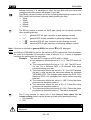
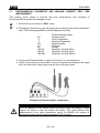
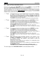
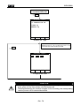
4. INSTRUMENT DESCRIPTION
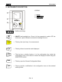
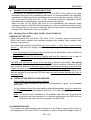
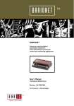
LEGEND:
1
1. Display
2. Function Keys
3. Rotary switch
2
F1
F2
F3
F4
3
START
STOP
F1 F2 F3 F4
ON/OFF
SAVE
HOLD
ENTER
MENU
ESC
Multifunction Keys.
ON/OFF and backlight key. Press it for few seconds to switch OFF the
instrument, press it briefly to activate the backlight function.
START
STOP
This key start (and stop). the measurement.
SAVE
This key allows to save the result displayed.
HOLD
ENTER
This key has a double function: it is the confirmation key inside the
configuration menu and it allows to freeze the displayed results using the
ANALYZER function.
MENU
This key open the General Configuration Menu.
ESC
This key quit the .modification in the configuration menu or the selected
working mode.
EN - 9
SIRIUS89N
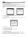
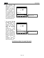
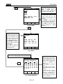
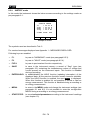
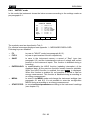
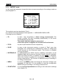
4.1.
DISPLAY DESCRIPTION
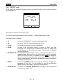
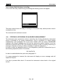
The display is a graphic module with a resolution of128 x 128 pixels.
The first line of the display shows date and time. If not correct, you can set the exact ones
according to the procedure described at paragraph 5.2.
On the top right corner of the display you can always see the battery indicator and, if the
external power supply adapter (optional code A0050) is connected, the corresponding
symbol.
LOWΩ
27.09.00
05.06.01
17:35:12
SINGLE PHASE
VOLTAGE
----Ω
R+
----Ω
---mA
V1
Vpk1
ThdV
freq
R----Ω
---mA
AUTO 0.11Ω
FUNC
CAL
HARM
=
=
=
=
230.2 V
325.5 V
0.0
%
50.0 Hz
WAVE
These symbols will be omitted in the following illustrations.
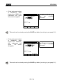
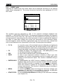
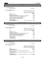
4.2.
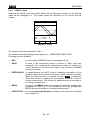
INITIAL SCREEN
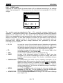
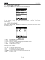
When turning on the instrument by pressing ON/OFF, this screen will appear for a few
seconds:
SIRIUS89N
HT ITALIA
SN:00000000 V: X.XX
BAUD RATE 57600
CALIBRATION DATE
01.01.02
Here you can see:
•
•
•
•
serial number of the instrument (SN.:)
firmware software release (V.X.XX:)
transmission speed through serial RS232 (Baud Rate)
calibration date (CALIBRATION:)
4.3.
BACKLIGHT FUNCTION
When instrument is turned on, pressing briefly the ON button, the backlight will be
enabled. The light will be automatically turned off after 5 seconds.
If the batteries are too low the instrument will disable automatically the backlight function.
EN - 10
SIRIUS89N
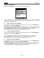
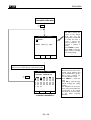
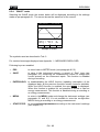
5. INITIAL SETTINGS
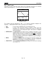
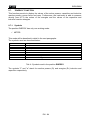
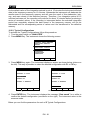
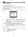
By pressing the MENU key the following screen will be displayed:
MENU GENERAL
SAFETY TEST MEMORY
ANALYZER MEMORY
RESET
ANALYZER CONFIG
RECORDER CONFIG
CONTRAST
DATE&TIME
LANGUAGE
↓
↑
It’s not possible to enter the MENU during a recording or a Real Time Energy
measurement. Pressing this button during a recording the display will show main recording
parameter (see paragraph 10.3).
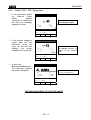
5.1.
HOW TO ADJUST THE CONTRAST
By pressing the multifunction keys F1 and F2, position the cursor on the CONTRAST item
and confirm it by pressing the ENTER key.
By pressing the multifunction keys F3 and F4, adjust the contrast (higher values
correspond to a higher contrast while lower values correspond to a lower contrast) and
press the ENTER key to SAVE the change or press ESC to quit the modification.
This setting will remain unchanged after turning off the instrument.
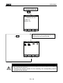
5.2.
HOW TO SET DATE AND TIME
By pressing the multifunction keys F1 and F2, position the cursor on the DATE&TIME item
and confirm it by pressing the ENTER key.
The time is expressed as hh:mm (2 digit for hours, 2 digit for minutes) military time.
Press the ENTER key to SAVE the change or press ESC to quit the modification.
This setting will remain unchanged also after turning off the instrument.
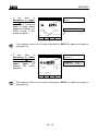
5.3.
HOW TO SET THE LANGUAGE
By pressing the multifunction keys F1 and F2, position the cursor on the LANGUAGE (EN)
or LINGUA (IT) item and confirm it by pressing the ENTER key.
By pressing the multifunction keys F1 and F2, position the cursor on the desired language
and press the ENTER key to SAVE the change or press ESC to quit the modification.
This setting will remain unchanged after turning off the instrument.
EN - 11
SIRIUS89N
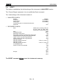
5.4.
RESET
This option re-establishes the initial settings of the instrument in ANALYZER function.
The “Current Range” parameter it is not modified by Reset command
The initial settings of the instrument consist of:
ANALYZER CONFIG:
System:
Frequency:
Current range:
Clamp type:
Transforming ratio of voltmetric transformers:
Password:
SINGLE
not modified
not modified
not modified
1
OFF
RECORDER CONFIG:
Start:
MANU (the recording starts at
00 sec mark on clock after
pressing the START/STOP key)
Stop:
MAN
Integration period:
15min
Recording of harmonics:
ON
Recording of Voltage anomalies (Sag and Surge:
ON
Voltage Reference for Sag and Surge detection:
230V
Upper Limit for Sag and Surge detection:
6%
Lower Limit for Sag and Surge detection:
10%
Selected voltages:
V1
Selected voltage harmonics:
THD, 01, 03, 05, 07
Selected currents:
I1
Selected current harmonics:
THD, 01, 03, 05, 07
CO-GENERATION:
OFF
Powers, Pf and cosϕ selected:
P1
Q1i
Q1c
S1
Pf1
DPf1
Energie:
Ea1
Eri1
Erc1
The RESET command will not erase the instrument’s memory.
EN - 12
SIRIUS89N
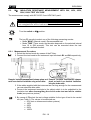
6. SAFETY TEST FUNCTIONS
6.1.
LOWΩ:
CONTINUITY TEST WITH 200mA TEST CURRENT
The measurement is effected according to EN 61557-2 and VDE 0413 part 4.
CAUTION
Before carrying out the continuity test make sure that there is no voltage at
the ends of the conductor under test.
Turn the switch on LOWΩ position.
This key permits to select one of the following measuring modes:
Mode "AUTO" (the instrument carries out two measurements with
reversed polarity and displays their average value). This mode is
recommended for the continuity test.
Mode "RT+" (measurement with positive polarity and possibility of setting
the duration time of the test). In this case the operator can set a
measuring time long enough to permit him to move the protective
conductors while the instrument is carrying out the test so detecting any
bad connection.
Mode "RT-" (measurement with negative polarity and possibility of setting
the duration time of the test). In this case the operator can set a
measuring time long enough to permit him to move the protective
conductors while the instrument is carrying out the test so detecting any
bad connection.
This key permits to execute the "CAL" mode (compensation of the resistance
of the cables used for the measurement).
CAUTION
If the resistance is lower than 5Ω (including the resistance of the calibration)
the continuity test is executed by the instrument with a test current higher
than 200mA. If the resistance is higher than 5Ω the continuity test is
executed by the instrument with a current lower than 200mA.
We recommend you to check the Calibration of the test leads before executing a
measurement according to next paragraph.
EN - 13
SIRIUS89N
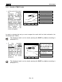
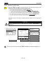
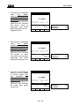
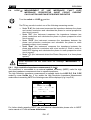
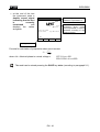
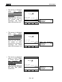
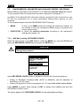
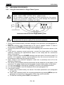
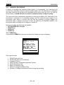
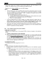
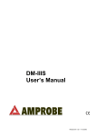
6.1.1. Calibrating the test leads ("CAL" Mode)
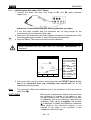
1. Connect the black and blue test leads to B1 and B4 input terminals
respectively.
Connection of instrument terminals during calibration procedure.
2. If the test leads supplied with the instrument are not long enough for the
measurement you can extend the blue cable.
3. Short-circuit the measuring cable ends making sure that the conductive parts of the
crocodiles make a good contact to each other (see previous picture).
4. Press the F2 key. The instrument carries out the calibration.
CAUTION
Never disconnect the test leads when the message "MEASURING" is
displayed.
LOWΩ
05.06.01
----Ω
R+
----Ω
---mA
AUTO 0.11Ω
FUNC CAL
R----Ω
---mA
A numerical value
in this field means
that the instrument
has
been
calibrated;
this
value remains on
the display for
any
further
measurement
even though the
unit is switched off
and on again
5. At the end of the test the result is stored and used as OFFSET (that is to say
that it is subtracted from any continuity test carried out) for all the
subsequent measurements.
Note:
The instrument effects the calibration only if the resistance of the test leads is
lower than 5Ω.
TEST LEADS
Before each measurement always make sure that
the calibration is referred to the cables in use.
During a continuity test, if the resistance value free
of calibration (that is the resistance value less the
calibration offset value) is negative, the symbols
o is displayed. Probably the calibration resistance
value stored in the instrument memory is not
referred to the cable in use, therefore a new
calibration must be effected.
EN - 14
SIRIUS89N
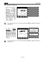
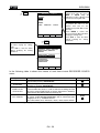
6.1.1.1.
Procedure to reset test leads calibration parameters
To cancel calibration
parameters
it
is
necessary to effect a
calibration procedure
with a resistance of
test leads higher than
5Ω (for example with
open test leads). When
a cancellation is effected
the screen nearby is
displayed first, followed
by the screen below:
LOWΩ
05.06.01
o>
Ω
R+
----Ω
---mA
AUTO
FUNC
R----Ω
---mA
Message
>99.9Ω:
means
that
the
instrument detected a
resistance
higher
than 5Ω therefore it
will proceed with
Reset procedure.
0.11Ω
CAL
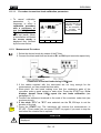
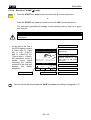
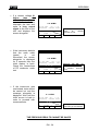
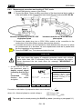
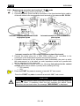
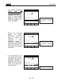
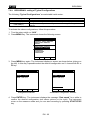
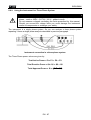
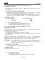
6.1.2. Measurement Procedure
1. Select the desired mode by means of the F1 key.
2. Connect the black and blue test leads to B1 and B4 input terminals respectively
Connection of the test leads during LOWΩ test.
START
STOP
3. If the cables supplied with the instrument are not long enough for the
measurement you can extend the blue cable.
4. Short-circuit the test leads making sure that the conductive parts of the
crocodiles make a good contact to each other. Press the START key. If the
displays doesn't show 0.00Ω repeat the test leads calibration (see
paragraph 6.1.1).
5. Connect the instrument terminals to the ends of the conductor under test (see
previous picture).
6. If the mode "RT+" or "RT-" was selected use the F3, F4 keys to set the
duration of the test.
7. Press the START key. The instrument will execute the measurement. In
RT+/RT- (Timer mode) you can press START key again if you want to stop the
test before the duration set is expired.
CAUTION
Never disconnect the test leads when the message "MEASURING" is
displayed.
EN - 15
SIRIUS89N
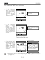
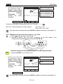
6.1.3. Results of "AUTO" mode
At the end of the test, if
the average resistance
value Ravg is lower
than 5Ω the instrument
emits a double sound
signal indicating the
positive outcome of
the test and displays
one screen similar to the
screen alongside.
LOWΩ
05.06.01
Average resistance value
(Ravg)
Ω
R+
1.07Ω
219mA
AUTO
FUNC
R1.03Ω
219mA
0.11Ω
Resistance values and
corresponding test current
got
exchanging
the
polarities of test leads
CAL
The displayed result can be stored pressing the SAVE key twice (according to
paragraph 9.1).
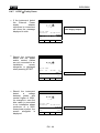
6.1.4. Results of "RT+" and "RT-" modes
if a resistance value
RT+ or RT+ lower than
5Ω is detected, the
instrument
emits
a
double sound signal
indicating the positive
outcome of the test
displays one screen
similar to the screen
alongside.
Note:
LOWΩ
05.06.01
Ω
Max Resistance value of
R+ or R-.
Test current
219mA
Duration of the Test
RT+
FUNC
0.11Ω TIME: 10s
CAL
↑
↓
We recommend to use crocodiles and to check if the crocodiles make a good
contact with the conductor under test. Indeed in this test the instrument gives as
final result the maximum measured value of R+ or R- and suing test leads
instead of crocodiles could give you faulty result due to faulty contact between
the test leads and conductor under test
The displayed result can be stored pressing the SAVE key twice (according to
paragraph 9.1).
EN - 16
SIRIUS89N
6.1.5. "AUTO", RT+", "RT-" faulty cases
If the instrument detect
the
External
Power
supply
adapter
connected to instrument
will show the message
displayed to side.
LOWΩ
05.06.01
Ω
R+
---Ω
---mA
Disconnect the External
Power Supply Adapter
R---Ω
---mA
o REMOVE POWER
AUTO
FUNC
If the terminal voltage is
higher than 15V, the
instrument does not
carry out the test and
displays
the
screen
alongside for 5 seconds.
0.11Ω!
CAL
LOWΩ
05.06.01
Ω
R+
-.--Ω
---mA
R-.--Ω
---mA
ATTENTION: the test was
not effected because of
voltage at the terminal
ends.
o VOLT IN INPUT
AUTO
FUNC
In case that:
RCALIBRATION>RMEASURED
the instrument displays
the screen alongside.
0.11Ω
CAL
LOWΩ
05.06.01
Ω
o
R+
0.00Ω
219mA
R0.00Ω
219mA
ATTENTION:
RCALIBRATION >RMEASURED
CAL > RES
AUTO
FUNC
0.11Ω
CAL
THE PREVIOUS RESULTS CAN'T BE SAVED.
EN - 17
SIRIUS89N
If
the
value
of
Resistance is higher
than 5Ω (but lower than
99.9Ω) the instrument
emits a long sound
signal and displays one
screen similar to the
screen alongside
LOWΩ
05.06.01
R+
5.17Ω
209mA
FUNC
value
higher
Ω
o
AUTO
Resistance
than 5Ω
R5.17Ω
209mA
Test current
0.11Ω
CAL
The displayed result can be stored pressing the SAVE key twice (according to
paragraph 9.1).
If
the
value
of
Resistance is higher
than
99.9Ω
the
instrument emits a long
sound
signal
and
displays the screen
alongside.
LOWΩ
05.06.01
Ω
o
R+
-.--Ω
---mA
AUTO
FUNC
Resistance
than 99.9Ω
value
higher
ATTENTION: Value of
Resistance Out of Range
R-.--Ω
---mA
0.11Ω
CAL
The displayed result can be stored pressing the SAVE key twice (according to
paragraph 9.1).
EN - 18
SIRIUS89N
6.2.
MΩ:
INSULATION RESISTANCE MEASUREMENT WITH 50V, 100V, 250V,
500V, 1000V TEST VOLTAGE
The measurement comply with IEC 61557-2 and VDE 0413 part 1.
CAUTION
Before effecting the insulation test make sure that the circuit under test is
not energised and all the loads are disconnected.
Turn the switch on MΩ position.
The key F1 permits to select one of the following measuring modes:
Mode "MAN" (Manual mode). Recommended test.
Mode "TMR" (Timer mode: test duration depends on the selected interval
from 10 to 999 seconds). This test can be executed when the test
required a defined duration.
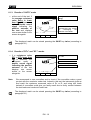
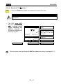
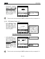
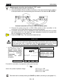
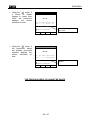
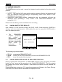
6.2.1. Measurement Procedure
1. Select the desired mode by means of the F1 key.
2. Connect the test leads to the instrument input terminals B1 and B4 respectively,
Example: insulation measurement between phase and Example: insulation measurement between
phase and earth in an electrical installation
earth in an electrical installation using untied cables.
using the shuko cable.
3. If the cables supplied with the instrument are not long enough for the measurement
you can extend the blue cable.
4. Connect the instrument terminals to the object which is to be submitted to the
insulation test after de-energizing the circuit under test and all the relative
loads (see previous picture).
5. By means of F2 select the test voltage suitable for the type of test to be carried
out (see Table1). The values to be selected are:
• 50V (test on telecommunication systems)
• 100V
• 250V
• 500V
• 1000V
EN - 19
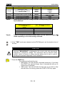
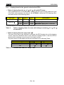
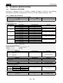
SIRIUS89N
Standard
CEI 64-8/6
CEI 64-8/4
EN60439
EN60204
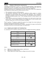
Table1:
Table2:
Brief description
Test voltage
Maximum limit value
Systems SELV or PELV
Systems up to 500V (Civil installations)
Systems over 500V
Floor and wall insulation in civil installations
Floor and wall insulation in systems over 500V
Electrical panel boards 230/400V
Electrical equipment of machines
250VDC
500VDC
1000VDC
500VDC
1000VDC
500VDC
500VDC
> 0.250MΩ
> 0.500MΩ
> 1.0MΩ
> 50kΩ (se V<500V)
> 100kΩ (se V>500V)
> 230kΩ
> 1MΩ
Table reporting the test voltage and the corresponding limit values for
few Guidelines.
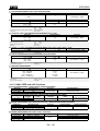
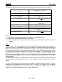
Rated voltage selected
for the test
RMAX = Maximum resistance
value
50VDC
100VDC
250VDC
500VDC
1000VDC
99.9MΩ
199.9MΩ
499MΩ
999MΩ
1999MΩ
Table of maximum resistance values which can be measured under MΩ
mode depending on the rated voltage selected.
6. If the "TMR" mode was selected use the F3, F4 keys to set the duration time of
the test:
CAUTION
Never disconnect the test leads from the circuit under test when the
message "MEASURING" is displayed as the circuit under test may remain
charged at a dangerous voltage. The instrument has an internal "safety
resistor" which is connect to output terminal before end of test in order to
discharge the parasite capacities of the installation
START
STOP
7. Press the START key.
The instrument will start the test.
MAN Mode: The test will take 4 seconds (maximum). If you keep
the START key pressed longer than 4 seconds the test go on
until the key is released.
TMR mode: The test will take the time set. If you want to stop
the test when it's running, press the START STOP key again.
EN - 20
SIRIUS89N
6.2.2. Results of "MAN" mode
At the end of the test if
the
Insulation
resistance is lower
than RMAX (see Table2)
and the instrument
generated
the
Nominal test Voltage,
the instrument emits a
double sound signal
indicating the positive
outcome of the test
and
displays
one
screen similar to the
screen alongside.
MΩ
05.06.01
Insulation Resistance
Voltage during the Test
MΩ
514V
15s
MAN
500V
FUNC
VNOM
Duration of the Test
Test mode
Test voltage set
In order to evaluate the test you must compare the result with the limits indicated in the
Guidelines (see Table1).
The displayed result can be stored pressing the SAVE key twice (according to
paragraph 9.1).
If
the
Insulation
resistance is higher
than RMAX (see Table2),
the instrument emits a
double sound signal at
the end of the test
indicating the positive
outcome of the test
and displays one screen
similar to the screen
alongside.
MΩ
05.06.01
MΩ
523V
MAN
FUNC
15s
500V
VNOM
Maximum resistance value
which can be measured
(999Ω is displayed if a
rated voltage of 500V was
selected see Table2).
The symbol ">" means that
the resistance value is
higher than RMAX .
Test duration
The displayed result can be stored pressing the SAVE key twice (according to
paragraph 9.1).
EN - 21
SIRIUS89N
6.2.3. Results of "TMR" mode
At the end of the test if
the
Insulation
resistance is lower
than RMAX (see Table2)
and the instrument
generated
the
Nominal test Voltage,
the instrument emits a
double sound signal
indicating the positive
outcome of the test
and
displays
one
screen similar to the
screen alongside.
MΩ
05.06.01
Insulation Resistance
MΩ
Voltage during the Test
514V
TMR
Test mode
15s
500V
FUNC
Duration of the Test
TIME:60s
VNOM
↑
Setting Time
↓
The displayed result can be stored pressing the SAVE key twice (according to
paragraph 9.1).
If
the
Insulation
resistance is higher
than RMAX (see Table2),
the instrument emits a
double sound signal at
the end of the test
indicating the positive
outcome of the test
and displays one screen
similar to the screen
alongside.
MΩ
05.06.01
MΩ
523V
15s
TMR 500V
TIME:60s
FUNC VNOM
↑
↓
Maximum resistance value
which can be measured
(999Ω is displayed if a
rated voltage of 500V was
selected see Table2).
The symbol ">" means that
the resistance value is
higher than RMAX .
Test duration
The displayed result can be stored pressing the SAVE key twice (according to
paragraph 9.1).
EN - 22
SIRIUS89N
6.2.4. "MAN" and "TIMER" mode faulty cases
If
the
instrument
detect the External
Power supply adapter
connected
to
instrument will show
the
message
displayed to side.
MΩ
05.06.01
MΩ
---V
Disconnect the External Power
Supply Adapter
15s
o REMOVE POWER
MAN
FUNC
If
the
instrument
detect
a
Voltage
between
Input
terminals higher than
15V, the instrument
does not effect the
test and displays the
screen alongside for 5
seconds.
500V!
VNOM
MΩ
05.06.01
MΩ
---V
ATTENTION: the test can't be
executed. Check that the circuit is
not energised.
15s
o VOLT IN INPUT
MAN
FUNC
500V
VNOM
These result can't be saved
If the instrument can't
generate the Nominal
Test Voltage it will
emits
a
long
acoustic signal and
displays a screen
similar to the screen
alongside.
MΩ
05.06.01
MΩ
o
107V
MAN
FUNC
15s
Insulation Resistance
ATTENTION:
the
test
of
resistance RISO was effected at
a voltage value lower than the
set
rated
voltage.
Low
insulation case. This case
occurs under low insulation
conditions or in the presence of
capacity on the installation.
500V
VNOM
Test Time
The displayed result can be stored pressing the SAVE key twice (according to
paragraph 9.1).
EN - 23
SIRIUS89N
6.3.
RCD:
TEST ON "A" AND "AC" RCDS TYPE
The test is executed according to IEC61557-6, EN61008, EN61009, EN60947-2 B 4.2.4
and VDE 0413 part 6.
CAUTION
The automatic check of the RCD features causes the tripping of the RCD itself.
Therefore check that all devices connected downstream the RCD under
test are not damaged by power off. Possibly disconnect all the loads
connected downstream the RCD as they could add additional leakage currents
to the instrument ones and so making the test results void.
Turn the switch on RCD position:
The F1 key permits to select one of the following measuring mode (which can
be shown cyclically when pressing the key):
Mode "AUTO" (the instrument effects the test automatically with a
leakage current equal to half, once and five times the value of the rated
current set). Recommended test.
Mode "x ½" (the instrument effects the test with a leakage current equal
to half the value of the rated current set).
Mode "x 1" (the instrument effects the test with a leakage current equal
to once the value of the rated current set ).
Mode "x 2" (the instrument effects the test with a leakage current equal
to twice the value of the rated current set).
Mode "x 5" (the instrument effects the test with a leakage current equal
to five times the value of the rated current)
Mode " " (the instrument effects the test with a ramp growing leakage
current. Use this test to measure the tripping current).
Mode "RA " (the instrument effects the test with a leakage current
equal to half the value of the selected rated current and calculates the
contact voltage as well as the Ra earth resistance).
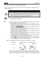
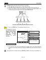
N.B. The AUTO mode execute automatically test with phase 0° and 180°
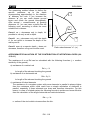
RCD Type
0° Current Waveform 180° Current Waveform
AC type
A type
According to standard praxis it is recommended to effect RCD test both with
phase 0° and with phase 180° even with no AUTO modes. If the RCD under
test is A type (which means sensitive to both AC and unidirectional pulsing
EN - 24
SIRIUS89N
leakage currents) it is advisable to effect the test both with sine wave and
unidirectional pulse current with phase 0° and 180°.
The F2 key permits to select one of the following rated tripping currents of the
RCD (which can be shown cyclically when pressing the key):
10mA.
30mA.
100mA.
300mA.
500mA.
The F3 key permits to select the RCD type (which can be shown cyclically
when pressing the key):
"b":
"l":
"bn":
"ln":
general RCD AC type (sensitive to sine leakage current)
general RCD A type (sensitive to pulsating leakage current)
selective RCD AC type (sensitive to sine leakage current)
selective RCD A type (sensitive to pulsating leakage current)
Note if the test is effected on general RCDs the symbol n is NOT displayed
Note according to EN61008 the test on the selective RCDs requires an interval between
the tests of 60 seconds (30 seconds in case of tests at ½ I ∆n). A timer is displayed
indicating the waiting time for each step.
Example:
Test with AUTO mode on a RCD with I∆n=30mA.
a) the instrument effects the test at ½ I ∆n 0°. The RCD must not
trip.
b) The instrument effects the test at ½ I ∆n 180°. The RCD must
not trip. For a Selective RCD a 30 seconds timer starts
before executing next test.
c) The instrument effects the test at I∆n 0°. If the RCD passed
the test, it must trip and the instrument shows the message
"RESUME RCD". The operator shall resume the RCD. For a
Selective RCD a 60 seconds timer starts before executing
next test.
d) The instrument effects the test at I∆n 180°. Follow the same
procedure as described under c).
e) The instrument effects the test at 5I∆n 0°. Follow the same
procedure as described under c).
f) The instrument effects the test at 5I∆n 180°. Follow the same
procedure as described under c). The test is completed.
The F4 key permits to select one of the following limit values for the
contact voltage (which can be shown cyclically when pressing the key):
50V (default)
25V.
CAUTION
Never disconnect the test leads when the message "MEASURING" is
displayed.
EN - 25
SIRIUS89N
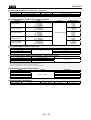
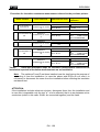
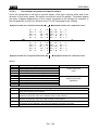
6.3.1. Tripping times for the general and selective RCDs
Table of tripping times for I∆N x1, I∆N x2, I∆N x5 and AUTO tests.
If the parameters set on the instrument comply with the type of RCD under test (and
if the latter works properly) the test x1, x2, x5 SHALL cause the RCD tripping within
the times shown in the following table:
RCD type
I∆N x 1
I∆N x 2
I∆N x 5
General
0.3s
0.15s
0.04s
Max tripping time in seconds
0.5s
0.20s
0.15s
Max tripping time in seconds
0.13s
0.05s
0.05s
Minimum tripping time in seconds
Selective S
Description
* For rated values I∆N ≤ 30mA the test current at five times is 0.25A.
For currents equal to ½ I∆N the RCD shall not trip in any case.
Table 3:
Table of tripping times for tests with leakage currents I∆N x1, I∆N x2, I∆N
x5 and AUTO.
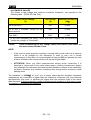
Table of tripping times for ramp tests " ".
This test is not used to be effected to compare the RCD tripping time at the tripping
current, while the standards refer to the maximum tripping times in case the RCD is
checked with a leakage current equal to the rated current.
The limits value for the tripping current are indicated in the following Table:
Table 4:
RCD Type
I∆N ≤ 10mA
I∆N > 10mA
A
1,4 x I∆N
1,4 x I∆N
AC
I∆N
I∆N
Current limit value for "Ramp" Test
EN - 26
SIRIUS89N
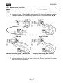
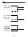
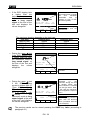
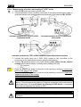
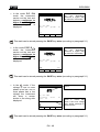
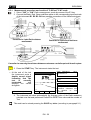
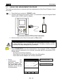
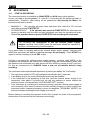
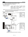
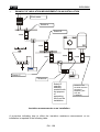
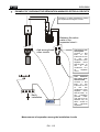
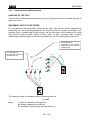
6.3.2. Measurement procedure
1. Select the desired test parameter by means of the F1, F2, F3, F4 key.
2. Connect the Black, Green and Blue connectors of the three-terminal shuko cable or
of the split cables to the corresponding input terminals of the instrument B1, B3, B4
Instrument connection for 400V + N + PE threephase RCD check
Instrument connection for 230V single-phase
RCD check
Instrument connection for 400V + N (no PE) threephase RCD check
Instrument connection for 400V + PE (no N)
three-phase RCD check
3. Connect the shuko plug or the Test leads to the System under test according
with one of the picture above.
EN - 27
SIRIUS89N
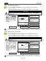
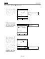
6.3.2.1. Results of "x½" mode
START
STOP
4. Press the START key once to execute a test with 0° Current waveform.
or
Press the START key once to execute a test with 180° Current waveform.
CAUTION
Never disconnect the test leads when the message "MEASURING" is
displayed.
If the RCD does NOT
trip the instrument emits
a double sound signal
indicating the positive
outcome of the test and
displays the screen
alongside.
RCD
05.06.01
The symbol ">" means that
the RCD did not trip.
ms
Value of contact voltage Ut
detected referred to the
rated value of the RCD
current set.
FRQ=50.0Hz Ut= 1V
VP-N=231V VP-PE=231V
RCD OK
x1/2
FUNC
Working mode
30mA
IdN
RCD
OK: RCD passed the test.
50V!
UL
RCD nominal current
Contact Voltage Limit value
RCD type
The test can be stored pressing the SAVE key twice (according to paragraph 9.1).
6.3.2.2. Results of "x1, x2, x5" mode
START
STOP
4. Press the START key once to execute a test with 0° Current waveform.
or
Press the START key once to execute a test with 180° Current waveform.
CAUTION
Never disconnect the test leads when the message "MEASURING" is
displayed.
If the tripping time is
within the limits reported
in
Table
3,
the
instrument
emits
a
double sound signal
indicating the positive
outcome of the test and
displays the screen
alongside.
RCD
ms
FRQ=50.0Hz Ut= 2V
VP-N=231V VP-PE=231V
RCD OK
x1
FUNC
Working mode
05.06.01
30mA
IdN
RCD
Tripping time (expressed in
milliseconds).
Value of contact voltage Ut
detected referred to the
rated value of the RCD
current set.
OK: RCD passed the test.
50V!
UL
RCD nominal current
Contact Voltage Limit value
RCD type
The test can be stored pressing the SAVE key twice (according to paragraph 9.1).
EN - 28
SIRIUS89N
6.3.2.3. Results of "AUTO" mode
START
STOP
4. Press the START key once to execute the test. The instrument carries out the
following six tests with different values of rated current:
1/2I∆n with 0° current waveform (the RCD shall not trip).
1/2I∆n with 180° current waveform (the RCD shall not trip).
I∆n with 0° current waveform (the RCD trips, message " RESUME RCD").
I∆n with 180° current waveform (the RCD trips, message " RESUME RCD").
5I∆n with 0° current waveform (the RCD trips, message " RESUME RCD").
5I∆n with 180° current waveform (the RCD trips, end of the test).
The test is good if all values of tripping times are within the limits reported in
Table 3.
CAUTION
Never disconnect the test leads when the message "MEASURING" is
displayed.
At the end of the test if
all six tests resulted to
be
positive,
the
instrument displays the
screen
alongside
relative to the last
measurement effected.
RCD
0°
x1/2 >999ms
05.06.01
180°
>999ms
Tripping time (expressed in
milliseconds).
Value of contact voltage Ut
detected referred to the
rated value of the RCD
current set.
x1
55ms
65ms
x5
20ms
30ms
FRQ=50.0Hz
VP-N=231V
Ut= 1V
VP-PE=231V
RCD OK
AUTO
FUNC
Working mode
30mA
IdN
RCD
OK: RCD passed the test.
50V!
UL
RCD nominal current
Contact Voltage Limit value
RCD type
The test can be stored pressing the SAVE key twice (according to paragraph 9.1).
EN - 29
SIRIUS89N
6.3.2.4. Results of "RAMP
START
STOP
" mode
4. Press the START key once to execute a test with 0° Current waveform.
or
Press the START key once to execute a test with 180° Current waveform.
The instrument generates a leakage current growing step by step for a given
time interval.
CAUTION
Never disconnect the test leads when the message "MEASURING" is
displayed.
At the end of the test if
the RCD tripping current
is lower than I∆n (Type
AC) or 1.4I∆n (Type A
with I∆n >10mA) or 2I∆n
(Type A with I∆n ≤10mA),
the instrument emits a
double sound signal
indicating the positive
outcome of the test and
displays the screen
alongside.
Working mode
Tripping Current
RCD
05.06.01
mA
35ms
FRQ=50.0Hz
VP-N=231V
Ut= 1V
VP-PE=231V
RCD OK
FUNC
30mA
IdN
RCD
Tripping time (expressed in
milliseconds).
Value of contact voltage Ut
detected referred to the
rated value of the RCD
current set.
OK: RCD passed the test.
50V!
UL
RCD nominal current
Contact Voltage Limit value
RCD type
The test can be stored pressing the SAVE key twice (according to paragraph 9.1).
EN - 30
SIRIUS89N
6.3.2.5. Results of " RA
START
STOP
" mode
4. Press the START key once: the instrument carries out the test.
CAUTION
Never disconnect the test leads when the message "MEASURING" is
displayed.
The RCD must NOT
trip and the instrument
emits a double sound
signal indicating the
positive outcome of
the test and displays the
screen alongside.
RCD
05.06.01
Ω
FRQ=50.0Hz
VP-N=231V
Ut= 1V
VP-PE=231V
FUNC
Working mode
30mA
IdN
RCD
Resistance
Value of contact voltage Ut
detected referred to the
rated value of the RCD
current set.
OK:Contact
Dangerous.
Ut OK
RA
Global Earth
Value).
Voltage
Not
50V!
UL
RCD nominal current
Contact Voltage Limit value
RCD type
The test can be stored pressing the SAVE key twice (according to paragraph 9.1).
EN - 31
SIRIUS89N
6.3.3. RCD Faulty cases
6.3.3.1. Connection troubles
If the instrument detect
the
External
Power
supply
adapter
connected to instrument
will show the message
displayed to side.
RCD
05.06.01
ms
FRQ=50.0Hz
VP-N=230V
Disconnect the External
Power Supply Adapter
Ut= ---V
Vp-PE=230V
o REMOVE POWER
x1
FUNC
Should the instrument
detect that the phase
and/or neutral cables
are not connected to an
installation,
screen
alongside is displayed
when pressing START.
RCD
50V!
UL
05.06.01
ms
FRQ=50.0Hz
VP-N= 0V
Ut= ---V
Vp-PE= 0V
o LOW VOLTAGE
x1
FUNC
Should the instrument
detect
a
voltage
between phase and
neutral higher of 250V,
for example in case the
blue cable is connected
to an installation phase
conductor of a 400V
three-phase system, the
screen alongside is
displayed.
30mA
IdN
RCD
RCD
30mA
IdN
RCD
NO VOLTAGE Detected
50V!
UL
05.06.01
ms
FRQ=50.0Hz
Ut= ---V
VP-N=401V VP-PE= 230V
o HIGH VOLTAGE
x1
FUNC
30mA
IdN
RCD
EN - 32
50V!
UL
HIGH VOLTAGE Detected
SIRIUS89N
This screen is displayed
when
the
phase
conductor has been
exchanged with the
neutral one.
The instrument does not
effect the test. Reverse
the shuko plug or
exchange the black
cable with the blue one.
Repeat the test
RCD
This screen is displayed
when
the
phase
conductor has been
exchanged with the
Protection Conductors.
The instrument does not
effect the test. Reverse
the phase to earth
connection in the plug or
exchange the black
cable with the green one
RCD
This screen is displayed
when in a 230V Phase
to Phase System the
blue conductor was
reversed with respect to
the green one.
The instrument does not
effect the test. Reverse
the blue and green
conductors.
RCD
05.06.01
ms
FRQ=50.0Hz
Ut= ---V
VP-N=231V VP-PE=
0V
o CHANGE P-N
x1
FUNC
30mA
50V!
IdN
RCD
UL
Phase
and
Conductors
exchanged.
Neutral
are
05.06.01
ms
FRQ=50.0Hz
Ut= ---V
VP-N= 2V VP-PE= 230V
o CHANGE P-PE
x1
FUNC
30mA
50V!
IdN
RCD
UL
Phase and
Conductors
exchanged.
Protection
are
Neutral and
Conductors
exchanged.
Protection
are
05.06.01
ms
FRQ=50.0Hz
Ut= ---V
VP-N=130V VP-PE= 227V
o CHANGE N-PE
x1
FUNC
30mA
50V!
IdN
RCD
UL
EN - 33
SIRIUS89N
If a contact voltage Ut
higher
than
the
selected limit (UL) is
detected, the instrument
interrupts the test and
emits a long sound
signal at the end of the
test and displays the
screen alongside.
RCD
If the instrument detects
that the earth cable
(green)
is
not
connected, the screen
alongside is displayed
for 5 seconds then the
initial display is back.
Check the connections
of PE conductor under
test.
RCD
If the instrument gets
overheated, tests cannot
be carried out and the
message alongside is
displayed. Wait until the
initial screen is back in
order to proceed with
measurements.
RCD
05.06.01
ms
FRQ=50.0Hz
Ut= ---V
VP-N=234V VP-PE= 234V
o UT DANGEROUS
x1
FUNC
30mA
IdN
RCD
50V!
UL
The instrument
detect
an
protection circuit.
doesn't
efficient
05.06.01
ms
FRQ =50.0Hz
Ut= ---V
VP-N=234V VP-PE= 34V
o NO PE
x1
FUNC
30mA
50V!
IdN
RCD
UL
Message “NO PE”: the
instrument doesn't detect
an
efficient
protection
circuit.
05.06.01
ms
FRQ=50.0Hz Ut= ---V
VP-N=231V VP-PE= 230V
o HOT
x1
FUNC
500mA
IdN
RCD
50V!
UL
Message
“hot”:
the
instrument got overheated.
THE PREVIOUS RESULTS CANNOT BE SAVED.
EN - 34
SIRIUS89N
Using the RA function,
if a contact voltage Ut
higher
than
the
selected limit (UL) is
detected the instrument
emits a long sound
signal at the end of the
test and displays the
screen alongside.
RCD
05.06.01
Ω
FRQ=50.0Hz
Ut= 54V
VP-N=234V VP-PE= 34V
o UT NOT OK
RA
30mA
50V!
IdN
RCD
UL
FUNC
The instrument
detect
an
protection circuit.
doesn't
efficient
The test can be stored pressing the SAVE key twice (according to paragraph 9.1).
6.3.3.2.
RCD tripping "faulty cases"
If the RCD trips during
the
preliminary
test
performed before the
test (independently from
the working mode) the
instrument displays the
screen alongside.
RCD
05.06.01
ms
FRQ=50.0Hz Ut= ---V
VP-N=231V VP-PE= 230V
o RCD TRIPS
30mA
IdN
RCD
x1
FUNC
50V!
UL
The RCD trips too early.
Check if the RCD Nominal
Current is correct.
Some leakage currents
may be present in the
installation. Disconnect all
the
loads
connected
downstream the RCD.
THE PREVIOUS RESULTS CAN'T BE SAVED.
In the tests MAN x1, x2,
x5 and AUTO (during x1
and x5 tests), if the RCD
trips to separate the
circuit within a time not
complying with the limits
reported in Table 3, the
instrument emits a long
acoustic signal at the
end of the test and
displays
the
values
alongside.
RCD
05.06.01
o
RCD tripping time.
ms
FRQ=50.0Hz Ut=
1V
VP-N=231V VP-PE= 230V
o TIME NOT OK
x1
FUNC
30mA
50V!
IdN
RCD
UL
ATTENTION: the tripping
time is higher than the
standard limit.
The test can be stored pressing the SAVE key twice (according to paragraph 9.1).
EN - 35
SIRIUS89N
If the RCD tripping time
is higher than the
instrument’s measuring
limits, the instrument
emits a long sound
signal at the end of the
test and displays the
values alongside.
RCD
05.06.01
o
ms
FRQ=50.0Hz Ut=
1V
VP-N=231V VP-PE= 230V
o TIME NOT OK
x1
FUNC
30mA
IdN
RCD
50V!
UL
The maximum duration depends on the test type:
Test type
General RCD
MAN x1 test
999ms
MAN x2 test
200ms
MAN x5 test
50ms
" " test
300ms
test
During the ramp
if the RCD tripping time
is higher than the limit,
the instrument emits a
long sound signal at
the end of the test and
displays
the
values
alongside.
RCD
05.06.01
ATTENTION: the tripping
time is higher than the
standard limit.
Selective RCD
999ms
250ms
160ms
Tripping Current.
mA
>300ms
Freq=50.0Hz
Ut=
1V
VP-N=231V
Vp-PE=230V
o TIME NOT OK
FUNC
test
During the ramp
if the RCD tripping
current is higher than I∆n
(Type AC) or 1.4 I∆n
(Type A with I∆n>10mA)
or 2 I∆n (Type A with
I∆n≤10mA)
,
the
instrument emits a long
sound signal at the end
of the test and displays
the values alongside.
RCD tripping time is bigger
than
the
maximum
measurable
time
(it
depends on type of test,
see following table).
30mA
IdN
RCD
RCD
50V!
UL
05.06.01
o
mA
>300ms
FRQ=50.0Hz
VP-N=231V
Ut=
1V
VP-PE=230V
o CURRENT NOT OK
FUNC
30mA
IdN
RCD
50V!
UL
Tripping Time exceeding
limit value
Maximum
current
generated
by
the
instrument during the test
for general RCDs (the
value indicated is referred
to an AC type 30mA RCD,
in this case the maximum
current supplied is equal to
1.4xI∆N
ATTENTION:
the RCD tripping current is
higher than the Nominal
Value (I∆N=30mA was set
in the example).
The previous results can be stored pressing the SAVE key twice (according to
paragraph 9.1).
EN - 36
SIRIUS89N
6.4.
LOOP
: MEASUREMENT OF LINE IMPEDANCE, FAULT LOOP
IMPEDANCE, PROSPECTIVE SHORT CIRCUIT CURRENT
CALCULATION AND PHASE SEQUENCE INDICATOR
Turn the switch on LOOP
position.
The F1 key permits to select one of the following measuring modes:
Mode "P-N" (the instrument measures the impedance between the phase
and neutral conductors and calculates the phase to neutral prospective
short circuit current).
Mode "P-P" (the instrument measures the impedance between two
phase conductors and calculates the phase to phase prospective short
circuit current).
Mode "P-PE" (the instrument measures the impedance between the
phase and protective conductors and calculates the phase to earth
prospective short circuit current).
Mode "RA" (the instrument measures the impedance between the
phase and protective conductors with a test current of 15mA in order to
avoid RCD tripping and calculates the phase to earth prospective short
circuit current).
Mode " " (the instrument detect the Phase Sequence in a three-phase
system).
CAUTION
Never disconnect the test leads when the message "MEASURING" is
displayed.
6.4.1. High resolution Impedance measurement (0.1mΩ)
The instrument is connectable to an external optional accessory (IMP57) useful for high
resolution impedance measurement close to a power transformer.
The high Resolution impedance measurement is available inside the LOOP P-P, P-N, P-PE
modes by mean Un/I n key. If You enable the High Resolution Impedance Measurement
mode without connecting IMP57 the following screen will be displayed (e.g: Loop P-N):
LOOP
29.01.04
Z=-----Ω
R=-----Ω
V1-2=
IkSTD=----A
0V FRQ=
0.0Hz
NO
P-N
FUNZ
X=-----Ω
Z2Ω
ZSTD
IMP57
ICAL
RMT
For further details regarding IMP57 use and technical characteristics please refer to IMP57
user's manual or HT web site www. htitalia.com.
EN - 37
SIRIUS89N
6.4.2. Measurement procedure and results of "P-N" mode
1. Select P-N mode by means of the F1 key.
2. Connect the Black, Green and Blue connectors of the three-terminal shuko cable or
of the split cables to the corresponding input terminals of the instrument B1, B3, B4
Instrument connection for P-N in a 400V threephase system
Instrument connection for P-N test in a 230V
single-phase System
START
STOP
3. Connect the shuko plug into a 230V 50Hz socket or the crocodiles to the
conductors of the three-phase system (see previous pictures).
4. If possible disconnect all low impedance loads downstream the point at which
the measurement is to be taken, as such impedances would be in parallel with
the line impedance to be measured.
5. Press the START key. The instrument starts the test.
CAUTION
The measurement in a 230V System make flow a test current of 6A approx.
This may cause the tripping of magnetic protection switch with nominal
value lower than 10A. If necessary effect the test upstream the switch.
Never disconnect the test leads when the message "MEASURING" is
displayed.
At the end of the test
the instrument emits a
double sound signal
indicating that the test
is
correctly
terminated
and
displays the values
alongside.
LOOP
05.06.01
Ω
215A
FRQ=50.0HZ
VP-N=231V
VP-PE=231V
Value of phase to neutral line
impedance expressed in Ω.
Value of the phase to neutral
prospective
short
circuit
current expressed in Ampere
calculated according to the
following formula.
P-N!
Working mode
FUNC
Z2Ω
UN
Z PN
127 if Vmeas≤150
230 if 150V< Vmeas≤250
Formula for calculation of prospective short circuit current: I CC =
where UN = Nominal phase to neutral voltage =
This result can be stored pressing the SAVE key twice (according to paragraph 9.1).
EN - 38
SIRIUS89N
6.4.3. Measurement procedure and results of "P-P" mode
1. Select P-P mode by means of the F1 key.
2. Connect the Black, Green and Blue connectors of the three-terminal shuko cable or
of the split cables to the corresponding input terminals of the instrument B1, B3, B4
Instrument connection for P-P test in a 400V three-phase system
START
STOP
3. Connect the shuko plug into a 230V 50Hz socket or the crocodiles to the
conductors of the three-phase system (see previous pictures).
4. If possible disconnect all low impedance loads downstream the point at which
the measurement is to be taken, as such impedance would be in parallel with
the line impedance to be measured.
5. Press the START key. The instrument starts the test.
CAUTION
The P-P measurement in a 400V system make flow a test current of 11.5A
approx. This may cause the tripping of magnetic protection switch with nominal
value lower than 10A. If necessary effect the test upstream the switch. Never
disconnect the test leads when the message "MEASURING" is displayed.
At the end of the test
the instrument emits a
double sound signal
indicating that the test
is
correctly
terminated
and
displays the values
alongside.
Working mode
LOOP
05.06.01
Ω
701A
FRQ=50.0HZ
VP-P=402V
VP-PE=231V
Value of phase to phase
impedance expressed in Ω.
Value of the phase to phase
prospective
short
circuit
current expressed in Ampere
calculated according to the
following formula.
P-P!
FUNC Z2Ω
Formula for calculation of prospective short circuit current:
U
I CC = N
Z PP
127 if Vmeas≤ 150
where UN= phase to phase voltage
230 if 150V< Vmeas≤260
400 if Vmeas> 260
This result can be stored pressing the SAVE key twice (according to paragraph 9.1).
EN - 39
SIRIUS89N
6.4.4. Measurement procedure and results of "P-PE" mode
1. Select P-PE mode by means of the F1 key.
2. Connect the Black, Green and Blue connectors of the three-terminal shuko cable or
of the split cables to the corresponding input terminals of the instrument B1, B3, B4.
Instrument connection for P-PE test in a 230V
single-phase System
Instrument connection for P-PE in a 400V threephase system
Instrument connection for P-PE in a 400V three-phase system without Neutral conductor
START
STOP
3. Connect the shuko plug into a 230V 50Hz socket or the crocodiles to the
conductors of the three-phase system (see previous pictures).
4. The key F4 permits to select one of the following limit values for the contact
voltage (which can be shown cyclically when pressing the key):
50V (default).
25V.
5. Press the START key once to execute a test injecting a current in phase with
positive half wave of the voltage.
Press the START key twice to execute a test injecting a current in phase with
negative half wave of the voltage.
CAUTION
The P-PE measurement in a 230V System make flow a test current of 6A
approx. This may cause the tripping of magnetic protection switch with nominal
value lower than 10A and will cause the tripping of RCD device. If necessary
effect the test upstream the switch or RCD.
CAUTION
Never disconnect the test leads when the message "MEASURING" is
displayed.
EN - 40
SIRIUS89N
At the end of the test
the instrument emits a
double sound signal
indicating that the test
is
correctly
terminated
and
displays the values
alongside.
LOOP
05.06.01
Ω
215A
Freq=50.0HZ
VP-N=231V
Vp-PE=231V
Value of phase to Earth
Resistance expressed in Ω.
Value of the phase to Earth
prospective
short
circuit
current expressed in Ampere
calculated according to the
following formula.
P-PE!
FUNC Z2Ω
Working mode
Formula for calculation of prospective short circuit current:
U
I CC = N
Z PE
where UN = Nominal phase to neutral voltage =
127 if Vmeas≤150
230 if 150V< Vmeas≤250
This result can be stored pressing the SAVE key twice (according to paragraph 9.1).
EN - 41
SIRIUS89N
6.4.5. Measurement procedure and results of " RA " mode
1. Select RA mode by means of the F1 key.
2. Connect the Black, Green and Blue connectors of the three-terminal shuko cable or
of the split cables to the corresponding input terminals of the instrument B1, B3, B4.
Instrument connection for P-PE test in a 230V
single-phase System
START
STOP
Instrument connection for P-PE in a 400V threephase system
Instrument connection for P-PE in a 400V three-phase system without neutral
3. Connect the shuko plug into a 230V 50Hz socket or the crocodiles to the
conductors of the three-phase system (see previous pictures).
4. If possible disconnect all low impedance loads downstream the point at which
the measurement is to be taken, as such impedance would be in parallel with
the line impedance to be measured.
5. The key F4 permits to select one of the following limit values for the contact
voltage (which can be shown cyclically when pressing the key):
50V (default)
25V.
6. Press the START key once to execute a test with “0°” test current.
or
Press the START key twice to execute a test with “180°” test current.
CAUTION
The RA measurement make flow a test current of 15mA. This may cause the
tripping of 10mA. If necessary effect the test upstream the switch. Never
disconnect the test leads when the message "MEASURING" is displayed.
EN - 42
SIRIUS89N
At the end of the test
the instrument emits a
double sound signal
indicating that the test
is
correctly
terminated
and
displays the values
alongside.
LOOP
Ω
115A
Freq=50.0HZ
VP-N=231V
Vp-PE=231V
RA
Working mode
05.06.01
Value of phase to Earth
Resistance expressed in Ω.
Effective value of the phase
to Earth prospective short
circuit current expressed in
Ampere calculated according
to the following formula..
!
FUNC
UN
Z PE
127 if Vmeas≤150
230 if 150V< Vmeas≤250
Formula for calculation of prospective short circuit current:
where UN = Nominal phase to neutral voltage =
I CC =
This result can be stored pressing the SAVE key twice (according to paragraph 9.1).
6.4.6. Measurement procedure and results of " " mode
1. Select
mode by means of the F1 key.
2. Connect the Black, Red and Green connectors of the split cables to the
corresponding input terminals of the instrument B1, B2, B3.
Instrument connection for Phase Sequence Detection in a 400V three-phase system
START
STOP
3. Press the START key to execute a test.
At the end of the test
the instrument emits a
double sound signal
indicating that the test
is
correctly
terminated
and
displays the values
alongside.
LOOP
05.06.01
Phase Sequence OK
Value of the Phase to Phase
Voltage
FRQ=50.0HZ
VS-T=401V
VR-S=391V
VT-R=399V
OK
!
FUNC
Working mode
This result can be stored pressing the SAVE key twice (according to paragraph 9.1).
EN - 43
SIRIUS89N
6.4.7. LOOP
Faulty Cases
If the instrument detect
the
External
Power
supply
adapter
connected to instrument
will show the message
displayed to side.
LOOP
05.06.01
Ω
---A
FRQ=50.0HZ
VP-N=231V
Disconnect the External
Power Supply Adapter
VP-PE=230V
o REMOVE POWER
P-N!
FUNC Z2Ω
Should the instrument
detect that the phase
and/or neutral cables
are not connected to an
installation,
screen
alongside is displayed
when pressing START.
LOOP
05.06.01
Ω
---A
FRQ=50.0HZ
VP-N= 1V
VP-PE=
0V
NO VOLTAGE Detected
NO VOLTAGE
P-PE
FUNC
Should the instrument
detect
a
voltage
between phase and
neutral higher of 250V,
for example in case the
blue cable is connected
to an installation phase
conductor of a 400V
three-phase system, the
screen alongside is
displayed.
50V!
UL
Z2Ω
LOOP
05.06.01
Ω
---A
Freq=50.0HZ
VP-N=401V
VP-PE=230V
HIGH VOLTAGE Detected
HIGH VOLTAGE
P-PE
FUNC
Z2Ω
EN - 44
50V!
UL
SIRIUS89N
This screen is displayed
when
the
phase
conductor has been
exchanged with the
neutral one.
The instrument does not
effect the test. Reverse
the schuko plug or
exchange the black
cable with the blue one.
This screen is displayed
when
the
phase
conductor has been
exchanged with the
Protection Conductors.
The instrument does not
effect the test. Reverse
the phase to earth
connection in the plug or
exchange the black
cable with the green one
This screen is displayed
when in a 230V Phase
to Phase System the
blue conductor was
reversed with respect to
the green one.
The instrument does not
effect the test. Reverse
the blue and green
conductors.
LOOP
05.06.01
Ω
---A
FRQ=50.0HZ
VP-N=231V
VP-PE=
0V
CHANGE P-N
P-PE
FUNC
50V!
UL
Z2Ω
LOOP
Phase
and
Conductors
exchanged.
Neutral
are
05.06.01
Ω
---A
FRQ=50.0HZ
VP-N= 1V VP-PE= 230V
CHANGE P-PE
P-N!
FUNC Z2Ω
LOOP
Phase and
Conductors
exchanged.
Protection
are
Neutral and
Conductors
exchanged.
Protection
are
05.06.01
Ω
---A
FRQ=50.0HZ
VP-N=131V VP-PE= 227V
CHANGE N-PE
P-N!
FUNC Z2Ω
EN - 45
SIRIUS89N
If a contact voltage Ut
higher
than
the
selected limit (UL) is
detected the instrument
interrupts the test and
emits a long sound
signal at the end of the
test and displays the
screen alongside.
LOOP
05.06.01
Ω
---A
FRQ=50.0HZ
VP-N= 1V
Vp-PE=
Ut DANGEROUS
RA
FUNC
Should the instrument
detect
an
Earth
Resistance
extremely
high to consider no
presence
of
PE
conductor
or
Earth
installation
ones,
it
shows the message on
the right picture. Please
check the efficiency of
PE conductor and Earth
installation.
If the instrument gets
overheated, tests cannot
be carried out and the
message alongside is
displayed. Wait until the
initial screen is back in
order to proceed with
measurements.
0V
50V!
UL
LOOP
Message
“Ut”:
the
instrument doesn't detect
an
efficient
protection
circuit.
05.06.01
Ω
---A
FRQ=50.0HZ
VP-N=231V
Vp-PE= 40V
NO PE
P-PE
FUNC
50V!
UL
Z2Ω
LOOP
Message “NO PE”: the
instrument doesn't detect
an
efficient
protection
circuit.
05.06.01
Ω
---A
FRQ=50.0HZ
VP-N=231V
Vp-PE= 40V
o HOT o
P-P!
FUNC Z2Ω
EN - 46
Message
“hot”:
the
instrument got overheated.
SIRIUS89N
Using the " " mode, if
a Phase to Phase
voltage is lowert than
100V, the instrument
displays the screen
indicated on side.
LOOP
05.06.01
FRQ =50.0HZ VR-S=391V
VS-T= 0 V VT-R= 0V
o LOW VOLTAGE T
PHASE ROTATION!
Phase "T2 Voltage is lower
than 100V
FUNC
Using the " " mode, if
the instrument detect
two phases connected
together displays the
screen indicated on
side.
LOOP
05.06.01
FRQ =50.0HZ
VS-T= 0 V
VR-S=407V
VT-R=407V
o PHASE DOUBLED
PHASE ROTATION!
FUNC
Two phases are connected
together.
THE PREVIOUS RESULTS CANNOT BE SAVED.
EN - 47
SIRIUS89N
In the mode P-P, P-N
mode the instrument
carries out the test and
detects a resistance to
higher than 199.9Ω, the
screen alongside is
displayed.
LOOP
05.06.01
Ω
Message ">199.9" means
that
the
Resistance
measured is higher than
the maximum measurable
---A
FRQ =50.0HZ
VP-N= 1V
Vp-PE=
0V
P-N!
FUNC Z2Ω
This result can be stored pressing the SAVE key twice (according to paragraph 9.1).
In the mode P-PE, RA
mode the instrument
carries out the test and
detects a resistance to
higher than 1999Ω, the
screen alongside is
displayed.
LOOP
05.06.01
Ω
Message ">1999" means
that
the
Resistance
measured is higher than
the maximum measurable
---A
FRQ =50.0HZ
VP-N= 1V
Vp-PE=
RA
FUNC
0V
50V!
UL
This result can be stored pressing the SAVE key twice (according to paragraph 9.1).
In the
mode, if the
voltage of one or more
phase is too low, one or
more phase has a low
voltage the instrument
will show a screen
similar to the along side
displayed.
LOOP
05.06.01
FRQ =50.0HZ
VR-S=391V
VS-T=
VT-R= 0V
NOT CORRECT
!
FUNC
0V
Phase
correct
Sequence
not
Message “LOW Voltage
Phase T”: means that
Phase T has a low voltage
value. Similar message for
Phase R and S.
This result can be stored pressing the SAVE key twice (according to paragraph 9.1).
EN - 48
SIRIUS89N
6.5.
EARTH:
SOIL RESISTANCE AND RESISTIVITY MEASUREMENTS
Turn the switch on EARTH position.
The F1 key permits to select one of the following measuring modes (which
can be shown cyclically when pressing the key):
Mode "2-W" (the instrument measures the resistance between 2 points).
Mode "3-W" (the instrument measures the resistance using two auxiliary
earth rods).
Mode "ρ" (the instrument measures the ground resistivity).
At the end of each test, instrument shows automatically the medium value of Earth
Resistance or Earth Resistivity calculated on the base of any measured values until that
moment.
F2 key clear medium value of Earth Resistance or Earth Resistivity and the
counter of executed Resistance measures.
CAUTION
Never disconnect the test leads from the circuit under test when the
message "MEASURING" is displayed
EN - 49
SIRIUS89N
6.5.1. Measurement procedure and results of "2-W"and "3-W" mode
1. Select "2-W" or "3-W" Earth measurement mode by means of the F1 key.
2. Connect the Black, Red, Green and Blue cables to the corresponding input terminals
of the instrument B1, B2, B3, B4 (see possible connections in the following pictures).
Connection for 3 point Earth resistance
measurement
Connection for 2 point Earth Resistance
measurement
Connection for measuring the resistance between an extraneous conductive part and the earth system
START
STOP
3. Press the START key. The instrument starts the test.
At the end of the test
the instrument emits a
double sound signal
indicating that the
test
is
correctly
terminated
and
displays the values
alongside.
"3 Point" Working mode
EARTH
05.06.01
Ω
Vd= 1V
Test:04
RAVG=0.74Ω
Earth Resistance
expressed in Ω.
value
Voltage value of electrical
noise
Number of Test
Average Value of Earth
Resistance calculated over
the
Number
of
Test
displayed.
3-W!
FUNC CLR
4. The instrument will show automatically the Average value of the Earth resistance
calculate over the tests performed. Press F2 to RESET this value and the number of
Test.
This result can be stored pressing the SAVE key twice (according to paragraph 9.1).
EN - 50
SIRIUS89N
6.5.2. Measurement procedure and results of "ρ" mode
1. Select ρ measurement mode by means of the F1 key.
2. Select the distance d between the earth rods by means the F3 and F4 keys.
3. Connect the 4 Black, Red, Green and Blue connectors of the single cables in the
corresponding input terminals of the instrument B1, B2, B3, B4.
Instrument connection for Earth resistivity measurement
START
STOP
4. Press the START key. The instrument starts the test.
At the end of the test
the instrument emits a
double sound signal
indicating that the
test
is
correctly
terminated
and
displays the values
alongside.
EARTH
05.06.01
Ωm
Vd= 1V
CLR
value
Voltage value of electrical
noise
Number of Test
Test:04
ρAVG=0.74Ω
ρ
FUNC
Earth
Resistivity
expressed in Ωm.
DIST= 2m!
↑
↓
Average Value of Earth
Resistivity calculated over the
Number of Test displayed.
"ρ" Working mode
5. The instrument will show automatically the Average value of the Earth Resistivity
calculate over the tests performed. Press F2 to RESET this value and the number of
Test.
This result can be stored pressing the SAVE key twice (according to paragraph 9.1).
EN - 51
SIRIUS89N
6.5.3. "2-W", "3-W" and "ρ" faulty cases
If the instrument detect
the
External
Power
supply
adapter
connected to instrument
will show the message
displayed to side.
EARTH
05.06.01
Ω
Disconnect the External
Power Supply Adapter
Vd= ---V
Test:04
RAVG=0.74Ω
o REMOVE POWER
3-W!
FUNC CLR
If the Instrument detect
a voltage values higher
than 5V the instrument
will shows the screen
displayed alongside.
EARTH
o
05.06.01
Warning symbol:
noise in input.
Voltage
Message
"Rc":
Auxiliary Earth rods.
Check
Ω
Vd= 230V
Test:04
RAVG=0.74Ω
o VOLT IN INPUT
3-W!
FUNC CLR
The
message
"Rc
high" indicates that the
instrument can't flow
the minimum current
necessary
for
measurement. Check
that the terminals are
correctly
connected
and the Auxiliary earth
rod connected to B4
(blue conductor) has
not been inserted in a
pebbly
or
poor
conductive ground. If
necessary pour some
water around the rod.
EARTH
05.06.01
Ω
Vd= 1V
Test:04
RAVG=0.74Ω
o Rc HIGH
3-W!
FUNC CLR
EN - 52
SIRIUS89N
The
message
"Rp
high" indicates that the
instrument
can't
measure correctly the
Voltage from Auxiliary
Earth rod. Check that
the
terminals
are
correctly connected and
the Auxiliary earth rod
connected to B2 (red
conductor) has not been
inserted in a pebbly or
poor conductive ground.
If necessary pour some
water around the rod.
The message "Rp and
Rc high" indicates that
the instrument can't
measure correctly the
Voltage from Auxiliary
Earth rod and can't
flowe the minimum
current
for
measurement.
Check
that the terminals are
correctly connected.
Check if the Auxiliary
earth rod connected to
B2 (red conductor) and
B4(blue conductor) has
not been inserted in a
pebbly
or
poor
conductive ground. If
necessary pour some
water around the rod.
EARTH
05.06.01
Ω
Vd= 1V
Test:04
RAVG=0.74Ω
o Rp HIGH
3-W!
FUNC CLR
EARTH
Message
"Rp":
Auxiliary Earth rods.
Check
05.06.01
Ω
Vd= 1V
Test:04
RAVG=0.74Ω
o Rp and Rc HIGH
3-W!
FUNC CLR
Message "Rp and Rc HIGH":
Check Auxiliary Earth rods.
THE PREVIOUS RESULTS CANNOT BE SAVED.
EN - 53
SIRIUS89N
If the Instrument detect
a Resistance value
higher than 1999Ω, the
instrument will show
the screen alongside.
EARTH
05.06.01
Ω
Message ">1999" means that
the resistance value is higher
than
the
maximum
measurable.
Vd= 1V
Test:04
RAVG=0.74Ω
3-W!
FUNC CLR
This result can be stored pressing the SAVE key twice (according to paragraph 9.1).
If the Instrument detect
a
Resistivity
value
higher than 1999kΩm,
the
instrument
will
show
the screen
alongside.
EARTH
05.06.01
kΩm
Message ">1999" means that
the resistivity value is higher
than
the
maximum
measurable.
Vd= 1V
Test:04
ρAVG=0.74kΩm
ρ
FUNC
CLR
DIST=5m!
↑
↓
This result can be stored pressing the SAVE key twice (according to paragraph 9.1).
EN - 54
SIRIUS89N
7. AUX: MEASUREMENT WITH EXTERNAL PROBES
Turn the switch on AUX position.
The F4 function key assume the following operations:
Pressing this key the instrument shows one of the following working
mode displayed circularly:
Environmental Parameter & Leakage Current (mA, °C, °F, HR%, m/s, mV, Lux)
Sound Level Measurement
The "Environmental Parameter & Leakage Current" mode allows the following operations:
display in real time the values coming from external probes or clamps.
memorize the values displayed (pressing SAVE key).
record (pressing the START key after a proper setting) an Input signal
coming from an External Probe or clamp among the possibilities
illustrated above. It will be possible to analyze the recorded data
ONLY by transferring them to a PC.
record (pressing the START key) an Input signal coming from an
External Probe or clamp, using “Typical Configurations” with preprogrammed parameters inside meter (see paragraph 7.2.2).It will be
possible to analyze the recorded data ONLY by transferring them to
a PC.
CAUTION
Please focus the difference between memorize and record: the former means
that the instrument store in the memory only the actual values displayed while
the latter means that you want to store the course of the input signals during a
recording time (typically long).
The "Sound Level Measurement" mode allows the following operations:
display in real time the values coming from external probe of sound
pressure level (Type 1).
Calculate at the end of measurement the Equivalent Level of noise
LeqT.
CAUTION
The instrument has the only I1 active auxiliary input, so please pay attention
while connecting the external probes. The instrument does not recognize any
auxiliary probe which is connected to the I2 or I3 inputs.
EN - 55
SIRIUS89N
7.1.
ENVIRONMENTAL PARAMETER AND LEAKAGE CURRENT: REAL TIME
MEASUREMENT
This working mode allows to execute real time measurement and recording of
Environmental Parameter and Leakage current
1. Press this key to access to "AUX" mode.
2. Pressing this function key you will change the measuring unit of the instrument's
input. The following possibilities will be displayed circularly:
--mA
°C
°F
HR%
m/s
mV
LUX (20)
LUX (2k)
LUX (20k)
(Disabled instrument's input)
(Leakage current)
(Celsius Temperature)
(Fahrenheit Temperature)
(Relative humidity)
(Air Speed)
(Voltage)
(Illuminance: Full Scale 20Lux)
(Illuminance: Full Scale 2kLux)
(Illuminance: Full Scale 20kLux)
3. Connect the External probe or clamp to the input I1 of the instrument.
4. Check if the selector on the probe or clamp is adjusted according to the range
set in the instrument. Both range must be set to the same value.
Example of External probes connections
CAUTION
The OFF position of few probes send to probe's output the Battery voltage
(approx 9V which is over the expect full scale). This could influence the
measurement of the other instrument's inputs. So NEVER left connect to
instrument probes with the Selector placed in OFF position.
EN - 56
SIRIUS89N
Indirect Leakage Current measurement in a
single phase system
Indirect Leakage Current measurement in a three
phase system
Direct Leakage Current measurement in a single
Direct Leakage Current measurement in a three
phase system
phase system
5. The Instrument shows in real time the values present in inputs.
Example of screen.
05.06.01
11:43:04
Example of Input Signal 1
AUX
In1=
23°C
In1
PG+
6. Press this key to enable/disable the HOLD function (updating interruption of the
displayed data). When the HOLD function is enabled, the word HOLD is
displayed. This key is disabled during a recording. It's not possible to run a
recording if this function is enabled.
7. The displayed result can be stored pressing the SAVE key twice (according to
paragraph 9.1).
EN - 57
SIRIUS89N
7.2.
ENVIRONMENTAL PARAMETER AND LEAKAGE CURRENT: RECORDING
Before starting a recording we recommend You to check that real time values are correct.
To this purpose follow the measurement procedure described in paragraph 7.1.
In addition it's fundamental that Instrument settings correspond to the accessories is use.
For this we recommend you to check instrument's setting before execute an AUX
recording.
To this purpose please check the RECORDER CONFIG settings.
MENU:
to enter in the MENU mode and change the instrument settings. It’s
not possible to enter the configuration MENU during a recording or an
energy measurement.
START/STOP: to record the selected parameters according to the instrument’s
settings (see chapter 10).
7.2.1. AUX Basic setting: RECORDER CONFIG
Place the rotary switch in the AUX position, press the MENU key, using the F1/F2 keys
select the RECORDER CONFIG item and press the ENTER Key.
CAUTION
It’s not possible to enter the MENU during a recording or a Real Time
Energy measurement.
MENU GENERAL
SAFETY TEST MEMORY
ANALYZER MEMORY
RESET
ANALYZER CONFIG
RECORDER CONFIG
CONTRAST
DATE&TIME
LANGUAGE
↓
↑
Inside RECORDER CONFIG mode it’s possible to execute the following operations:
•
Setting of Start/Stop recording mode (AUTO or MANUAL) and the date/hour of
Start/Stop (in AUTO mode).
• Setting of Integration Period (see paragraph 16.13.1) selectable from 5 sec to 60 min
Press ENTER to confirm each settings or ESC to escape from modifies and exit from
RECORDER CONFIG menu.
The various pages of the "RECORDER CONFIG" can be schematised as follows:
EN - 58
SIRIUS89N
MENU
To Select MANUAL or AUTOMATIC
start/stop mode, place the cursor on
MANU or AUTO using the
multifunction key F1 or F2 and select
the desired mode using F3 or F4.
RECORDER CONFIG
START
MANU
STOP
MANU
INT. PERIOD: 15min
↓
↑
+
-
ENTER
Press ENTER to confirm and leave
the Menu keeping the settings
made.
Press ESC to leave the Menu
without modifying the existing
parameters.
Use the multifunction keys F1, F2
to position the cursor on the
desired word and use the
multifunction keys F3 / F4 to modify
the value.
Press ENTER to confirm and
proceed inside the Menu the Menu
keeping the settings made.
Press ESC to leave the Menu
without modifying the existing
parameters.
MENU GENERAL
SAFETY TEST MEMORY
ANALYZER MEMORY
RESET
ANALYZER CONFIG
RECORDER CONFIG
CONTRAST
DATE&TIME
LANGUAGE
↓
↑
In the following table is shown the means of each items inside RECORDER CONFIG
menu:
Symbols
Description
Advised settings
The recording of all the selected parameters will start at 00
START:MAN
seconds after pressing START/STOP.
The recording of all the selected parameters will be interrupted
STOP:MAN
manually by pressing START/STOP.
The recording of all the selected values will be started / interrupted
START:AUTO
at the set dates and times. In order to start the recording the user
STOP:AUTO
will have to press START/STOP to set the instrument in Stand-by
mode until the start date and time previously set..
The value of this parameter determines every how many seconds
15min
the values of the selected parameters will be memorised (see
INT. PERIOD
paragraph 16.13.1). Available choices:
5sec,10sec,30sec,1min, 2min 5min, 10min, 15min, 30min, 60min.
For eventual messages displayed see Appendix 1 – MESSAGES DISPLAYED
☺
☺
☺
EN - 59
SIRIUS89N
7.2.2. RECORDING: setting of Typical Configurations
The following “Typical Configurations” are selectable inside meter:
Standard Configuration
LEAKAGE (I1)
TEMP. °C(I1)
Description
Setting of measuring and recording mode of Leakage current on I1 channel.
Setting of measuring and recording mode of Temperature (°C) on I1 channel.
Setting of measuring and recording mode of Relativity Humidity %HR on I1
channel.
HUM %HR(I1)
To activate the above configurations, follow this procedure:
1. Turn the rotary switch on “AUX”.
2. Press MENU key. The instrument shows the following screen:
MENU GENERAL
SAFETY TEST MEMORY
ANALYZER MEMORY
RESET
ANALYZER CONFIG
RECORDER CONFIG
CONTRAST
DATE&TIME
LANGUAGE
↓
↑
3. Press MENU key again. The instrument displays a screen as shown below (picture on
the left). In this way is possible select the desired configuration on I1 channel with F1 or
F2 key.
TYPICAL
CONFIG.
TYPICAL
CONFIG.
LEAKAGE(I1)
LEAKAGE (I1)
TEMP.°C(I1)
TEMP.°C(I1)
HUM %HR(I1)
HUM %HR(I1)
Data saved
↓
↑
↓
Configuration selection
↑
Confirmation configuration selection
4. Press ENTER key. The instrument displays the message “Data saved” for a while to
confirm the desired configuration (see above picture on the right). The instrument
return on the measure mode and you can start recording by pressing START/STOP
key.
EN - 60
SIRIUS89N
7.3.
SOUND LEVEL MEASUREMENT PROCEDURE
This working mode allows to execute real time measurement of the Sound Pressure Level
and to get
1. Press this key to access to "SOUND" mode.
2. Connect the Sound Level probe (class 1) to instrument using the original Serial
Optical cable (C2001) and the adapter.
F1
F2
F3
F4
START
STOP
SAVE
HOLD
ENTER
MENU
ESC
Connection between HT55 and the instrument
3. Set the switch on the Sound Level probe to ON position.
CAUTION
The noise probe HT55 is not equipped with auto-power-off device, in order
to allow also long measurements. To maximize the battery duration put the
instrument ON only during the measurements.
START
STOP
4. Press START/STOP to run the measurement. The message "HT55 no RS232"
means that the instrument is not correctly connected with the noise probe HT55.
Please check:
- the Sound Level Probe batteries.
- if the Switch on the Sound Level Probe in the ON position.
- if the cable and the adapter are correctly connected.
During
the
measurement
the
instrument shows the
screen indicated to side.
The Peak value will be
available only at the end
of measurement.
SOUND
05.06.01
SPL
84.2dB
Peak
----dB
Duration
Measurement Duration
0000:00:00
MEASURING...
PG+
EN - 61
Sound Pressure Level
SIRIUS89N
START
STOP
5. Press START/STOP to stop the measurement and display the message
"waiting for final SPL" and then the following screen will be displayed:
05.06.01
.
11:43:04
SOUND
Leq
94.2dB
Peak
121.7dB
Duration
0000:00:00
Sound Pressure Level
Peak Value (dBA)
MEASURING...
Measurement Duration
PG+
It contains:
-
Duration: duration of the measurement expressed in hours : minutes : seconds
LEq: value of equivalent noise level during the measurement.
Leq
-
⎤
⎡ 1 t1+ t 0
2
= 10 log10 ⎢ ⋅ [ p (t ) / p 0] dt ⎥
⎥
⎢ t 0 t1
⎦
⎣
∫
Peak: peak value of SPL.
6. The displayed result can be stored pressing the SAVE key twice (according to
paragraph 9.1).
7.3.1.1.
SOUND LEVEL MEASUREMENT "faulty cases"
If
the
instrument
communicate with the
probe, the message
"HT55: NO RS232" will
be displayed.
SOUND
05.06.01
SPL
----dB
Peak
----dB
Duration
!
0000:00:00
o HT55:NO RS232
The
instrument
can't
communicate with Probe.
Check if the Batteries aren't
weak, the cable and the
adapter
are
correctly
connected.
PG*
THE PREVIOUS RESULTS CAN'T BE SAVED.
EN - 62
SIRIUS89N
8. ANALYZER
This function allows the following operations:
display in real time the electrical parameters of a single phase systems (with and
without neutral wire) and the harmonic analysis of voltage and current.
conduct a direct Energy measurement (without memorizing).
memorize (pressing SAVE key) the sampled values of the Parameters present at
instrument input generating a "Smp" record inside instrument memory. It will be
possible to analyse the memorized data ONLY by transferring it to a PC.
record simultaneously (pressing the START key after a proper setting): RMS values
of voltage, current, corresponding harmonics, active, reactive and apparent powers,
power factors and cosϕ, active, reactive and apparent energies, voltage anomalies
(voltage sag and surge) with 10ms resolution. It will be possible to analyse the
recorded data ONLY by transferring them to a PC.
record simultaneously (pressing the START key) values of Voltage and Current
values coming from test leads and Clamp, using “Typical Configurations” with preprogrammed parameters inside meter (see paragraph 10.2 ).It will be possible to
analyze the recorded data ONLY by transferring them to a PC.
It's fundamental the Instrument settings correspond to the Installation type under test and
accessories is use. For this we recommend you to check instrument's setting before
execute an ANALYSIS measurement.
Select the ANALYZER rotary switch position. By pressing the MENU key the following
screen will be displayed:
MENU GENERAL
SAFETY TEST MEMORY
ANALYZER MEMORY
RESET
ANALYZER CONFIG
RECORDER CONFIG
CONTRAST
DATE&TIME
LANGUAGE
↓
↑
It’s not possible to enter the MENU during a recording or a Real Time Energy
measurement.
Generally to check instrument's settings you must check "ANALYZER CONFIG" and
"RECORDER CONFIG" items.
EN - 63
SIRIUS89N
8.1.
BASIC SETTING: ANALYZER CONFIG
Place the rotary switch in the ANALYZER position, press the MENU key, using the F1/F2
keys select the ANALYZER CONFIG item and press the ENTER Key.
The following page will be displayed:
ANALYZER CONFIG
SYSTEM
:SINGLE
FREQUENCY:50HZ
CURRENT RANGE:1000A
CLAMP TYPE: STD
TV RATIO:0001
PASSWORD:ON
↓
↑
+
-
This page of setting can be confirmed by pressing the ENTER key or cancelled by
pressing the ESC key.
8.1.1. Type of electrical system under test
The parameter SYSTEM is fixed to "SINGLE" value as the instrument is able only to
analyse Single Phase system.
8.1.2. How to set the fundamental frequency
Position the cursor on the corresponding word by pressing the multifunction keys F1 and
F2 and select the network frequency between the possible values 50Hz and 60Hz by
pressing the multifunction keys F3 and F4. This parameter is important ONLY if the input
voltage is not sufficient to recognise the value of the frequency (for example, only the
clamps for the current measurement are connected). In this case the instrument generates
an internal synchronism equal to the value of the set frequency.
8.1.3. How to set the current range
The value of this parameter must be always equal to the full scale of the current
clamp used to take the measurement. In case multi-scale clamp is used, the value of this
parameter must be equal to the scale selected on the clamp.
Set the desired value by pressing the multifunction keys F3 and F4.
8.1.4. Clamp Type
The value of this parameter must be always equal to the clamp type you are using.
Three types of clamps are available, set the desired value by pressing the keys F3 and F4:
STD:
for Standard clamps or Current Transformer
FlexEXT: for Flexible clamps with External electronic control box
FlexINT: for Flexible clamps without any electronic control box
CAUTION
If “FlexINT” is chosen the current range could be set only to 1000A or
3000A.
EN - 64
SIRIUS89N
CAUTION
The instrument has the only I1 active auxiliary input, so please pay attention
while connecting the clamp. The instrument does not recognize any clamp
which is connected to the I2 or I3 inputs.
8.1.5. How to set the value of the transformer voltage ratio (TV RATIO)
The instrument can also be interfaced with step-down transformers in the equipment under
test: it can display the value of he voltages present on the primary winding of these
transformers. To do this it will be necessary to set the value of the transformers’ windings
ratio from 2:1 to 3000:1. The default is set at 1:1 for measurements of none transformer
systems. Select “TV RATIO” in the ANALYZER CONFIG menu. Set the desired value by
pressing the multifunction keys F3 and F4.
8.1.6. How to enable/disable the password
The instrument is provided with a protective routine to avoid the risk of being disturbed or
interrupted during a recording or an energy measurement. Once a recording or a direct
energy measurement has been started (with the option “PASSWORD” enabled), after
about 3 minutes from the last key pressure or switch rotation it won’t be possible to press
START/STOP to stop the recording, “PASSWORD” will be displayed and it will be
necessary to insert the password.
In order to insert the password (which is not changeable), press the multifunction keys in
the following sequence (within 10 seconds):
F1, F4, F3, F2
If you wait more than about 10 seconds the display will return to the meter mode and the
instrument will continue recording. If you insert a wrong password the message “Password
error” will be displayed under “PASSWORD”. After a few seconds the display will return to
meter mode and the instrument will continue recording. In order to enable/disable this
option the correct password will have to be entered. The display will return to meter mode
and START/STOP will have to be pressed again to stop the recording. You will then need
to re-enter the “ANALYZER CONFIG” menu and scroll up or down to the item
“PASSWORD: ON” using the multifunction keys F1 and F2. Then turn the password off by
pressing the multifunction keys F3 and F4.
EN - 65
SIRIUS89N
8.2.
BASIC SETTING: RECORDER CONFIG
Place the rotary switch in the ANALYZER position, press the MENU key, using the F1/F2
keys select the RECORDER CONFIG item and press the ENTER Key.
This option allows you to check and eventually modify the recording parameters and the
selected parameters (up to a maximum of 62+Frequency). If the number of selected
values exceeds 63 the message "too many param" will be displayed. The RECORDER
CONFIG mode is divided into 4 separate sub-pages:
1st page:
This page allows you to set the START/ STOP mode (AUTO or MANUAL),
the START and STOP time if AUTO mode is selected, the Integration
Period value, the Enabling/Disabling of Voltage Anomalies detection, the
Enabling/Disabling of Harmonics detection. Press ENTER to confirm the
settings and pass to the following page.
Press ESC to leave the Menu without modifying the existing parameters.
2nd page:
This page is devoted to the settings relevant to the VOLTAGE recording.
Press ENTER to confirm the settings and pass to the following page.
Press ESC to leave this page without modifying the existing parameters.
From this page you can enter the sub-page “Harmonics” which permits to
select the voltage harmonics to be recorded.
Press ENTER to confirm the settings and leave the “Menu Harmonics".
Press ESC to leave the "Menu Harmonics" without modifying the existing
parameters.
3rd page:
This page is devoted to the settings relevant to the CURRENT recording.
Press ENTER to confirm the settings and pass to the following page.
Press ESC to leave this page without modifying the existing parameters.
From this page you can enter the sub-page “Harmonics” which permits to
select the current harmonics to be recorded.
Press ENTER to confirm the settings and leave the “Menu Harmonics".
Press ESC to leave the "Menu Harmonics" without modifying the existing
parameters.
4th page:
Menu composed of two sub-pages devoted to the selection of the
POWERS and ENERGIES to be recorded. From this page you can enter
the sub-page “POWER” and “ENERGY” which permits to select the
parameters to be recorded.
Selecting the active powers for the recording, the corresponding active
energies will be automatically selected.
Selecting the reactive powers for the recording, the corresponding reactive
energies will be selected.
Press ENTER to leave this page confirming the modifications made.
Press ESC to leave the "Menu" without modifying the existing parameters.
The various pages of the "RECORDER CONFIG" can be schematised as follows:
EN - 66
SIRIUS89N
MENU
To Select MANUAL or AUTOMATIC
start/stop mode, place the cursor on
MANU or AUTO using the
multifunction key F1 or F2 and select
the desired mode using F3 or F4.
RECORDER CONFIG
START
MANU
STOP
MANU
INT. PERIOD: 15min
HARM REC: ON
ANOM REC: ON
↓
st
↑
+
-
1 Page of the RECORDER
CONFIG MENU
Use the multifunction keys F1, F2
to position the cursor on the
desired word and use the
multifunction keys F3 / F4 to modify
the value.
Press ENTER to confirm this page
and proceed inside the Menu the
Menu keeping the settings made.
Press ESC to leave this page
without modifying the existing
parameters.
ENTER
Use the multifunction keys
F1, F2 to position the cursor
on the desired symbol and
use the multifunction keys
F3 / F4 to select / deselect
the desired parameter (it’s
selected if marked in black).
Press ENTER to confirm and
leave the Menu keeping the
settings made.
Press ESC to leave this
page without modifying the
existing parameters.
RECORDER CONFIG
VOLTAGE:
V1
HARM. REC:Pg (ON)
Vref P-N: 230V
LIM+: 06% (243.8V)
LIM-: 10% (207.0V)
↓
↑
+
-
Example of 2nd page with ANOM
flag enabled
If you want to change Voltage Harm. Selection place the
cursor on the corresponding “Pg” symbol then Press F3
RECORDER CONFIG
VOLTAGE HARMONICS
ENTER
05
12
19
26
33
40
47
Thd
06
13
20
27
34
41
48
↓
DC
07
14
21
28
35
42
49
↑
01
08
15
22
29
36
43
02
09
16
23
30
37
44
+
03
10
17
24
31
38
45
04
11
18
25
32
39
46
-
Example of sub-page
"VOLTAGE HARMONICS"
EN - 67
Use the multifunction keys F1,
F2 to position the cursor on the
desired voltage harmonic and
use the multifunction keys F3 /
F4 to select / deselect (it’s
selected if highlighted in
black).
Press ENTER to confirm this
page.
Press ESC to leave the Menu
without modifying the existing
settings.
The instrument will record the
values of the selected
harmonics corresponding to
the voltages selected in one of
the two pages of the Menu
previously illustrated.
SIRIUS89N
From 2nd page
of RECORDER CONFIG MENU
ENTER
Use the multifunction keys
F1, F2 to position the
cursor on the desired
word and use the
multifunction keys F3 / F4
to modify the value or
select / deselect the
desired parameter (it’s
selected if marked in
black).
Press ENTER to confirm.
Press ESC to leave the
Menu without modifying
the existing settings.
RECORDER CONFIG
CURRENT:
I1
HARM. REC:Pg (ON)
↓
↑
+
-
Example of 3rd page
If you want to change Current Harm. Selection place
Cursor on the corresponding “Pg” symbol then Press F3
RECORDER CONFIG
CURRENT HARMONICS
ENTER
05
12
19
26
33
40
47
Thd
06
13
20
27
34
41
48
↓
DC
07
14
21
28
35
42
49
↑
01
08
15
22
29
36
43
02
09
16
23
30
37
44
+
03
10
17
24
31
38
45
04
11
18
25
32
39
46
-
Example of sub-page
"CURRENT HARMONICS"
EN - 68
Use the multifunction keys F1,
F2 to position the cursor on the
desired current harmonic and
use the multifunction keys F3 /
F4 to select / deselect (it’s
selected if marked in black).
Press ENTER to confirm this
page.
Press ESC to leave this page
without modifying the existing
settings.
The instrument will record the
values of the selected harmonics
corresponding to the currents
selected in one of the two pages
of the Menu previously
illustrated.
SIRIUS89N
From 3rd page
of RECORDER CONFIG MENU
ENTER
RECORDER CONFIG
CO-GENERATION:ON
POWER:Pg
ENERGY:Pg
↓
↑
+
-
Example of 4th page
In order to select the POWER to be recorded use the
multifunction keys F1, F2 to position the cursor on the
corresponding “Pg” Symbol and then press F3
ENTER
RECORDER CONFIG
P1
Pf1
Q1i
dPf1
Q1c
S1
↓
↑
+
-
Example of POWER sub-page
CAUTION
•
•
Selecting the active power for the recording, the corresponding active energy will
be automatically selected.
Selecting the reactive powers for the recording, the corresponding reactive
energies will be selected.
EN - 69
SIRIUS89N
From 3rd page
of RECORDER CONFIG MENU
ENTER
RECORDER CONFIG
CO-GENERATION:ON
POWER:Pg
ENERGY:Pg
↓
↑
+
-
Example of 4th page
In order to select the ENERGIES to be recorded use the
multifunction keys F1, F2 to position the cursor on the
corresponding “Pg” Symbol and then press F3
ENTER
RECORDER CONFIG
Ea1
↓
Eri1 Erc1
↑
+
-
Example of ENERGY sub-page
in single-phase mode
CAUTION
•
•
Selecting/deselecting the active energy for the recording, the corresponding
active power will be automatically selected/deselected.
Selecting/deselecting the reactive energies for the recording, the corresponding
reactive powers will be selected/deselected.
EN - 70
SIRIUS89N
Symbols
START:MAN
STOP:MAN
START:AUTO
STOP:AUTO
INT. PERIOD
HARM REC.
ANOM REC.
V1
THD, DC, 01...49
Description
Advised settings
The recording of all the selected parameters will start at 00
seconds after pressing START/STOP (see chapter 10.1).
The recording of all the selected parameters will be interrupted
manually by pressing START/STOP (see chapter 10.1).
The recording of all the selected values will be started / interrupted at
the set dates and times. In order to start the recording the user will
have to press START/STOP to set the instrument in Stand-by mode
until the start date and time previously set (see chapter 10.1).
The value of this parameter determines every how many seconds
15min
the values of all the selected parameters will be memorised
(see chapter 16.13.1). Available choices:
5sec,10sec,30sec,1min,2min,5min,10min,15min,30min,60min.
ON = the instrument will record the values of the selected
voltage and current harmonics.
OFF = the instrument will not record any voltage or current
harmonic selected
ON = the Instrument will record Voltage Anomalies (voltage Sag
and Surge) (see paragraph 16.10)
OFF = the instrument will not record any voltage Sag and Surge
☺
☺
☺
☺
☺
☺
Voltage RMS value
V1
Voltage Total Harmonic Distortion, DC Component, 01..49
Harmonics respectively
☺
THD,01,03,05,07
☺
RMS reference value for Voltage used in Voltage Anomalies
Vref
detection (Voltage Sag and Surge). The Reference is:
Single phase: 230V
(only if ANOM. REC flag a) Voltage Phase to Neutral for Single Phase and 4 wires three
3 Phase system:
phase system
has been set ON)
3 wires: 400V
b) Voltage Phase to Phase for 3 wires three phase system
4 wires 230V
High and Low Voltage Percent threshold used in Voltage
Anomalies detection (Voltage Sag and Surge). These parameters
can be adjusted in range 3% ÷ 30% (step 1%).
LIM+, LIMExample: Three Phase System 4 wires.
(only if ANOM. REC flag Vref = 230, LIM+= 6%, LIM-=10% =>
+6% / -10%
has been set ON)
High Lim = 243.8V, Low Lim = 207.0V
The Instrument will detect a voltage Anomalies if the RMS
Voltage Values (calculated every 10ms) beyond the above
calculated thresholds (see paragraph 16.10.
☺
I1
THD, DC, 01..49
☺
Current RMS value.
I1
Current Total Harmonic Distortion, DC Component, 01..49
Harmonics respectively
EN - 71
☺
THD,01,03,05,07
SIRIUS89N
CO-GENERATION
ON = the instrument is able to face situations of CO-GENERATION
of electrical equipment (that is, the equipment under test is
able to generate energy besides absorbing it). Accordingly, the
instrument will record the powers and energies both absorbed
and generated (see paragraph 16.12.1). If this flag is
enabled the maximum number of parameters which can
be selected decrease to 38.
OFF = the instrument will record ONLY the powers and energies
absorbed.
P1
Active Power
Q1i
Inductive Reactive Power
Q1c
Capacitive Reactive Power
S1
Apparent Power
Pf1
Power factor
DPft1
cosϕ
Ea1
Active energy
☺
☺
P1
☺
Q1i Q1c
☺
S1
☺
Pf1 dPf1
☺
Ea1
Eri1
Inductive reactive energy
Erc1
Capacitive reactive energy
☺
Eri1 Erc1
The value of the network frequency is automatically selected if the voltage is selected.
The symbols "i" and "c" stand for reactive powers (Q), power factors (Pf) and cosϕ (dpf) inductive and capacitive respectively.
Selecting a power factor (Pf) or a cosϕ (dPf) for the recording automatically their inductive value and their capacitive value will be
recorded separately.
For eventual messages displayed see Appendix 1 – MESSAGES DISPLAYED.
EN - 72
SIRIUS89N
8.3.
ANALYZER FUNCTIONS
For a simple usage, the main working mode of the ANALYZER mode can be
selected by means of F3 and F4.
"VOLTAGE" function:
"CURRENT" function:
"POWER" function:
"ENERGY" function:
to be used to display voltage and corresponding
harmonics (see paragraph 8.4)
to be used to display current and corresponding
harmonics (see paragraph 8.5)
it permits to display all the parameters measurable by
the instrument: voltage, current, active, reactive and
apparent power, power factor, cosϕ and energy (see
paragraph 8.6)
to be used to display active, reactive and apparent
power, power factor, cosϕ and energy (see paragraph
8.7)
More practically, we may schematise the right procedure of use the ANALYZER function
as follows:
1.
2.
3.
4.
5.
Check and eventually modify the "ANALYZER CONFIG" settings of the instrument
Using F3 and F4, select the type of measurement to be taken
Connect the instrument to the electrical system to be tested
Evaluate the values of the parameters under test
If you want to record:
a) Decide what to record
b) Press MENU and check if the "RECORDER CONFIG" settings meet your
requirements.
c) Consider Typical Configuration recording (see paragraph 10.2).
6. Connect the External Power Supply A0050 (optional)
7. Start the recording by pressing START/STOP.
8.4.
"VOLTAGE" FUNCTION
This function permits you to display in real time the RMS value of AC/DC voltage,
the peak, the Thd value (see paragraph 16.11), the waveform and the harmonic
spectrum of the voltage.
8.4.1. Symbols
The VOLTAGE position has three working modes:
METER
WAVE
HARM
These modes will be described in detail in the next paragraphs.
The used symbols are described below:
Symbol
V1
Vpk1
h01 ÷ h49
ThdV
freq
Description
Voltage RMS value
Peak value of the voltage
Harmonic 01 ÷ Harmonic 49.
Factor of total harmonic distortion of the voltage (see paragraph 16.11).
Network frequency
Tab. 1: Symbols used in the position VOLTAGE
EN - 73
SIRIUS89N
8.4.2. "METER" mode
In this mode the instrument shows the below screens according to the settings made as
per paragraph 8.1.
27.09.00
17:35:12
VOLTAGE
SINGLE PHASE
V1
Vpk1
ThdV
Freq
HARM.
=
=
=
=
WAVE
230.2 V
325.5 V
0.0
%
50.0 Hz
PG-
PG+
Example of screen
The symbols used are described in Tab.1
For eventual messages displayed see Appendix 1 – MESSAGES DISPLAYED.
Following keys are enabled:
F1:
to pass to "HARMONIC" mode (see paragraph 8.4.3).
F2:
to pass to "WAVE" mode (see paragraph 8.4.4).
F3/F4:
to pass to previous/next function respectively.
SAVE:
to save in the instrument memory a record of “Smp” type (see
paragraph 9.2) containing the instantaneous values of voltage and
current present on the instrument inputs. This function is disabled
during a recording.
ENTER/HOLD:
to enable/disable the HOLD function (updating interruption) of the
displayed data. All the previous functions remain however available.
When the HOLD function is enabled, the word HOLD is displayed.
When this function is enabled it’s not possible to record or take an
energy measurement. This function is disabled during a recording or
an energy measurement.
MENU:
to enter in the MENU mode and change the instrument settings (see
paragraph 8.1 and 8.2). It’s not possible to enter the configuration
MENU during a recording or an energy measurement.
START/STOP:
to record the selected parameters according to the instrument’s
settings (see chapter 10).
EN - 74
SIRIUS89N
8.4.3. "HARM" mode
Selecting the HARM mode the screen below will be displayed according to the settings
made as per paragraph 8.1. The screen show the harmonics (see paragraph 16.11) of the
voltage.
27.09.00
V1
h03
h03
ThdV
17:35:12
= 230.2
= 10.2
=
4.3
= 11.0
h49
V
V
%
%
←
→
Example of screen
The symbols used are described in Tab. 1. For eventual messages displayed see
Appendix 1 – MESSAGES DISPLAYED. The displayed histograms represent the harmonic
content of the voltage under test. The value of the first harmonic h01 (fundamental at
50Hz) is not represented in scale along with the other harmonics in order to maximize the
display of the latter. In case both voltage and current are connected to the instrument
inputs, eventual negative values of the harmonics (therefore represented under the
horizontal axis), indicate that such voltage harmonics are “generated” by the load.
Following keys are enabled:
F3, F4:
to move the cursor of the selected harmonic leftwards and rightwards
respectively. At the same time the values relevant to the order no. of
the selected harmonic and to the corresponding absolute and relative
values (calculated on the basis of the fundamental) are updated.
F2:
to display the page of the harmonics h01 ÷ h24 (symbol h24) or that
of the harmonics h25 ÷ h49 (symbol h49).
ESC:
to return back to METER mode (see paragraph 8.4.2).
SAVE:
to save in the instrument memory a record of “Smp” type (see
paragraph 9.2) and the instantaneous values of voltage and current
present on the instrument inputs. This function is disabled during a
recording.
ENTER/HOLD: to enable/disable the HOLD function (updating interruption) of the
displayed data. All the previous functions remain however available.
When the HOLD function is enabled, the word HOLD is displayed.
When this function is enabled it’s not possible to record or take an
energy measurement. This function is disabled during a recording or
an energy measurement.
MENU:
to enter in the MENU mode and change the instrument settings (see
paragraph 8.1 and 8.2). It’s not possible to enter the configuration
MENU during a recording or an energy measurement.
START/STOP: to record selected parameters according to the instrument’s settings
(see chapter 10).
EN - 75
SIRIUS89N
8.4.4. "WAVE" mode
Selecting the WAVE mode the screen below will be displayed according to the settings
made as per paragraph 8.1. The screen show the waveform of the voltage.
27.09.00
17:35:12
V1
= 230.2
Vpk1 = 325.5
freq = 50.0
V
V
Hz
Example of screen
The symbols used are described in Tab. 1. For eventual messages displayed see
Appendix 1 – MESSAGES DISPLAYED. Following keys are enabled:
ESC:
SAVE:
to return back to METER mode (see paragraph 8.4.2).
to save in the instrument memory a record of “Smp” type (see
paragraph 9.2) containing the instantaneous values of voltage and
current present on the instrument inputs. This function is disabled
during a recording.
ENTER/HOLD: to enable/disable the HOLD function (updating interruption) of the
displayed data. All the previous functions remain however available.
When the HOLD function is enabled, the word HOLD is displayed.
When this function is enabled it’s not possible to record or take an
energy measurement. This function is disabled during a recording or
an energy measurement.
MENU:
to enter in the MENU mode and change the instrument settings (see
paragraph 8.1 and 8.2). It’s not possible to enter the configuration
MENU during a recording or an energy measurement.
START/STOP: to record selected parameters according to the instrument’s settings
(see chapter 10).
EN - 76
SIRIUS89N
8.5.
"CURRENT" FUNCTION
This function permits to display in real time the RMS value of AC/DC current, the peak, the
Thdl value (see paragraph 16.11), the waveform and the harmonic spectrum of the
current.
8.5.1. Symbols
The CURRENT position has three working modes:
METER
WAVE
HARM
These modes will be described in detail in the next paragraphs.
The symbols used are described below:
Symbol
I1
Ipk1
h01 ÷ h49
ThdI
freq
Description
Current RMS value
Peak value of the current
Harmonic 01 ÷ harmonic 49.
Total harmonic distortion factor of the current (see paragraph 16.11).
Network frequency
Tab. 2: Symbols used in the position CURRENT
EN - 77
SIRIUS89N
8.5.2. “METER" mode
In this mode the instrument shows the below screens according to the settings made as
per paragraph 8.1.
27.09.00
17:35:12
CURRENT
SINGLE PHASE
I1
Ipk1
ThdI
freq
=
=
=
=
30.21 A
49.53 A
23.06 %
50.0 Hz
CLAMP TYPE: STD
HARM.
WAVE
PG-
PG+
Example of screen
The symbols used are described in Tab. 2.
For eventual messages displayed see Appendix 1 – MESSAGES DISPLAYED.
Following keys are enabled:
F1:
to pass to "HARMONIC" mode (see paragraph 8.5.3).
F2:
to pass to "WAVE" mode (see paragraph 8.5.4).
F3/F4:
to pass to previous/next function respectively.
SAVE:
to save in the instrument memory a record of “Smp” type (see
paragraph 9.2) containing the instantaneous values of voltage and
current present on the instrument inputs. This function is disabled
during a recording.
ENTER/HOLD: to enable/disable the HOLD function (updating interruption) of the
displayed data. All the previous functions remain however available.
When the HOLD function is enabled, the word HOLD is displayed.
When this function is enabled it’s not possible to record or take an
energy measurement. This function is disabled during a recording or
an energy measurement.
MENU:
to enter in the MENU mode and change the instrument settings (see
paragraph 8.1 and 8.2). It’s not possible to enter the configuration
MENU during a recording or an energy measurement.
START/STOP:
to record selected parameters according to the instrument’s settings
(see chapter 10).
EN - 78
SIRIUS89N
8.5.3. “HARM" mode
Selecting the HARM mode the screen below will be displayed according to the settings
made as per paragraph 8.1. The screen shows the harmonics (see paragraph 16.11) of
the current.
27.09.00
I1
h03
h03
ThdI
17:35:12
= 230.2
= 10.2
=
4.3
= 11.0
h49
A
A
%
%
←
→
Example of screen
The symbols used are described in Tab. 2. For eventual messages displayed see
Appendix 1 – MESSAGES DISPLAYED. The displayed histograms represent the harmonic
content of the current under test. The value of the first harmonic h01 (primary at 50Hz) is
not represented in scale along with the other harmonics in order to maximise the display of
the latter. In case both voltage and current are connected to the instrument inputs,
eventual negative values (therefore represented under the horizontal axis), indicate that
such current harmonics are “generated” by the load. Following keys are enabled:
F3, F4:
to move the cursor of the selected harmonic leftwards and rightwards
respectively. At the same time the values relevant to the order no. of
the selected harmonic and to the corresponding absolute and relative
values (calculated on the basis of the fundamental) are updated.
F2:
to display the page of the harmonics h01 ÷ h24 (h24 symbol) or that
of the harmonics h25 ÷ h49 (h49 symbol).
ESC:
to return back to METER mode (see paragraph 8.5.2)
SAVE:
to store in the instrument memory a record of “Smp” type (see
paragraph 9.2) and the instantaneous values of voltage and current
present on the instrument inputs. This function is disabled during a
recording.
ENTER/HOLD: to enable/disable the HOLD function (updating interruption) of the
displayed data. All the previous functions remain however available.
When the HOLD function is enabled, the word HOLD is displayed.
When this function is enabled it’s not possible to record or take an
energy measurement. This function is disabled during a recording or
an energy measurement.
MENU:
to enter in the MENU mode and change the instrument settings (see
paragraph 8.1 and 8.2). It’s not possible to enter the configuration
MENU during a recording or an energy measurement.
START/STOP: to record selected parameters according to the instrument’s settings
(see chapter 10).
EN - 79
SIRIUS89N
8.5.4. "WAVE" mode
Selecting the WAVE mode the screen below will be displayed according to the settings
made as per paragraph 8.1. The screen shows the waveform of the current.
27.09.00
17:35:12
I1
= 230.2
Ipk1 = 325.5
freq = 50.0
A
A
Hz
Example of screen
The symbols used are described in Tab. 2.
For eventual messages displayed see Appendix 1 – MESSAGES DISPLAYED.
Following keys are enabled:
ESC:
to return back to METER mode (see paragraph 8.5.2).
SAVE:
to save in the instrument memory a record of “Smp” type (see
paragraph 9.2) containing the instantaneous values of voltage and
current present on the instrument inputs. This function is disabled
during a recording.
ENTER/HOLD: to enable/disable the HOLD function (updating interruption) of the
displayed data. All the previous functions remain however available.
When the HOLD function is enabled, the word HOLD is displayed.
When this function is enabled it’s not possible to record or take an
energy measurement. This function is disabled during a recording or
an energy measurement.
MENU:
to enter in the MENU mode and change the instrument settings (see
paragraph 8.1 and 8.2). It’s not possible to enter the configuration
MENU during a recording or an energy measurement.
START/STOP:
to record selected parameters according to the instrument’s settings
(see chapter 10).
EN - 80
SIRIUS89N
8.6.
"POWER" FUNCTION
This function permits to display in real time the RMS value of AC/DC voltage, the peak and
ThdV value and the waveform of the voltage, the RMS value of AC/DC currents, the peak,
Thdl value and the waveform of the current. Furthermore, the instrument calculates and
displays the value of the active, reactive and apparent power and the value of the power
factors and cosϕ.
8.6.1. Symbols
The position POWER has two working modes:
METER
WAVE
For voltage and current harmonics see paragraphs 8.4.3 and 8.5.3 respectively.
These modes will be described in detail in the next paragraphs.
The symbols used are described below:
Symbol
V1
freq
I1
P1
Q1
S1
Pf1
dpf1
Description
Voltage RMS value
Network frequency
Current RMS value
Active power
Reactive power
Apparent power
Power factor
cosϕ
Tab. 3: Symbols used in the position POWER
The symbols "i" and "c" stand for reactive powers (Q), power factors (Pf) and cosϕ (dpf)
respectively inductive and capacitive.
EN - 81
SIRIUS89N
8.6.2. "METER" mode
In this mode the instrument shows the below screens according to the settings made as
per paragraph 8.1.
27.09.00
17:35:12
POWER
SINGLE PHASE
V1
I1
P1
Q1
S1
pf1
dpf1
=
=
=
=
=
=
=
230.0
145.3
32.91
5.767
33.41
0.99
0.99
WAVE
V
A
kW
kVAR
kVA
i
i
PG-
PG+
Example of screen
The symbols used are described in Tab. 3.
For eventual messages displayed see Appendix 1 – MESSAGES DISPLAYED
Following keys are enabled:
F2:
to pass to "WAVE" mode (see paragraph 8.6.3).
F3/F4:
to pass to previous/next function respectively.
SAVE:
to save in the instrument memory a record of “Smp” type (see
paragraph 9.2) and the instantaneous values of voltage and current
present on the instrument inputs. This function is disabled during a
recording.
ENTER/HOLD: to enable/disable the HOLD function (updating interruption) of the
displayed data. All the previous functions remain however available.
When the HOLD function is enabled, the word HOLD is displayed.
When this function is enabled it’s not possible to record or take an
energy measurement. This function is disabled during a recording or
an energy measurement.
MENU:
to enter in the MENU mode and change the instrument settings (see
paragraph 8.1 and 8.2). It’s not possible to enter the configuration
MENU during a recording or an energy measurement.
START/STOP: to record selected parameters according to the instrument’s settings
(see chapter 10).
EN - 82
SIRIUS89N
8.6.3. "WAVE" mode
Selecting the WAVE mode the screen below will be displayed according to the settings
made as per paragraph 8.1. The screen shows the waveform of the current and the
voltage.
27.09.00
V1
I1
Pf1
17:35:12
= 229.7
= 132.0
= 0.98
V
A
i
Example of screen
The symbols used are described in Tab. 3.
For eventual messages displayed see appendix 1 – MESSAGES DISPLAYED.
Following keys are enabled:
ESC:
to return back to METER mode (see paragraph 8.6.2).
SAVE:
to save in the instrument memory a record of “Smp” type (see
paragraph 9.2) containing the instantaneous values of voltage and
current present on the instrument inputs. This function is disabled
during a recording.
ENTER/HOLD: to enable/disable the HOLD function (updating interruption) of the
displayed data. All the previous functions remain however available.
When the HOLD function is enabled, the word HOLD is displayed.
When this function is enabled it’s not possible to record or take an
energy measurement. This function is disabled during a recording or
an energy measurement.
MENU:
to enter in the MENU mode and change the instrument settings (see
paragraph 8.1 and 8.2). It’s not possible to enter the configuration
MENU during a recording or an energy measurement.
START/STOP:
to record selected parameters according to the instrument’s settings
(see chapter 10).
EN - 83
SIRIUS89N
8.7.
"ENERGY" FUNCTION
This function permits to display the values of the active powers, capacitive and inductive
reactive powers, power factor and cosϕ. Furthermore, the instrument is able to measure
directly (see 8.7.2) the values of the energies and the values of the capacitive and
inductive reactive energies.
8.7.1. Symbols
The position ENERGY has only one working mode:
METER
This mode will be described in detail in the next paragraphs.
The symbols used are described below:
Symbol
P1
Q1
S1
pf1
dpf1
Ea1
Eri1
Erc1
Description
Active power
Reactive power
Apparent power
Power factor
cosϕ
Active energy
Inductive reactive Energy
Capacitive reactive Energy
Tab. 4: Symbols used in the position ENERGY
The symbols "i" and "c" stand for reactive powers (Q) and energies (Er) inductive and
capacitive respectively.
EN - 84
SIRIUS89N
8.7.2. "METER" mode
In this mode the instrument shows the below screens according to the settings made as
per paragraph 8.1.
27.09.00
17:35:12
ENERGY
SINGLE PHASE
Ea1
= 0.000 kWh
Erc1 = 0.000 kVARh
Eri1 = 0.000 kVARh
P1
= 36.38 kW
Q1
= 6.375 kVAR
S1
= 36.94 kVA
dpf1 = 0.98 i
Meas Time: 00:00:00
MEAS PG-
PG+
Example of screen
The symbols used are described in Tab. 4.
For eventual messages displayed see Appendix 1 – MESSAGES DISPLAYED.
Following keys are enabled:
F2:
to start / stop immediately a direct energy measurement. The
energy counters will start increasing proportionally to the active
power absorbed by the load.
The results obtained cannot be memorised.
If the active power is negative the counters will not increase.
F3/F4:
to pass to previous/next function respectively.
SAVE:
to save in the instrument memory a record of “Smp” type (see
paragraph 9.2) containing the instantaneous values of voltage and
current present on the instrument inputs. This function is disabled
during a recording.
ENTER/HOLD:
to enable/disable the HOLD function (updating interruption) of the
displayed data. All the previous functions remain however available.
When the HOLD function is enabled, the word HOLD is displayed.
When this function is enabled it’s not possible to record or take an
energy measurement. This function is disabled during a recording or
an energy measurement.
MENU:
to enter in the MENU mode and change the instrument settings (see
paragraph 8.1 and 8.2). It’s not possible to enter the configuration
MENU during a recording or an energy measurement.
START/STOP:
to record selected parameters according to the instrument’s settings
(see chapter 10).
EN - 85
SIRIUS89N
8.8.
MEASURING PROCEDURES
8.8.1. Using the Instrument in a Single Phase System
CAUTION
The maximum voltage between B1 and B4 inputs is 600 V~ (CATII) / 350V~
phase – earth or 600V~ (CATIII) / 300 V~ phase to earth.
Do not measure voltages exceeding the limits prescribed by this manual.
Should you exceed the voltage limits you could damage the instrument
and/or its components or endanger your safety.
Instrument connection in a single-phase system
CAUTION
If possible, before connecting the instrument to the electrical equipment to
be tested take the power supply off the electrical equipment.
1. Check, and if needed modify, the basic settings of the instrument (see paragraphs 8.1
and 8.2).
2. Select the working mode corresponding to the type of analysis desired. In case of
doubts select the POWER working mode (see paragraph 8.6).
3. Connect the phase and neutral voltage wires respecting the connections shown in the
picture.
4. If you want to measure current and power, connect the clamp meter to the phase
conductor respecting the specifications shown on the clamp and the connections
shown in the picture.
In case of doubts select the POWER working mode and check if the active power P is
positive. If it’s negative, remove current transducer from the wire and reconnect it so
the transducer label faces the opposite direction.
5. Apply voltage to the electrical equipment under test (if previously shut off for the
instrument connection).
6. The values of the available electrical parameters will be displayed on the display of the
instrument. For further details see the paragraph relevant to the position of the switch.
7. You can press HOLD to interrupt the updating in real time of the displayed values.
8. You can press SAVE to save the displayed values (see paragraph 9.2).
9. If you want to record:
a) Check, and if needed modify, the values of the basic parameters (see paragraphs
8.1 and 8.2).
b) Check, and if needed modify, the recording parameters by pressing MENU (see the
paragraph corresponding to the position of the rotary switch selected).
c) To start the recording press START (see chapter 6).
EN - 86
SIRIUS89N
8.8.2. Using the Instrument in a Three Phase System
CAUTION
The maximum voltage between B1 and B4 inputs is 600 V~ (CATII) / 350V~
phase – earth or 600V~ (CATIII) / 300 V~ phase to earth.
Do not measure voltages exceeding the limits prescribed by this manual.
Should you exceed the voltage limits you could damage the instrument
and/or its components or endanger your safety.
The instrument is a single phase system. So you can analyse a three phase system
repeating 3 times a single phase analysis described in previous paragraph.
Instrument connection in a three-phase system
The Three Phase power values are given by:
Total Active Power = Pt = P1 + P2 + P3
Total Reactive Power = Qt= Q1 + Q2 + Q3
Total Apparent Power = St = √(Pt2 + Qt2)
EN - 87
SIRIUS89N
9. SAVING RESULTS
The SAVE button can be used to store the displayed results related to the rotary switch
position:
SAFETY TEST and for AUX rotary switch position: pressing this key the instrument will
store the displayed result generating a corresponding record in the SAFETY TEST
MEMORY (see paragraph 11.1)
ANALYZER rotary switch position: pressing this key the instrument will store the
displayed result generating a "Smp" record in the ANALYZER MEMORY (see
paragraph 11.2)
Please note that Saving results is different from recording.
9.1.
SAVING SAFETY TEST RESULTS
After a SAFETY TEST (function LOWΩ, MΩ, RCD, LOOP, Phase sequence, EARTH) or
during a real time measurement in AUX position the user can press the SAVE button to
store the displayed result.
The
REMINDER
PLACE
parameter
isn't
related
to
Measurement Order
Number and can help
the user to remind the
place
where
he
performed
the
measurement.
05.06.01
Memory Location
SAVE IN LOC. 006
OK? (SAVE/ESC)
REMINDER PARAMETER
REMINDER PLACE:009
↑
↓
The following keys are available:
F3, F4:
SAVE:
ESC:
9.2.
to adjust the REMINDER PLACE.
to store the test result associating to the actual REMINDER PLACE
to quit this mode without saving.
SAVING DISPLAYED VALUES OF ANALYZER FUNCTION
During a Real Time measurement (in ANALYZER function) if the user press the SAVE
button, a "Smp" record will be generate in the "ANALYZER MEMORY". This file contains
the Voltage and Current values present at instrument's input when the user pressed the
SAVE key.
Downloading these values to a PC (using the management Software) the Power, Energy,
Harmonics, etc values can be calculated and displayed as well.
EN - 88
SIRIUS89N
10.
10.1.
RECORDINGS
START A RECORDING
The recording function is available for ANALYZER and AUX rotary switch position.
As you can read in the paragraphs 7.2.1 and 8.2, a recording can be started manually or
automatically. Therefore, after setting all the parameters and leaving the Menu, the
instrument will start to record:
MANUALLY:
the recording will start when Instrument time reach the “00” seconds
value after pressing START/STOP.
AUTOMATICALLY:
If the operator has pressed START/STOP the instrument will
remain in stand-by until the date and time previously set, then the recording will start.
While if the operator doesn’t press START/STOP the recording will never start.
CAUTION
For recordings we recommend to use the external power supply
adapter (optional code A0050) even the instrument allows the operator to
perform a recording using internal batteries.
If you press Start a recording without the external power supply adapter (optional code
A0050) the instrument will display a warning message “No ext supply”. Press START key
again to run the recording or press ESC to quit.
If during a recording the external power supply adapter (optional code A0050) is deenergised, the instrument will continue the recording using the internal battery power until
the batteries are exhausted (the data stored until the definitive turning off won’t get lost).
For this we recommend you ALWAYS insert a new set of batteries before a long
recording.
The instrument uses sophisticated algorithms to prolong the battery life. Particularly:
The instrument switches OFF the backlight Automatically after 5 seconds.
If the Battery level is too low the Backlight function will be disabled.
If the instrument is just displaying in real time (and the external power supply is not
connected), after about 5 minutes from the last key pressure or switch rotation the
instrument turns off automatically ("AUTOPOWER OFF" function).
If the instrument is recording or is measuring energy (and the external power supply is
not connected), after about 5 minutes from the last key pressure or switch rotation the
instrument starts a special procedure to save the batteries ("ECONOMY MODE"): the
instrument keeps recording but the display is turned off.
Before starting a recording the operator should first evaluate the state of the equipment,
decide what to record and set the instrument accordingly.
EN - 89
SIRIUS89N
10.2.
SETTING TYPICAL CONFIGURATIONS
In order to facilitate this task, the instrument is provided of the following two pre-setting
recording modes:
1. Default Configuration: it’s comprehensive which should fit most cases.
2. Typical Configuration: it’s possible to select recording with pre-setting parameters for
the following situations:
EN50160
SURGES & DIPS
HARMONICS
START-UP
POWER & ENERGY
Setting parameters for Networks Quality in compliance with EN 50160
standard (see paragraph 16.11.2).
Setting parameters for Voltage Anomalies detection (surges, dips, break,
etc.) (see paragraph 16.10).
Setting parameters for Harmonics Analysis of Voltage and Current (see
paragraph 16.11).
Setting parameters for Start-Up motors and electrical devices.
Setting parameters for Power and Energy measures (see paragraph 16.12).
10.2.1. Default Configuration
The default configuration of instrument consists in the following parameters setting:
ANALYZER CONFIG:
System:
Frequency:
Current Range:
Clamp Type:
TV Ratio:
Password:
SINGLE
50Hz
1000A
FlexINT
1
enabled
RECORDER CONFIG:
Start:
MANU (the recording starts at
00 sec mark on clock after
pressing the START/STOP key)
Stop:
MANU
Integration period:
15min
Recording of harmonics:
ON
Recording of Voltage anomalies (voltage Sag and Surge) :
ON
Voltage Reference for Sag and Surge detection:
230V
Upper Limit for Sag and Surge detection:
6%
Lower Limit for Sag and Surge detection:
10%
Selected voltages:
V1
Selected voltage harmonics:
THD, 01, 03, 05, 07
Selected currents:
I1
Selected current harmonics:
THD, 01, 03, 05, 07
CO-GENERATION:
OFF
Powers, Pf and cosϕ selected:
P1, Q1i, Q1c, S1, Pf1, dpf1
Energies:
Ea1, Eri1, Erc1
If the user has changed the instrument’s settings, he can quickly resume the above
configuration by using the RESET option (see paragraph 5.4).
By pressing START/STOP the recording of the selected parameters is started according to
the settings made in the MENU (see paragraphs 8.1 and 8.2). The rotary switch position
doesn’t affect the recording setting.
EN - 90
SIRIUS89N
As the default value of the integration periods is set at 15 minutes the instrument will store
data in the temporary memory for 15 minutes. Afterwards the instrument will elaborate the
results saved in the temporary memory and will save the result of this elaboration (min,
avg, and max values) in the definitive memory. Therefore, if an integration period of 15
minutes has been set, the recording will continue for about 15 minutes before producing a
series of recorded values. If the recording is interrupted before the selected integration
period has completely elapsed the data stored in the temporary memory will not be
elaborated and the corresponding series of values won’t be transferred to the definitive
memory.
10.2.2. Typical Configurations
To activate the Typical Configurations, follow this procedure:
1. Turn the rotary switch on “ANALYZER”.
2. Press MENU key. The instrument shows the following screen:
MENU GENERAL
SAFETY TEST MEMORY
ANALYZER MEMORY
RESET
ANALYZER CONFIG
RECORDER CONFIG
CONTRAST
DATE&TIME
LANGUAGE
↓
↑
3. Press MENU key again. The instrument displays a screen as shown below (picture on
the left). This way is possible to select the desired configuration with F1 or F2 key.
TYPICAL CONFIG.
TYPICAL CONFIG.
EN50160
EN50160
SURGES & DIPS
SURGES & DIPS
HARMONICS
HARMONICS
START-UP
START-UP
POWER & ENERGY
POWER & ENERGY
Data saved
↓
↑
Configuration selection
↓
↑
Confirmation configuration selection
4. Press ENTER key. The instrument displays the message “Data saved” for a while to
confirm the desired configuration (see above on the right). The instrument return to the
measure mode.
Below you can find the parameters for each of 5 Typical Configurations:
EN - 91
SIRIUS89N
EN50160
ANALYZER CONFIG:
All the parameters:
unmodified
RECORDER CONFIG:
Start:
MANU (the recording starts at
00 sec mark on clock after
pressing the START/STOP key)
Stop:
MANU
Integration period:
10min
Recording of harmonics:
ON
Recording of Voltage anomalies (voltage Dips and Surge) :
ON
Voltage Reference for Dips and Surge detection:
230V
Upper Limit for Dips and Surge detection:
6%
Lower Limit for Dips and Surge detection:
10%
Selected voltages:
V1
Selected voltage harmonics:
THD, DC, 01, 02, 03, 04, … 25
CO-GENERATION:
OFF
SURGES & DIPS
ANALYZER CONFIG:
All the parameters:
unmodified
RECORDER CONFIG:
Start:
MANU (the recording starts at
00 sec mark on clock after
pressing the START/STOP key)
Stop:
MANU
Integration period:
1min
Recording of harmonics:
OFF
Recording of Voltage anomalies (voltage Dips and Surge) :
ON
Voltage Reference for Dips and Surge detection:
230V
Upper Limit for Dips and Surge detection:
6%
Lower Limit for Dips and Surge detection:
10%
Selected voltages:
V1
Selected current:
I1
CO-GENERATION:
OFF
HARMONICS
ANALYZER CONFIG:
All the parameters:
unmodified
RECORDER CONFIG:
Start:
MANU (the recording starts at
00 sec mark on clock after
pressing the START/STOP key)
Stop:
MANU
Integration period:
10min
Recording of harmonics:
ON
Recording of Voltage anomalies (voltage Dips and Surge) :
OFF
Selected voltages:
V1
Sel. Harmonics voltage : THD,DC,01,03,05,07,09,11,13,15,17,19,21,23,25
Selected current:
I1
Sel. Harmonics current: THD,DC,01,03,05,07,09,11,13,15,17,19,21,23,25
CO-GENERATION:
OFF
EN - 92
SIRIUS89N
START-UP
ANALYZER CONFIG:
All the parameters:
unmodified
RECORDER CONFIG:
Start:
MANU (the recording starts at
00 sec mark on clock after
pressing the START/STOP key)
Stop:
MANU
Integration period:
5sec
Recording of harmonics:
ON
Recording of Voltage anomalies (voltage Dips and Surge) :
ON
Voltage Reference for Dips and Surge detection:
230V
Upper Limit for Dips and Surge detection:
6%
Lower Limit for Dips and Surge detection:
10%
Selected voltages:
V1
Selected voltage harmonics:
THD, 01, 03, 05, 07, 09, 11, 13, 15
Selected currents:
I1
Selected current harmonics:
THD, 01, 03, 05, 07, 09, 11, 13, 15
CO-GENERATION:
OFF
Selected powers, Pf and cosϕ:
P1, Q1i, Q1c, S1, Pf1, dpf1
Energies:
Ea1, Eri1, Erc1
POWER & ENERGY
ANALYZER CONFIG:
All the parameters:
unmodified
RECORDER CONFIG:
Start:
MANU (the recording starts at
00 sec mark on clock after
pressing the START/STOP key)
Stop:
MANU
Integration period:
15min
Recording of harmonics:
OFF
Recording of Voltage anomalies (voltage Dips and Surge) :
OFF
Selected voltages:
V1
Selected currents:
I1
CO-GENERATION:
ON
Selected powers, Pf and cosϕ:
P1, Q1i, Q1c, S1, Pf1, dpf1
Energies:
Ea1, Eri1, Erc1
By pressing START/STOP the recording of the selected parameters is started according to
the settings made for each Typical Configuration. The rotary switch position doesn’t affect
the recording setting.
EN - 93
SIRIUS89N
10.3.
DURING A RECORDING
If during a recording the external power supply is de-energised, the instrument will
continue the recording using the internal battery power until the batteries are exhausted
(the data stored up to the point the instrument shuts down won’t get lost). For this we
recommend you ALWAYS insert a new set of batteries before a long recording.
The instrument uses sophisticated algorithms to prolong the battery life. Particularly if
instrument is recording or is measuring energy (and the external power supply is
connected), after about 5 minutes from the last key pressure or switch rotation
instrument starts a special procedure to save the batteries ("ECONOMY MODE"):
instrument keeps recording but the display is turned off.
During a recording the following are disabled:
AUTOPOWER OFF function
ON/OFF key
HOLD key
SAVE key
10.3.1. MENU key
If you press the MENU key during a recording the following screen will appear:
INFO REC n XX
START
09.18.01 11:35
STOP
13.18.01 12:00
INT PERIOD: 15min
REC PERIODS:00004
REC TIME:139d.02h
HARM REC: (ON)
ANOM REC: (ON)
N ANOMALIES: 00000
Recording
Recording
This page includes:
1.
2.
3.
4.
5.
6.
7.
8.
START Date and Time
STOP Date and Time (or Manual).
Integration Period
Actual Number of Elapsed Integration Periods
Actual Recording Time
Status of Harmonic Flag
Status of Voltage Anomalies Flag
Number of Voltage anomalies occurred during the recording
EN - 94
the
not
the
the
SIRIUS89N
10.3.2. Rotary Switch during a recording
If You move the rotary switch during a recording the following screen will appear:
Recording
Recording
This page means that a recording is running but the actual rotary switch position doesn't
correspond to this.
The instrument will continue to record.
10.4.
STOPPING A RECORDING OR AN ENERGY MEASUREMENT
The instrument uses a protective routine to avoid the risk of being disturbed or interrupted
during a recording or an energy measurement. Once a recording or a direct energy
measurement (see paragraph 8.7.2) has been started (with the option PASSWORD
enabled), after about 3 minutes from the last key pressure or switch rotation it won’t be
sufficient to press START/STOP (if a recording is running) or F2 (if an energy measuring is
running) to stop the recording, it will be necessary to insert the password.
In order to insert the password (which is not changeable), press the multifunction keys in
the following sequence (within 10 seconds):
F1, F4, F3, F2
In order to enable/disable this option see paragraph 8.1.
If a wrong password is inserted, the instrument will display an error message and will
repeat the request.
If no key is pressed after about 10 seconds the instrument returns back to the original
screen.
EN - 95
SIRIUS89N
11.
INSTRUMENT'S MEMORY
By pressing the MENU key the following screen will be displayed:
MENU GENERAL
SAFETY TEST MEMORY
ANALYZER MEMORY
RESET
ANALYZER CONFIG
RECORDER CONFIG
CONTRAST
DATE&TIME
LANGUAGE
↓
↑
It’s not possible to enter the MENU during a recording or a Real Time Energy
measurement.
11.1.
SAFETY TEST MEMORY
Selecting the SAFET YEST MEMORY item and pressing ENTER the instrument display
the following screen:
SAFETY TEST MEMORY
MEM TYPE
PLACE
001 LOWΩ
003
002 EARTH
003
003 MΩ
004
004 RCD
004
005 LOOP
001
TOT:005 FREE:994
LAST
ALL
↑
↓
Example of SAFETY TEST
MEMORY screen
MEM:
TYPE:
PLACE:
TOT:
FREE:
Order Number of the measurement
Measurement TYPE
Mnemonic parameter associated by User to Measurement
Total Number of Measurement
Available Memory Location
Following keys are enabled:
F1, F2:
F3:
F4:
ENTER:
ESC:
(to select the Measurement).
to cancel the last recording effected.
to cancel all the recordings effected.
to see the measurement results of the selected test
to quit this mode
EN - 96
SIRIUS89N
11.2.
ANALYZER MEMORY
This option permits you to display:
The present content of the instrument memory
The size of the memorised data
The residual space available for future recordings (expressed in days and hours)
All the stored data can be displayed and analysed only downloading them into a PC
with the operating software.
After selecting “ANALYZER MEMORY” from the Main Menu the screen below will be
displayed
ANALYZER MEMORY
01
02
03
04
05
06
Smp
Rec
R&a
Rec
R&a
Rec
02.01 01:23
02.01-02.01
02.01-02.01
02.01-02.01
02.01-02.01
04.01-05.01
DATA SIZE:0.11Mb
REC TIME: 0d.06h
LAST
ALL
↑
↓
Example of ANALYZER
MEMORY screen
recordings effected with respective Start and Stop dates expressed in the
format “day.month” (start) – “day.month” (stop) without Voltage Sag and Surge
detection.
R&a:
recordings effected with respective Start and Stop dates expressed in the
format “day.month” (start) – “day.month” (stop) with Voltage Anomalies (Sag
and Surge) detection .
Smp:
values of the samples of voltage and current stored by pressing SAVE.
DATA SIZE: dimensions of the data saved in the instrument memory.
REC TIME:
amount of memory available, calculated on the basis of the parameters
selected for recording, therefore the most complete one (expressed in the format
“days.hours”) to make recordings.
Rec:
The maximum quantity of Rec + R&a + Smp which can be contained by the instrument is 35.
Following keys are enabled:
F1, F2:
F3:
F4:
ESC:
(only if the quantity of Rec+R&a+Smp is higher than 7) to run over all the
recordings stored in the instrument memory.
to cancel the last recording effected.
to cancel all the recordings effected.
to quit this mode
EN - 97
SIRIUS89N
12.
CONNECTING THE INSTRUMENT TO A PC
In order to connect the instrument to a PC you must connect the Optical serial cable code
C2001 shipped with the instrument to a PC COM port.
The available transmission speeds are the following:
9600, 19200, 57600 (default value)
The value of the transmission speed (Baud Rate) is displayed on the initial screen
(immediately after turning on the instrument, see paragraph 4.2). The value of this
parameter can be modified only with the management software.
For download instructions please refer to software help file.
In order to transfer the memorized data from the instrument to the PC the following
procedure must be followed (after Sw installation):
1. Switch ON the instrument and wait that Initial screen disappears (the rotary
Switch position isn't relevant).
2. Connect the Optical serial output of the instrument to the serial output of the PC
through the Original C2001 serial cable
3. Run the program
4. Select the "Download" command
5. Refer to software help ON Line for further instructions.
EN - 98
SIRIUS89N
13.
13.1.
MAINTENANCE
GENERAL INSTRUCTION
The tester you have purchased is a precision instrument. Strictly follow the instructions for
use and storage reported in this manual to avoid any possible damage or danger during
use.
Do not use this tester under unfavourable conditions of high temperature or humidity. Do
not expose to direct sunlight.
Be sure to turn off the tester after use. If the instrument is not to be used for a long period
you are recommended to remove batteries to avoid acid leakage which may damage the
internal circuits of the instrument.
13.2.
BATTERY REPLACEMENT
shows the battery charge: If it is completely "black" the battery are full
The symbol
charge, while the
t symbol indicate flat batteries. When the batteries are too low to
execute the test the instrument will show a warning message.
In the case interrupt testing and replace batteries according the following the procedure.
The instrument is capable of keeping the data stored even though batteries are not
installed. The Instrument Date and Time settings aren't lost if you change the batteries
within 24hours.
o CAUTION:
Only skilled technicians can perform this operation. Before replacing
batteries make sure that all test leads have been disconnected from
input terminals.
1.
2.
3.
4.
Switch OFF the instrument.
Remove all the test leads from the input terminals.
Unscrew the fixing screws from the battery compartment cover and remove it.
Remove all batteries replacing them with 6 new ones of the same type (1.5V – LR6 –
AA – AM3 – MN 1500) respecting the polarity signs.
5. Fix the screws on the battery compartment cover. Then put the holster on.
13.3.
INSTRUMENT CLEANING
Use a soft dry cloth to clean the instrument. Never use wet cloths, solvents, water, etc.
13.4.
END OF LIFE
Caution: this symbol indicates that equipment and its accessories shall be
subject to a separate collection and correct disposal
EN - 99
SIRIUS89N
14.
14.1.
TECHNICAL SPECIFICATIONS
TECHNICAL FEATURES
Accuracy is indicated as [% of reading + number of digits]. It refers to the following
atmospheric conditions: a temperature of 23°C ± 5°C with a relative humidity < 60%.
14.1.1. Safety Test functions
LOWΩ: 200mA CONTINUITY TEST (AUTO, RT+, RT- MODE)
Range [Ω]
0.01 ÷ 9.99
10.0 ÷ 99.9
(*) After Test leads calibration
Test Current
Resolution for Test current:
Open Circuit Voltage
Accuracy(*)
±(2% Reading + 2 digit)
> 200mA DC per R≤5Ω (Test leads included)
1mA
4V ≤ V0 ≤ 24V
MΩ: INSULATION TEST
Test Voltage [V]
Range [MΩ]
Resolution [MΩ]
Accuracy
0.01 ÷ 9.99
10.0 ÷ 49.9
50.0 ÷ 99.9
0.01 ÷ 9.99
10.0 ÷ 99.9
100.0 ÷ 199.9
0.01 ÷ 9.99
10.0 ÷ 199.9
200 ÷ 249
250 ÷ 499
0.01 ÷ 9.99
10.0 ÷ 199.9
200 ÷ 499
500 ÷ 999
0.01 ÷ 9.99
10.0 ÷ 199.9
200 ÷ 999
1000 ÷ 1999
0.01
0.1
0.1
0.01
0.1
0.1
0.01
0.1
1
1
0.01
0.1
1
1
0.01
0.1
1
1
±(2% Reading + 2 digit) se V/R>1µA
50
100
250
500
1000
Open circuit Test Voltage
Short Circuit Current
Nominal Test Current
Resolution [Ω]
0.01
0.1
500V
other
±(5% Reading + 2 digit) se V/R≤1µA
±(2% Reading + 2 digit) se V/R>1µA
±(5% Reading + 2 digit) se V/R≤1µA
±(2% Reading + 2 digit) se V/R>1µA
±(5% Reading + 2 digit) se V/R≤1µA
±(2% Reading + 2 digit) se V/R>1µA
±(5% Reading + 2 digit) se V/R≤1µA
±(2% Reading + 2 digit) se V/R>1µA
±(5% Reading + 2 digit) se V/R≤1µA
<1.3 x Nominal Test Voltage
<6.0mA with 500V Test Voltage
>2.2mA with 230kΩ
>1mA with 1kΩ*Vnom
RCD: TEST ON RCD DEVICES
Nominal Test Current (I∆N)
RCD type
Phase to Earth Test Voltage
Frequency
10mA, 30mA, 100mA, 300mA, 500mA
AC, A General e Selective
100V ÷ 250V
50Hz ± 0.5Hz
- Tripping Time Measurement t∆N
Range [ms]
1÷999
½ I ∆N, I∆N
1÷200 general
2 I∆N
1÷250 selective
5 I∆N RCD 1÷50 general
1÷160 selective
- Contact Voltage Ut
Range [V]
0 ÷ 2Ut lim
Resolution [ms]
Accuracy
1
±(2%Reading+2digit)
Resolution [V]
0.1
Accuracy
- 0%, +(10% Reading + 3digit)
Resolution [Ω]
1
Accuracy I∆N
±(5% Reading + 3digit)
Resolution [mA]
Accuracy I∆N
0.1 I∆N
- 0%, +10% I∆N
Ut LIM (UL): 25V o 50V
- Global Earth Resistance Measurement (avoiding RCD tripping)
Range [Ω]
1 ÷ 1999
Test Current
0.5 I∆N set
- Tripping Current Measurement
RCD Type
I∆N
AC
I∆N ≤ 10mA
A
AC
I∆N > 10mA
A
Range I∆N [mA]
(0.5 ÷ 1.4) I∆N
(0.5 ÷ 2.4) I∆N
(0.5 ÷ 1.4) I∆N
(0.5 ÷ 2) I∆N
FREQUENCY MEASUREMENT
Range [Hz]
47.0 ÷ 63.6
Resolution [Hz]
Accuracy
0.1
±(0.1%Reading+1 digit)
RCD and LOOP function are active only for 50Hz ± 0,5Hz frequency
EN - 100
SIRIUS89N
VOLTAGE MEASUREMENT (RCD, LOOP, PHASE ROTATION)
Range [V]
Resolution [V]
0 ÷ 460V
Accuracy
±(3%Reading + 2digit)
1
LOOP P-P, P-N: LINE IMPEDANCE MEASUREMENT (Phase – Phase, Phase - Neutral)
Range [Ω]
Resolution [Ω]*
0.01 ÷ 9.99
0.01
0.1
10.0 ÷ 199.9
(*) 0.1 mΩ on range 0.0 ÷ 199.9 mΩ (with IMP57)
Peak value of the Test current
Voltage Range (Phase – Phase, Phase – Neutral)
Frequency
Accuracy
±(5% Reading + 3digit)
127V
3.65A
230V
6.64A
400V
11.5A
100÷250/100÷440V
50Hz ± 0.5Hz
LOOP P-PE: FAULT LOOP IMPEDANCE MEASUREMENT (Phase - Earth)
Range [Ω]
Resolution [Ω]*
0.01 ÷ 19.99
0.01
0.1
20.0 ÷ 199.9
1
200 ÷ 1999
(*) 0.1 mΩ on range 0.0 ÷ 199.9 mΩ (with IMP57)
Peak value of the Test current:
Voltage Range (Phase –Earth)
Frequency
Accuracy
±(5% Reading + 3digit)
127V
3.65A
230V
6.64A
100÷250V
50Hz ± 0.5Hz
LOOP Ra 15mA: FAULT LOOP IMPEDANCE MEASUREMENT without RCD Tripping (Phase - Earth)
Accuracy
Range [Ω]
Resolution [Ω]
1
- 0%, +(5% Reading + 3digit)
1 ÷ 1999
Test Current
Voltage Range (Phase –Earth)
15mA
100÷250V 50Hz
EARTH: GROUND RESISTANCE MEASUREMENT WITH EARTH RODS
Range RE [Ω]
0.01 – 19.99
20.0 – 199.9
200 - 1999
Test Current
Open circuit Test Voltage
Accuracy
Resolution [Ω]
0.01
0.1
1
±(5% Reading + 3 digit)
<10mA – 77.5Hz
<20V RMS
RESISTIVITY MEASUREMENT
Range ρ
0.60 ÷19.99 Ωm
20.0 ÷ 199.9Ωm
200 ÷ 1999Ωm
2.00 ÷ 99.99kΩm
100.0 ÷ 125.6kΩm(*)
(*) setting distance = 10m
Test Current
Open circuit Test Voltage
Resolution
0.01 Ωm
0.1Ωm
1 Ωm
0.01 kΩm
0.1 kΩm
Accuracy
±(5% Reading + 3 digit)
<10mA – 77.5Hz
<20V RMS
14.1.2. ANALYZER and AUX functions
VOLTAGE MEASUREMENT – SINGLE PHASE SYSTEM (AUTORANGE)
Range [V]
Resolution [V]
Accuracy
15 ÷ 310V
0.2V
±(0.5%
Reading+2digit)
310 ÷ 600V
0.4V
Input Impedance
300kΩ (Phase-Neutral)
300kΩ (Phase-Phase)
VOLTAGE SAG AND SURGE DETECTION – SINGLE PHASE SYSTEM (MANUAL RANGE)
Resolution
Resolution
Accuracy
Accuracy (rif. 50Hz)
Range [V]
(Voltage)
(Time)
(Voltage)
(Time)
15 ÷ 310V
0.2V
10ms (½ period) ±(1.0% rdg +2 digit)
± 10ms (½ period)
30 ÷ 600V
0.4V
Input Impedance
300kΩ (Phase-Neutral)
300kΩ (Phase-Phase)
CURRENT MEASUREMENT with FlexEXT and STD clamps – SINGLE PHASE SYSTEM (AUTORANGE)
Range [V] (*)
0.005÷0.26V
0.26÷1V
Resolution [mV]
0.1
0.4
Accuracy
Input Impedance
Overload Protection
±(0.5%rdg +2digit)
400kΩ
5V
(*): Example: with a 1000A/1V full scale clamp , the instrument detect only current higher than 5A
CURRENT MEASUREMENT with FlexINT clamps - 1000A range
Range (A)
10.0 ÷19.9
20.0 ÷ 99.9
100.0 ÷ 999.9
Voltage input
950.0µV ÷ 1.691mV
1.7mV ÷ 8.491mV
8.5mV ÷ 84.99mV
Resolution
8.5µV
1A = 85µV ; Rinput = 400kΩ
EN - 101
Accuracy
±(4.0% rdg + 8.5µV)
±(1.0% rdg + 8.5µV)
±(1.0% rdg + 8.5µV)
SIRIUS89N
CURRENT MEASUREMENT with FlexINT clamps - 3000A range
Range (A)
30.0 ÷ 999.9
1000 ÷ 3000
Voltage input
2.55mV ÷ 84.99mV
85.0mV ÷ 255mV
Resolution
8.5µV
85µV
Accuracy
±(1.0%rdg + 17µV)
±(0.5% rdg + 85µV)
1A = 85µV ; Rinput = 400kΩ
POWER MEASUREMENT – SINGLE PHASE SYSTEM (AUTORANGE)
Quantity
Range
0 ÷ 999.9W
1 ÷ 999.9kW
ACTIVE POWER
1 ÷ 999.9MW
1000 ÷ 9999MW
0 ÷ 999.9VAR
1 ÷ 999.9kVAR
REACTIVE POWER
1 ÷ 999.9MVAR
1000 ÷ 9999MVAR
0 ÷ 999.9VA,
1 ÷ 999.9kVA,
APPARENT POWER
1 ÷ 999.9MVA
1000 ÷ 9999MVA
0 ÷ 999.9Wh,
ACTIVE ENERGY
1 ÷ 999.9kWh,
(Classe2 EN61036)
1 ÷ 999.9MWh
1000 ÷ 9999MWh
0 ÷ 999.9VARh,
REACTIVE ENERGY
1 ÷ 999.9kVARh,
(Classe3 IEC1268)
1 ÷ 999.9MVARh
1000 ÷ 9999MVARh
Accuracy
±(1.0%Reading+2digit)
Cos ϕ MEASUREMENT – SINGLE PHASE SYSTEM
Cos ϕ
Resolution
0.20 ÷ 0.50
0.01
0.50 ÷ 0.80
0.80 ÷ 1.00
MAX Resolution
0.1W
0.1kW
0.1MW
1MW
0.1VAR
0.1kVAR
0.1MVAR
1MVAR
0.1VA
0.1kVA
0.1MVA
1MVA
0.1Wh
0.1kWh
0.1MWh
1MWh
0.1VARh
0.1kVARh
0.1MVARh
1MVARh
Accuracy [°]
1.0
0.7
0.6
VOLTAGE AND CURRENT HARMONICS MEASUREMENT – SINGLE PHASE SYSTEM
Range
Accuracy
DC – 25H
±(5% rdg + 2 digit)
26H – 33H
±(10% rdg + 2 digit)
34H – 49H
±(15% rdg + 2 digit)
Resolution
0.1V / 0.1A
Harmonics values are null under fixed threshold:
- DC: its values is null if it is < 2%of Fundamental or is <2% of Full Scale clamp
- 1st Current Harmonic: its values is null if it is < 0.2% Full Scale clamp
- 2nd ÷ 49th : its values is null if it is < 2% of fundamental or is <2% of Full Scale clamp
ENVIRONMENTAL PARAMETER MEASUREMENT
Range
Accuracy
-20°C –80 °C
0 ÷ 100% UR
0.001Lux ÷ 20.00 Lux
±(2% rdg + 2dgt)
0.1Lux ÷ 2000 Lux
1Lux ÷ 20 kLux
LEAKAGE CURRENT MEASUREMENT
Resolution [mA]
Range (*)
0.5 ÷ 999.9mA
0.1mA
Accuracy
±(5% rdg + 2digit)
(*): During a recording the instrument detect only Current > 5mA with Resolution 1mA
EN - 102
Resolution
0.1 °C
0.1% UR
0.001 ÷ 0.02 Lux
0.1 ÷ 2 Lux
1 ÷ 20 Lux
Input Impedance
400kΩ
Overload Protection
5V
SIRIUS89N
14.2.
STANDARDS
14.2.1. General
Safety:
Protection classification:
Pollution degree:
Degree of Protection:
Over-Voltage Category:
EN 61010-1 + A2 (1997)
Double insulation
2
IP50
CAT II 600V~ / 350V~ (phase –earth)
CAT III 600V~ / 300V~ (phase –earth)
Usage:
Indoor; max height 2000m
EMC:
EN61326-1 (1997) + A1 (1998) + A2 (2001) + A3 (2003)
The Instrument comply with European Guidelines for CE mark
14.2.2. Safety Test
LOWΩ (200mA):
MΩ:
RCD:
LOOP P-P, P-N, P-PE:
PHASE SEQUENCE:
EARTH:
IEC 61557-4
IEC 61557-2
IEC 61557-6
IEC 61557-3
IEC 61557-7
IEC 61557-5
14.2.3. ANALYZER
Voltage sag and surge:
EN50160
Alternating current static Watt-hour meters for active energy:
EN61036 (CLASS 2)
Alternating current static VAR-hour meters for reactive energy: IEC1268 (CLASS 3)
14.2.4. AUX
Sound Level Measurement (with External Probe):
14.3.
EN 60651:1994/A1 type 1
EN 60804:1994/A2 type 1
GENERAL SPECIFICATIONS
14.3.1. Mechanical Data
Dimensions:
Weight:
14.3.2. Power supply
Batteries:
Battery Life:
External power supplier (optional):
225 (L)x165 (W) x 105 (H)mm
1,2Kg approx
6 x 1.5-LR6-AA-AM3-MN 1500
LOWΩ:
approx: 800 test
MΩ:
approx: 500 test
RCD AC and A Type:
approx: 1000 test
LOOP P-P, P-N, P-PE
approx: 1000 test
Ra :
approx: 1000 test
EARTH:
approx: 1000 test
PHASE SEQUENCE:
approx: 1000 test
AUX (recording):
approx: 20 Hours
ANALYZER (recording):
approx: 20 Hours
Code A0050 or A0053 only for ANALYZER and AUX
functions
EN - 103
SIRIUS89N
14.3.3. Display
Display type:
Resolution:
Visible area:
14.3.4. Memory
Safety test memory:
Analyzer:
14.4.
999 measurement
2MByte (with 63 channels select and Integration
Period = 15min -> more than 30 days).
ENVIRONMENT
Reference temperature:
Working temperature range:
Working humidity:
Storage humidity range:
Storage humidity:
14.5.
Graphic with Backlight
128x128
73mmx73mm
23° ± 5°C
0° ÷ 40°C
< 80%
-10 ÷ 60°C
< 80%
ACCESSORIES
Standard accessories
Description
• Shuko Cable with 3 terminals
• Set with 4 cables (2m), 4 crocodiles, 2 test leads
• Set with 4 cables and 4 earth rods
• Management Software
• Serial cable optical / USB
• Carrying Case
• Calibration Certificate ISO9000
• User's Manual
Optional accessories
Description
• Clamp AC 200-2000A/1V (bar:100x46mm) – cable 2m
• Clamp AC 3000A/1V (bar:100x46mm) – cable 2m
• Current clamp 1-100-1000A/1V, diameter 54 mm
• Current clamp 10-100-1000A/1V, diameter 54 mm
• Flexible clamp 1000/3000A – diameter 174mm
• Temperature and Humidity Probe
• Illuminance Probe
• Sound level probe type 1
• Box for connection with TA 3x1-5A/1V
• Accessory for Impedance measurement at high resolution
• External Power Supply Adapter 230V
• Set for carrying Belt
EN - 104
Code
C2033X
KITGSC5
KITTERRNE
TOPLINK
C2006
BORSA2051
Code
HP30C2
HP30C3
HT96U
HT97U
HTFLEX33
HT52/05
HT53/05
HT55
HT903
IMP57
A0050
CN0050
SIRIUS89N
15.
15.1.
SERVICE
WARRANTY CONDITIONS
This instrument is guaranteed against any defect in material and manufacturing in
compliance with the general sales terms and conditions. Throughout the period of
guarantee all defective parts may be replaced and the manufacturer reserves the right to
repair or replace the product.
If the instrument is to be returned to the after-sales service or to a dealer transportation
costs are on the customer’s behalf. Shipment shall be however agreed upon.
A report must always be enclosed to a rejected product stating the reasons of its return.
To ship the instrument use only the original packaging material; any damage that may be
due to no-original packing shall be charged to the customer.
The manufacturer declines any responsibility for damages caused to persons and/or
objects.
Warranty is not applied in the following cases:
Any repair that might be necessary as a consequence of a misuse of the instrument or
of its use with no compatible devices.
Any repair that might be necessary as a consequence of improper packaging.
Any repair that might be necessary as a consequence of service actions carried out by
unauthorised personnel.
Any modification of the instrument carried out without the authorisation of the
manufacturer.
Use not provided for in the instrument’s specifications or in the instruction manual.
The content of this manual cannot be reproduced in any form whatsoever without prior
authorisation of the manufacturer.
NOTE
15.2.
All our products are patented and their trade marks registered. The
manufacturer reserves the right to modify the product specifications
and prices if this is aimed at technological improvements
SERVICE
If the instrument does not operate properly, before contacting the after-sales service check
cables as well as test leads and replace them if necessary.
Should the instrument still operate improperly check that the operation procedure is correct
and conforms with the instructions given in this manual.
If the instrument is to be returned to the after-sales service or to a dealer transportation
costs are on the customer’s behalf. Shipment shall be however agreed upon.
A report must always be enclosed to a rejected product stating the reasons of its return.
To ship the instrument use only the original packaging material; any damage that may be
due to no-original packing shall be charged to the customer.
EN - 105
SIRIUS89N
16.
16.1.
PRACTICAL REPORTS FOR ELECTRICAL TESTS
Continuity Test On Protective Conductors
PURPOSE OF THE TEST
Check the continuity of:
protective conductors (PE), main equalising potential
conductors (EQP), secondary equalising potential
conductors (EQS) in TT and TN-S systems.
neutral conductors having functions of protective
conductors (PEN) in TN-C system.
NOTE: This test is to be preceded by a visual check verifying the existence of yellowgreen protective and equalising potential conductors as well as compliance of
the sections used with the standards’ requirements.
INSTALLATION PARTS TO BE CHECKED
Connect one of the
test lead to the
protective
conductor of the
FM socket and the
other
to
the
equalising potential
node of the earth
installation.
Connect one of the
test lead to the
external mass (in
this case the water
pipe) and the other
to
the
earth
installation
using
for example the
protective
conductor of the
closest FM socket.
Examples for continuity measurement on conductors
EN - 106
SIRIUS89N
Check the continuity among:
a) earth poles of all the plugs and earth collector or node.
b) earth terminals of class I instruments (Boiler etc.) and earth collector or node.
c) main external masses (water, gas pipes etc.) and earth collector or node.
d) auxiliary external masses to the earth terminal.
ALLOWABLE VALUES
The standards CEI 64-8/6 do not give any indication on the maximum resistance values
which cannot be overcome, in order to be able to declare the positive outcome of the
continuity test.
The standard CEI 64-8/6 simply requires that the instrument in use warns the operator if
the test was not carried out with a current of at least 0.2 A and an open circuit
voltage ranging from 4 V to 24 V.
The resistance values can be calculated according to the sections and lengths of the
conductors under test, anyway if the instrument detects values of some ohm the test
can be considered as passed.
16.2.
Insulation Resistance Measurement of the Electrical Installations (250Vdc,
500Vdc, 1000Vdc)
PURPOSE OF THE TEST
Check that the insulation resistance of the installation complies with the requirements
of standards CEI 64-8/6.
NOTA: This test is to be effected on an open circuit with any load disconnected.
INSTALLATION PARTS TO BE CHECKED
a) Between each active conductor and the earth (the neutral conductor is considered
an active conductor except in the case of TN-C systems where it is considered
part of the earth (PEN).
During this measurement all active conductors can be connected to each other, in
case the measurement result does not fall within the standard limits the test is to be
repeated for each single conductor.
b) Among active conductors.
The standard CEI 64-8/6 recommends to check the insulation among the active
conductors when this is possible (ATTENTION).
EN - 107
SIRIUS89N
EXAMPLE OF INSULATION MEASUREMENT ON AN INSTALLATION
Enel meter
Switch A
Switch B
OPEN
OPEN
OPEN
OPEN
OPEN
Switch C
FM socket
Switch E
near the
washing
machine with
the purpose
of
separating
this from the
installation.
Switch D near
the boiler with the
purpose of
separating this
from the
installation.
Insulation measurements on an installation.
A procedure indicating how to effect the insulation resistance measurement on an
installation is reported in the following table:
EN - 108
SIRIUS89N
Procedure for insulation resistance measurement referred to the previous picture:
Switch situation
Point under test
Measurement result
1
Effect the
Se R ≥ RLIMITE
Turn the switch A,
measurement on switch
l D and E off
Se R< RLIMITE
A
2
Se R ≥ RLIMITE
Effect the
Turn the switch B
measurement on switch
off
Se R< RLIMITE
A
3
Effect the
Se R ≥ RLIMITE
measurement on switch Se R< RLIMITE
B
4
Se R ≥ RLIMITE
Effect the
Turn the switch C
measurement on switch
off
Se R< RLIMITE
B
5
Se R ≥ RLIMITE
Effect the
measurement on switch
Se R< RLIMITE
C
Judgement
installation
on
the
☺ OK (end of the test)
Proceed
2
Proceed
3
INSTALLATION
NOT
COMPLYING
WITH STANDARDS
☺ OK (end of the test)
Proceed
4
Proceed
5
INSTALLATION
NOT
COMPLYING
WITH STANDARDS
☺ OK (end of the test)
INSTALLATION
NOT
COMPLYING
WITH STANDARDS
Table5:
Table with procedure steps for insulation measurement referred to the
installation reported in Insulation measurements on an installation.
Note The switches D and E are those installed near the load having the purpose of
separating it from the installation. In case the above said RCDs do not exist it is
necessary to disconnect the users from the installation before effecting the insulation
resistance test.
ATTENTION:
If the installation includes electronic devices, disconnect them from the installation and
in case this is impossible only the test "a" is to be effected, that is to say between active
conductors (which in this case SHALL be connected together) and the earth.
EN - 109
SIRIUS89N
ALLOWABLE VALUES
The values of test voltage and minimum insulation resistance
following table (CEI64-8/6 Tab. 61A):
are reported in the
Test voltage
(V)
Insulation resistance
(MΩ)
SELV and PELV*
250
≥0.250
Up to 500 V included, except for the
above circuits.
500
≥0.500
1000
≥1.000
Rated circuit voltage
(V)
Over 500 V
* In the new standards the terms SELV and PELV replace the old definitions
"safety low voltage" or "functional".
Table6:
Table summarising the test voltage values and relative limit values for
the most common kinds of test.
NOTE:
If the circuit is quite large the conductors running side by side make up a capacity
which is to be charged by the instrument in order to carry out a correct
measurement; in this case it is recommended to keep the GO key pressed (in case
a test is effected under manual mode) until the result gets stable.
ATTENTION: When you effect measurements among active conductors it is
essential to disconnect all the users (alarm lamps, intercom transformers, boilers
etc) otherwise the instrument will measure their resistance instead of the installation
insulation. Moreover any insulation resistance test among active conductors could
damage them.
The indication "> 1999MΩ" or "o.r." (out of range) warns that the insulation resistance
measured by the instrument is higher than the maximum resistance limit (see technical
specifications); this result is obviously far higher than the minimum limits of the above
table therefore if during a test this symbol is displayed the insulation of that point is to be
considered in compliance with standards.
EN - 110
SIRIUS89N
16.3.
Check of the Circuit Separation
PURPOSE OF THE TEST
The test, to be effected in case the protection is realised through separation (64-8/6
612.4, SELV or PELV or electrical separation), shall check that the insulation resistance
measured according to the indications below (depending on the separation type)
complies with the limits reported in the table relative to the insulation measurements.
INSTALLATIONPARTS TO BE CHECKED
• SELV system (Safety Extra Low Voltage):
measure the resistance between the active parts of the circuit under test
(separate) and the active parts of the other circuits.
measure the resistance between the active parts of the circuit under test
(separate) and the earth.
The resistance shall not be lower than 0.25MΩ with a test voltage of 250VDC.
• PELV system (Protective Extra Low Voltage):
measure the resistance between the active parts of the circuit under test
(separate) and the active parts of the other circuits.
The resistance shall not be lower than 0.25MΩ with a test voltage of 250VDC.
• Electrical separation:
measure the resistance between the active parts of the circuit under test
(separate) and the active parts of the other circuits.
measure the resistance between the active parts of the circuit under test
(separate) and the earth.
The resistance shall not be lower than 0.5MΩ with a test voltage of 500VDC and
1MΩ with a test voltage of 1000VDC.
EN - 111
SIRIUS89N
EXAMPLE OF CHECKING THE SEPARATION AMONG ELECTRICAL CIRCUITS
Insulation or safety transformer making
the separation among the circuits.
Between the active
parts of the
separated circuit...
...And among those
other circuits
Test among the
active parts.
Connect a test
lead
of
the
instrument to one
of
the
two
conductors of the
separate circuit
and the other to
one
of
the
conductors of a
no
separate
circuit.
Test
between
the active parts
and the earth.
Connect a test
lead
of
the
instrument to one
of
the
two
conductors of the
separate circuit
and the other to
the
equalising
potential
node.
This test is to be
effected only for
SELV circuits or
with
electrical
separation.
...Earth
installation
Measurement of separation among the installation circuits
EN - 112
SIRIUS89N
ALLOWABLE VALUES
The test result is positive when the insulation resistance indicates values higher or
equal to those indicated in the table reported in the section relative to insulation tests.
Notes:
•
SELV system: is a system of category zero or very low safety voltage featured by:
Power supply: autonomous source (ex. batteries, small generator) or safety (ex.
safety transformer).
Protection separation to other electrical systems (double or reinforced insulation or
a metal screen connected to the earth).
There are no earthed points (insulated from the earth).
•
PELV system: is a system of category zero or very low safety voltage featured by:
Power supply: autonomous source (ex. batteries, small generator) or safety (ex.
safety transformer).
Protection separation to other electrical systems (double or reinforced insulation or
a metal screen connected to the earth).
There are earthed points (not insulated from the earth).
•
Electrical separation: is a system featured by:
Power supply: insulation transformer or autonomous source with equivalent
features (ex. generator).
Protection separation to other electrical systems (insulation not lower than that of
the insulation transformer).
Protection separation to the earth (insulation not lower than that of the insulation
transformer).
EN - 113
SIRIUS89N
16.4.
Earth Resistance Measurement in TT Systems
PURPOSE OF THE TEST
Check that the RCD is co-ordinated with the earth resistance value. It is not possible to
assume an earth resistance value as reference limit (for example 20Ω according to the
art. 326 of DPR 547/55) when controlling the test result, while it is necessary to check
every time that the co-ordination complies with the requirements of the standards.
INSTALLATION PARTS TO BE CHECKED
The earth installation under working conditions. The check is to be effected without
disconnecting the earth plates.
ALLOWABLE VALUES
The earth resistance value measured shall meet the following relation:
RA < 50 / Ia
where:
RA= Resistance of the earth installation, the value can be set with the
following measurements:
- Earth resistance with three-wire volt-ampere method.
- Fault loop impedance (see (*))
- Two-wire earth resistance (see(**))
- Two-wire earth resistance in the socket (see (**))
- Earth resistance obtained by the measurement of contact voltage Ut
(see (**)).
- Earth resistance obtained by the tripping time test of the RCDs (A,
AC),RCDs S (A, AC) (see (**)).
I a=
Tripping current in 5s of the RCD; rated tripping current of the RCD (in the
case of RCD S 2 I∆n).
50= Safety limit voltage (reduced down to 25V in special rooms).
(*)
If the installation is protected by an RCD the measurement shall be
effected upstream or downstream the RCD short circuiting it to avoid its
tripping.
(**) These methods, even though not provided by the standards CEI 64.8,
provide values resulted to be indicative of the earth resistance .
EN - 114
SIRIUS89N
EXAMPLE FOR EARTH RESISTANCE TEST
Let’s assume an installation protected by a 30 mA RCD. Let’s measure the earth
resistance using one of the methods quoted above, to evaluate whether the installation
resistance is complying with the standards in force and multiply the result by 0.03A (30
mA). If the result is lower than 50V (or 25V for special rooms) the installation can be
considered as co-ordinated as it respects the above-said relation.
When we face 30 mA RCDs (the most of civil installations) the maximum earth
resistance allowed is 50/0.03=1666Ω permitting to use even simplified methods which
even though they do not provide extremely precise values give a value approximate
enough for the calculation of the co-ordination.
16.5.
Working Test of RCDs (Rcd, Rcd/Dc, Rcd S, Rcd/Dc S)
PURPOSE OF THE TEST
Check (standards CEI 64-8 612.9, CEI 64-14 2.3.2.2.) whether general and selective
RCDs have been installed and adjusted properly and whether they maintain their
features over the time.
The check shall confirm that the RCD trips at a current I∆ lower than its rated working
current I∆n and that the tripping time meets, depending on the case, the following
conditions:
•
•
does not exceed the maximum time provided by the standards in case of RCDs of
general type (according to Table 3).
is included between the minimum tripping time and the maximum one in case of
RCDs of selective type (according to Table 3).
The RCD test effected by means of the test key is aimed at preventing "the gluing
effect" from compromising the working of the RCD which has been inactive for a long
time; therefore this test is effected only to verify the mechanical working of the RCD and
it does not permit to declare that the RCD is complying with the standards. According to
a statistical survey the periodical check, once a month, of the RCDs by means of the
test key reduces by one half the RCD fault rate, this test however detects only 24% of
defective RCDs.
INSTALLATION PARTS TO BE CHECKED
All the RCDs shall be tested when installed.
In the low voltage installations the test is recommended to grant an acceptable
safety level.
For the medical rooms this check shall be effected periodically every six months on
all RCDs according to the standards CEI 64-4 5.2.01 and CEI 64-13.
Note In case the earth installation is not available effect the test connecting the
instrument with one terminal on a conductor downstream the RCD and one
terminal on the other conductor upstream the RCD itself.
ALLOWABLE VALUES
To compare the measurements make reference to the Table 5 reporting the limits for
the tripping times. On each RCD it is necessary to effect: a test with leakage current in
EN - 115
SIRIUS89N
phase with voltage and a leakage current phase shifted by 180° with respect to the
voltage. The highest time is to be considered as significant result.
The test at ½I ∆n SHALL NEVER cause the RCD tripping.
NOTE:
•
Before effecting the test at the RCD rated current the instrument carries out a test
at ½I ∆n to measure the contact voltage and the overall earth resistance; if during
this test the RCD trips the indication l "rcd" is displayed. During this test the RCD
may trip for three possible reasons:
a) The RCD tripping current is lower than ½I ∆n.
b) An earth plate is already present on the installation which added to the earth
generated by the instrument causes the RCD tripping.
c) There is no earth installation.
•
If during measurement of contact voltage the voltage detected is higher than the
safety value (50V or 25V) the test is interrupted; proceeding with the test under
such conditions would mean to keep the contact voltage applied to all the metal
masses connected to the earth for a too long time resulting to be dangerous.
•
Among the test results of the RCD tripping time also the earth resistance value Ra is
displayed in Ω, this value for the TN and IT systems is not to be considered while
for the TT systems it is merely indicative.
16.6.
Test of RCD Tripping Time (Rcd, Rcd/Dc)
PURPOSE OF THE TEST
Check the real tripping time of the general RCDs (it does not apply to the selective
RCDs).
INSTALLATION PARTS TO BE CHECKED
When facing RCDs with tripping current to be selected it is useful to effect this test
to check the real RCD tripping current. For RCDs with fixed differential current this
test can be effected to detect any leakage of the installation users.
In case the earth installation is not available effect the test connecting one
instrument ‘s terminal on a conductor downstream the RCD and one terminal on the
other conductor upstream the RCD itself.
ALLOWABLE VALUES
The tripping current shall range from ½I ∆n to I∆n.
NOTE:
•
Make reference to the notes of the previous chapter.
•
To check whether significant leakage currents are present on the installation operate
as follows:
a) After deactivating all the loads effect the tripping current measurement and take
note of the value.
b) Activate the loads and effect a new measurement of the tripping current; if the
RCD trips with a lower current, the installation leakage is the difference between
the two tripping currents. If during the test "rcd" is displayed the installation
leakage current added to the current for contact voltage measurement (½I ∆n)
causes the RCD tripping.
EN - 116
SIRIUS89N
16.7.
Measurement of Short-Circuit Fault Impedance (Zpn, Zpp)
PURPOSE OF THE TEST
Check that the tripping power of the RCD is higher than the maximum fault current of
the installation.
INSTALLATION PARTS TO BE CHECKED
The test shall be effected in the point where the short circuit current is the highest
possible, usually immediately downstream the RCD to be checked.
The test shall be effected between phase and phase (Zpp) in the three phase
installations and between phase and neutral (Zpn) in the single-phase installations..
ALLOWABLE VALUES
Three-phase installations:
400 2
*
Pi >
Zpp
3
dove:
16.8.
Single-phase installations:
230
Pi >
Zpn
Pi = tripping power of the RCD
Zpp = impedance measured between phase and phase.
Zpn= impedance measured between phase and neutral
Fault Loop Impedance Measurement (Phase – Earth)
PURPOSE OF THE TEST
The fault loop is the circuit of the current when there is a bad isolation of the electrical
system toward earth. The fault loop is composed:
- Transformer coil impedance.
- The impedance of the line from the transformer to the fault.
- The impedance of the protective conductor from the conductive part to the neutral of
the transformer.
When the instrument measure the impedance of the fault loop, the instrument detect the
prospective phase-PE short-circuit current so the operator can determinate if
magnetotermical protection is coordinated to the protection of indirect contacts.
ATTENZIONE:
The resolution of the instrument is 10mΩ when the impedance value is
inside (0.01 – 19.99) Ω, so use the instrument for measurements of
impedance higher of 100mΩ.
POINTS TO BE CHECKED
The test is necessary in TN or IT electrical system without RCDS.
ALLOWED VALUES
The following relation has to be fulfil:
ZS ≤ Uo / Ia
dove:
Uo= Phase-Earth Voltage.
ZS = Impedance Phase-Earth.
Ia= tripping current of the magnetotermical protection in 5 seconds.
EN - 117
SIRIUS89N
16.9.
Earth Resistivity Measurement
PURPOSE OF THE TEST
This test aims at analysing the resistivity value of the ground in order to define the type of
rods to be used.
EQUIPMENT PARTS TO BE TESTED
For the resistivity test admissible values do not exist. The various values measured by
positioning the rods at growing distances “a” must be quoted in a graph. According to the
resulting curve, suitable rods will be chosen. As the test result can be affected by metal
parts buried (such as pipes, cables or other rods), in case of doubts take a second
measurement positioning the rods at an equal distance "a", but rotating their axis by 90°.
2° measurement:
compared to the previous
measurement the rods are
rotated by 90°.
1° measurement:
the rods are positioned
at a distance “a”
Black
90°
Green
a
Red
a
a
a
a
d
Re
en
Gre
la
ck
Blue
B
a
The resistivity value is calculated with the following formula:
ρ=2πaR
where:
ρ= specific resistivity of the ground
a= distance between the rods (m)
R= resistance measured by the instrument (Ω)
EN - 118
Blue
SIRIUS89N
Curve1: as ρ decreases only in depth, it’s
possible to use only a rod in depth.
1
Resistivity (Ωm)
The measuring method allows to define the
specific resistance up to the depth
corresponding approximately to the distance
“a” between the rods. If you increase the
distance “a” you can reach deeper ground
layers and check the ground homogeneity.
After several ρ measurements, at growing
distances “a”, you can trace a profile like the
following ones, according to which the most
suitable rod is chosen:
Curve2: as ρ decreases only until the depth
A, it’s not useful to increase the depth of the
rod beyond A.
Curve3: even at a superior depth, ρ does not
decrease, therefore a ring rod must be used.
2
3
Earth rods distances "a" (m)
APPROXIMATE EVALUATION OF THE CONTRIBUTION OF INTENTIONAL RODS (6412 2.4.1)
The resistance of a rod Rd can be calculated with the following formulas (ρ = medium
resistivity of the ground).
a) resistance of a vertical rod
Rd = ρ / L
L= length of the element touching the ground
b) resistance of an horizontal rod
Rd = 2ρ / L
L= length of the element touching the ground
c) resistance of linked elements
The resistance of a complex system with more elements in parallel is always higher
than the resistance which could result from a simple calculation of elements in
parallel, especially if those elements are close and therefore interactive. For this
reason, in case of a linked system the following formula is quicker and more effective
than the calculation of the single horizontal and vertical elements:
Rd = ρ / 4r
r= radius of the circle which circumscribes the link.
EN - 119
SIRIUS89N
16.10. VOLTAGE ANOMALIES (VOLTAGE S AND SURGE)
The instrument is able to record as voltage anomalies all those rms values, calculated
every 10ms, beyond the percent thresholds of Voltage Reference (Vref) set during the
programming from 3% to 30 % (with step of 1%).
The Reference must be set to:
Nominal Voltage Phase to Neutral:
Nominal Voltage Phase to Phase:
for Single Phase and 4 wires three phase system
for 3 wires three phase system
Example1: Three Phase System 3 wires.
Vref = 400V, LIM+= 6%, LIM-=10% =>
High Lim = 400 x (1+6/100) = 424,0V
Low Lim = 400 x (1-10/100) = 360
Example2: Three Phase System 4 wires.
Vref = 230V, LIM+= 6%, LIM-=10% =>
High Lim = 230 x (1+6/100) = 243,08V
Low Lim = 230 x (1-10/100) = 207,0V
The Instrument will detect Voltage Anomalies if the RMS Voltage Values (calculated every
10ms) beyond the above calculated thresholds. These limits remain unchanged
throughout the recording period.
When a Voltage anomalie occurs the instrument records:
•
•
•
•
•
The number corresponding to the phase where the anomaly occurred.
The “direction” of the anomaly: “UP” and “DN” identify respectively voltage drops (sag)
and peaks (Surge).
The date and time of the beginning of the event in the form day, month, year, hour,
minutes, seconds, hundredths of second.
The duration of the event, in seconds with a resolution of 10ms.
The minimum (or maximum) value of voltage during the event.
16.11. VOLTAGE AND CURRENT HARMONICS
16.11.1.
Theory
Any periodical non-sine wave can be represented as a sum of sinusoidal waves having
each a frequency that corresponds to an entire multiple of the fundamental, according to
the relation:
∞
v(t) = V0 + ∑ Vk sin( ω k t + ϕ k )
k =1
where:
V0 = Average value of v(t)
V1 = Amplitude of the fundamental of v(t)
Vk = Amplitude of the kth harmonic of v(t)
EN - 120
(1)
SIRIUS89N
LEGENDA:
1. Fundamental
2. Third Harmonic
3. Distorted Waveform
Effect of the sum of 2 multiple frequencies.
In the mains voltage, the fundamental has a frequency of 50 Hz, the second harmonic has
a frequency of 100 Hz, the third harmonic has a frequency of 150 Hz and so on. Harmonic
distortion is a constant problem and should not be confused with short events such as
sags, surges or fluctuations.
It can be noted that in (1) the index of the sigma is from 1 to the infinite. What happens in
reality is that a signal does not have an unlimited number of harmonics: a number always
exists after which the harmonics value is negligible. The EN 50160 standard recommends
th
to stop the index in the expression (1) in correspondence of the 40 harmonic.
A fundamental element to detect the presence of harmonics is THD defined as:
40
THDv =
∑V
2
h
h=2
V1
This index takes all the harmonics into account. The higher it is, the more distorted the
waveform gets.
EN - 121
SIRIUS89N
16.11.2.
Limit values for harmonics
EN-50160 fixes the limits for the harmonic voltages, which can be introduced into the
network by the power supplier. In normal conditions, during whatever period of a week,
95% if the RMS value of each harmonic voltage, mediated on 10 minutes, will have to be
inferior than or equal to the values stated in the following table.
The total harmonic distortion (THD) of the supply voltage (including all the harmonics up to
40th order) must be inferior than or equal to 8%.
Order h
5
7
11
13
17
19
23
25
Odd harmonics
Not multiple of 3
Relative voltage % Max
Order h
6
3
5
9
3,5
15
3
21
2
1,5
1,5
1,5
Multiple of 3
Relative voltage % Max
5
1,5
0,5
0,5
Order h
2
4
6..24
Even harmonics
Relative voltage %Max
2
1
0,5
These limits, theoretically applicable only for the supplier of electric energy, provide
however a series of reference values within which the harmonics introduced into the
network by the users must be contained.
16.11.3.
Presence of harmonics: causes
Any apparatus that alters the sine wave or uses only a part of such a wave causes
distortions to the sine wave and therefore harmonics.
All current signals result in some way virtually distorted. The most common situation is the
harmonic distortion caused by non-linear loads such as electric household appliances,
personal computers or speed control units for motors. Harmonic distortion causes
significant currents at frequencies that are odd multiples of the fundamental frequency.
Harmonic currents affect considerably the neutral wire of electric installations.
In most countries, the mains power is three-phase 50/60Hz with a delta primary and star
secondary transformers. The secondary generally provides 230V AC from phase to neutral
and 400V AC from phase to phase. Balancing the loads on each phase has always
represented an headache for electric systems designers.
Until some ten years ago, in a well balanced system, the vectorial sum of the currents in
the neutral was zero or quite low (given the difficulty of obtaining a perfect balance). The
devices were incandescent lights, small motors and other devices that presented linear
loads. The result was an essentially sinusoidal current in each phase and a low current on
the neutral at a frequency of 50/60Hz.
“Modern” devices such as TV sets, fluorescent lights, video machines and microwave
ovens normally draw current for only a fraction of each cycle thus causing non-linear loads
and subsequent non-linear currents. All this generates odd harmonics of the 50/60Hz line
frequency. For this reason, the current in the transformers of the distribution boxes
contains only a 50Hz (or 60Hz) component but also a 150Hz (or 180Hz) component, a
50Hz (or 300Hz) component and other significant components of harmonic up to 750Hz
(or 900Hz) and higher.
The vectorial sum of the currents in a well balanced system that feeds non-linear loads
may still be quite low. However, the sum does not eliminate all current harmonics. The odd
multiples of the third harmonic (called “TRIPLENS”) are added together in the neutral and
can cause overheating even with balanced loads.
EN - 122
SIRIUS89N
16.11.4.
Presence of harmonics: consequences
nd
th
In general, even harmonics, i.e. the 2 , 4 etc., do not cause problems. Triple harmonics,
odd multiples of three, are added on the neutral (instead of cancelling each other) thus
creating a condition of overheating of the wire which is extremely dangerous.
Designers should take into consideration the three issues given below when designing a
power distribution system that will contain harmonic current:
•
•
•
The neutral wire must be of sufficient gauge.
The distribution transformer must have an additional cooling system to continue
operating at its rated capacity when not suited to the harmonics. This is necessary
because the harmonic current in the neutral wire of the secondary circuit circulates in
the delta-connected primary circuit. This circulating harmonic current heats up the
transformer.
Phase harmonic currents are reflected on the primary circuit and continue back to the
power source. This can cause distortion of the voltage wave so that any power factor
correction capacitors on the line can be easily overloaded.
th
th
The 5 and the 11 harmonic contrast the current flow through the motors making its
operation harder and shortening their average life.
In general, the higher the ordinal harmonic number , the smaller its energy is and therefore
the impact it will have on the devices (except for transformers).
16.12. POWER AND POWER FACTOR DEFINITION
In a standard electric installation powered by three sine voltages the following is defined:
Pn = VnN ⋅ I n ⋅ cos( ϕ n )
Phase Active Power:
(n=1,2,3)
S n = VnN ⋅ I n
Phase Apparent Power:
(n=1,2,3)
Phase Reactive Power:
Qn = S n2 − Pn2
(n=1,2,3)
Phase Power Factor:
PF n =
(n=1,2,3)
Pn
Sn
PTOT = P1 + P2 + P3
Total Active Power:
Total Reactive Power:
QTOT = Q1 + Q2 + Q3
Total Apparent Power:
S TOT = PTOT + QTOT
2
PF TOT =
Total Power Factor:
2
PTOT
S TOT
where:
VnN =
In =
fn=
RMS value of voltage between phase n and Neutral.
RMS value of n phase current.
Phase displacement angle between voltage and current of n phase.
EN - 123
SIRIUS89N
In presence of distorted voltages and currents the previous relations vary as follows:
∞
Phase Active Power:
Pn = ∑ Vk n I k n cos (ϕ k n )
(n=1,2,3)
k =0
S n = VnN ⋅ I n
Phase Apparent Power:
(n=1,2,3)
Phase Reactive Power:
Qn = S n2 − Pn2
(n=1,2,3)
Phase Power Factor:
PF n =
(n=1,2,3)
Distorted Power Factor
dPFn=cosf1n=
(n=1,2,3)
Pn
Sn
phase displacement between the
fundamentals of voltage and
current of n phase
PTOT = P1 + P2 + P3
Total Active Power:
Total Reactive Power:
QTOT = Q1 + Q2 + Q3
Total Apparent Power:
S TOT = PTOT + QTOT
2
PF TOT =
Total Power Factor:
2
PTOT
S TOT
where:
Vkn = RMS value of kth voltage harmonic between n phase and Neutral.
Ikn = RMS value of kth current harmonic of n phase.
fkn= Phase displacement angle between kth voltage harmonic and kth current harmonic of
n phase.
Note:
It is to be noted that the expression of the phase Reactive Power with non sine waveforms,
would be wrong. To understand this, it may be useful to consider that both the presence of
harmonics and the presence of reactive power produce, among other effects, an increase
of line power losses due to the increased current RMS value. With the above given relation
the increasing of power losses due to harmonics is added to that introduced by the
presence of reactive power. In effect, even if the two phenomena contribute together to the
increase of power losses in line, it is not true in general that these causes of the power
losses are in phase between each other and therefore that can be added one to the other
mathematically.
The above given relation is justified by the relative simplicity of calculation of the same and
by the relative discrepancy between the value obtained using this relation and the true
value.
It is to be noted moreover, how in case of an electric installation with harmonics, another
parameter called distorted Power Factor (dPF) is defined. In practice, this parameter
represents the theoretical limit value that can be reached for Power Factor if all the
harmonics could be eliminated from the electric installation.
EN - 124
SIRIUS89N
16.12.1.
Conventions on powers and power factors
As for the recognition of the type of reactive power, of the type of power factor and of the
direction of the active power, the below conventions must be applied. The stated angles
are those of phase-displacement of the current compared to the voltage (for example, in
the first panel the current is in advance from 0° to 90° compared to the voltage):
Equipment under test = Inductive Generator
Equipment under test = Capacitive Load
90°
P+ = 0
Pfc+ = -1
Pfi+ = -1
Qc+ = 0
Qi+ = 0
P- =
Pfc - =
Pfi - =
Qc- =
Qi - =
P
-1
Pf
0
Q
P+ = P
Pfc+ = Pf
Pfi+ = -1
Qc+ = Q
Qi+ = 0
P- = 0
Pfc - = -1
Pfi - = -1
Qc- = 0
Qi - = 0
180°
0°
P+ = 0
Pfc+ = -1
Pfi+ = -1
Qc+ = 0
Qi+ = 0
P- =
Pfc - =
Pfi - =
Qc- =
Qi - =
P
Pf
-1
Q
0
P+ = P
Pfc+ = -1
Pfi+ = Pf
Qc+ = 0
Qi+ = Q
P- = 0
Pfc - = -1
Pfi - = -1
Qc- = 0
Qi - = 0
270°
Equipment under test = Capacitive Generator
Equipment under test = Inductive Load
where:
Symbol
P+
Pfc+
Pfi+
Qc+
Qi+
PPfcPfiQcQiValue
P
Q
Pf
0
-1
Significance
Value of the active power +
Capacitive power factor +
Inductive power factor +
Value of the capacitive reactive power +
Value of the inductive reactive power +
Value of the active power Capacitive power factor Inductive power factor Value of the capacitive reactive power Value of the inductive reactive power -
Remarks
Positive parameter
(user)
Negative parameter
(generator)
Significance
The active power (positive or negative) is defined in the panel and therefore acquires the value
of the active power in that moment.
The reactive power (inductive or capacitive, positive or negative) is defined in the panel and
therefore acquires the value of the reactive power in that moment.
The power factor (inductive or capacitive, positive or negative) is defined in the panel and
therefore acquires the value of the power factor in that moment.
The active power (positive or negative) or the reactive power (inductive or capacitive, positive
or negative) is NOT defined in the panel and therefore acquires a null value.
The power factor (inductive or capacitive, positive or negative) is NOT defined in the panel.
EN - 125
SIRIUS89N
16.12.2.
3 Phase 3 Wire System
In the electrical systems distributed without neutral, the phase voltages and the power
factors and phase cosϕ lose importance. Only the phase to phase voltages, the phase
currents and the total powers remain defined.
Phase 1
VAR 1-2
W 1-2
Three-phase
Phase 2
equipment
Phase 3
VAR 3-2
W 3-2
In this case the potential of one of the three phases (for example, phase 2) is taken on as
reference potential. The total values of the active, reactive and apparent power are
expressed as sum of the indications of the couples of Wattmeters, VARmeters and
VAmeters.
PTOT = W1− 2 + W3− 2
QTOT = VAR1− 2 + VAR3− 2
S TOT =
(W1− 2 + W3− 2 )2 + (VAR1−2 + VAR3− 2 )2
EN - 126
SIRIUS89N
16.13. MEASURING METHOD: OUTLINES
The instrument is able to measure: voltages, currents, active powers, inductive and
capacitive reactive powers, apparent powers, inductive and capacitive power factors,
analogic or impulse parameters. All these parameters are analyzed in a digital way: for
each phase (voltage and current), 6 x 128 samples are acquired on a module of 16 x
20ms, repeated for the three phases.
16.13.1.
Integration periods
The storage of all the data would require a huge memory capacity.
Therefore we’ve tried to find out a storage method which permits to compress the
information to be memorised, though providing significant data.
The chosen method is the integration one: after a certain period called “integration period”,
which can be set from 5 seconds to 60 minutes (3600sec), the instrument extracts from
the sampled values the following values:
•
•
•
Minimum value of the parameter during the integration period (harmonics excluded)
Medium value of the parameter (intended as arithmetic average of all the values
registered during the integration period)
Maximum value of the parameter during the integration period (harmonics excluded)
Only this information (repeated for each parameter to be memorised) are saved in the
memory along with starting time and date of the integration period.
Once these data are memorised, the instrument restarts to take measurements for a new
period.
16.13.2.
Power factor calculations
According to the standards in force, the medium power factor can’t be calculated as
average of the instantaneous power factors. It must be obtained from the medium values
of active and reactive power.
Each single medium power factor (of phase or total) is therefore calculated, at the end of
each integration period, on the medium value of the corresponding powers independently
on the fact that they must be registered or not.
Besides, for a better analysis of the type of load present on the line and in order to have
terms of comparison when studying the invoicing of the low cosϕ, the values of inductive
and capacitive cosϕ are treated as independent parameters.
EN - 127
SIRIUS89N
17.
APPENDIX 1 – MESSAGES DISPLAYED
Message
CLEAR ALL? (Enter)
Description
Available memory autonomy for the recording which is
being effected
The operator is trying to cancel all the recordings effected
CLEAR LAST? (Enter)
The operator is trying to cancel the last recording effected
Data saved
DATA SIZE:
HOLD
The data have been saved
Dimensions of the stored data
By pressing the proper key, the HOLD function has been
activated
A recording has been started and at least 5 minutes have
passed from the last activity of the instrument (see
paragraph 7).
The inserted date is not correct
The instrument is taking an energy measurement
The memory of the instrument is full
AUTONOM:
Password:
Invalid date
Energy Measuring
Memory Full
No ext supply!
A recording has been started without connecting the
external power supply (optional code A0050)
No parameter sel
A recording has been started without selecting any value to
be recorded
Voltage and/or current harmonics have been selected and
the corresponding flag has been enabled (HARMONICS
ON) but no phase voltage or current has been selected
The inserted password is wrong (see paragraph 7).
The inserted password is correct
The instrument is waiting for the recording to be started
(see paragraph 6)
The instrument is recording (see paragraph 6)
More than 63 parameters have been selected (harmonics
included) or More than 38 parameters with COGENERATION Flag enabled
The quantity of recorded data + Smp exceeds the
maximum allowed (35)
No Phase selected
PASSWORD ERROR
PASSWORD OK
Please wait
Recording
Too many param
Too many records
No Unit selected
ERR: SEQ
ERR: PERR: SEQ & PERR: CONNECTION
Error Vref
ERR: SYNC
The Phase Sequence isn’t correct.
The active powers shown on the right side of the message
are negative
The active powers shown on the right side of the message
are negative and the Phase Sequence isn’t correct.
The instrument has detected a wrong connection to
Voltage inputs
The user set a Voltage reference not compatible with
voltage at instrument’s input.
The System Frequency is out of range
Selection Error
There is a mismatch between the Parameter enabled and
the parameter selected for an AUX recording.
Error1 ÷ Error 5
The instrument memory is damaged.
EN - 128
Advices
Press ESC in order not to cancel the whole
memory, press ENTER to confirm
Press ESC in order not to cancel the last
recording, press ENTER to confirm
Press HOLD again to disable this function
Insert the password:
F1, F4, F3, F2
Check the inserted date
Press F1 to stop it
Cancel some recordings after transferring
them to a PC
Verify it you really want to start the recording
without the external power supply. In that
case press START again.
Press START/STOP and select at least a
value entering the MENU
Select at least one phase voltage and/or
current
Check the password
Deselect some values
Cancel some recordings after transferring
them to a PC
Check the Phase Sequence connection.
If there isn’t a situation of co-generation
check if the clamps are properly connected
If there isn’t a situation of co-generation
check if the clamps are properly connected /
check the Phase Sequence connection.
Check the Voltage connections
Check Voltage Reference set in “CONFIG
RECORDER”
Check the System Frequency, check setting
in ANALYZER CONFIG.
Check the parameter enabled in AUX
position and the selected parameter for
recording.
Contact HT Italia assistance
SIRIUS89N
18.
APPENDIX 2 – RECORDABLE PARAMETERS: SYMBOLS
Symbol
V1
freq
I1
DC
h01 ÷ h49
ThdV
ThdI
P1
Q1i
Q1c
S1
pf1
dpf1
Ea1
Eri1
Erc1
Description
Voltage RMS value
Network frequency
Current RMS value
Continuous component of voltage or current
Harmonic 01 ÷ Harmonic 49 of voltage or current
Factor of total harmonic distortion of the voltage (see paragraph 16.11)
Factor of total harmonic distortion of the current (see paragraph 16.11)
Active power
Inductive Reactive power
Capacitive Reactive power
Apparent power
Power factor
cosϕ
Active energy
Inductive reactive Energy
Capacitive reactive Energy
EN - 129
YAMUS0013HT0
Via della Boaria 40
48018 – Faenza (RA) - Italy
Tel: +39-0546-621002 (4 linee r.a.)
Fax: +39-0546-621144
email: [email protected]
http://www.htitalia.com