1
TMP96C141AF
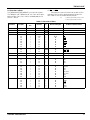
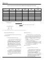
(2)
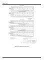
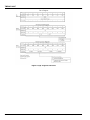
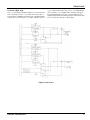
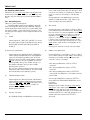
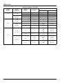
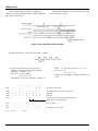
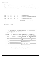
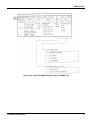
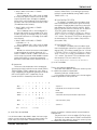
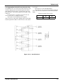
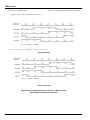
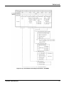
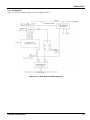
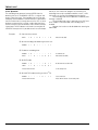
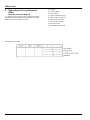
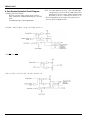
Mode 1 (7-bit UART Mode)
The 7-bit mode can be set by setting serial channel
mode register SC0MOD <SM1, 0> /SC1MOD <SM1,
0> to “01”.
In this mode, a parity bit can be added, and the addition of a parity bit can be enabled or disabled by serial
channel control register SC0CR <PE> /SC1CR <PE>,
and even parity or odd parity is selected by SC0CR
<EVEN> /SC1CR <EVEN> when <PE> is set to “1”
(enable).
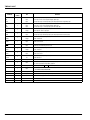
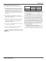
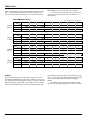
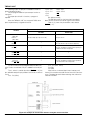
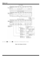
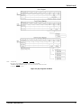
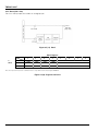
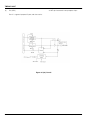
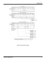
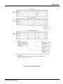
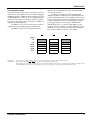
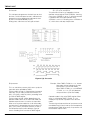
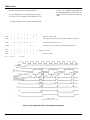
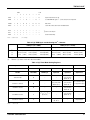
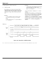
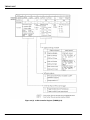
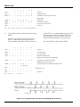
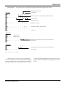
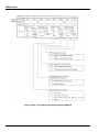
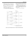
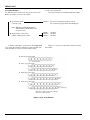
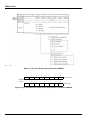
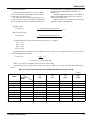
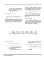
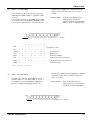
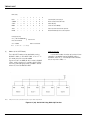
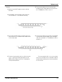
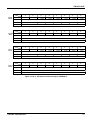
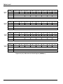
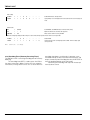
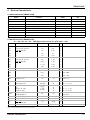
Setting example:
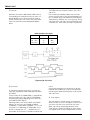
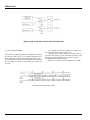
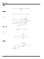
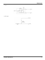
When transmitting data with the
following format, the control
registers should be set as described
below. Channel 0 is explained here.
Direction of transmission (transmission rate: 2400 bps @ fc = 12.288MHz)
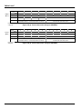
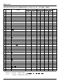
7
5
4
3
2
1
0
P9CR
←
x
x
–
–
–
–
–
1
P9FC
←
x
x
–
x
–
x
x
1
) Select P90 as the TxD pin.
SC0MOD
←
x
0
–
x
0
1
0
1
Set 7-bit UART mode.
SC0CR
←
x
1
1
x
x
x
0
0
Add an even parity.
BR0CR
←
0
x
1
0
0
1
0
1
Set transfer rate at 2400 bps.
TRUN
←
1
x
–
–
–
–
–
–
Start the prescaler for the baud rate generator.
INTES0
←
1
1
0
0
–
–
–
–
Enable INTTX0 interrupt and sets interrupt level 4.
SC0BUF
←
*
*
*
*
*
*
*
*
Set data for transmission.
Note:
(3)
6
x; don’t care
–; no change
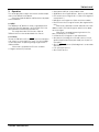
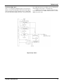
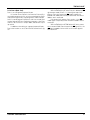
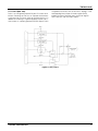
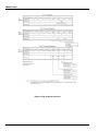
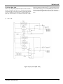
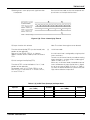
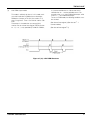
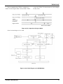
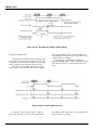
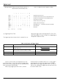
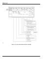
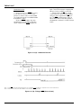
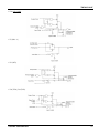
Mode 2 (8-bit UART Mode)
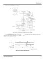
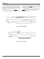
The 8-bit UART mode can be specified by setting
SC0MOD <SM1, 0> / SC1MOD <SM1, 0> to “10”. In
this mode, parity bit can be added, the addition of a
parity bit is enabled or disabled by SC0CR <PE> /
SC1CR <PE>, and even parity or odd parity is selected
by SC0CR <EVEN>/SC1CR <EVEN> when <PE> is
set to “1” (enable).
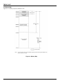
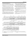
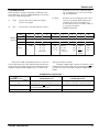
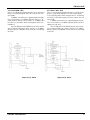
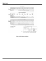
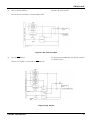
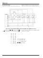
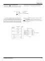
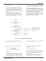
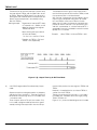
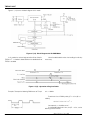
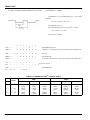
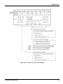
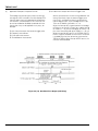
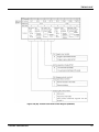
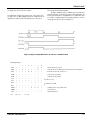
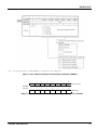
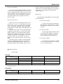
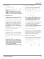
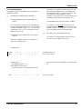
Setting example:
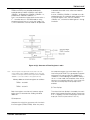
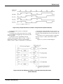
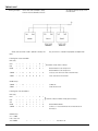
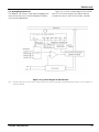
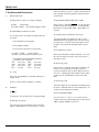
When receiving data with the
following format, the control register
should be set as described below.
Direction of transmission (transmission rate: 9600 bps @ fc = 12.288MHz)
TOSHIBA CORPORATION
135