1
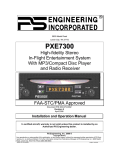
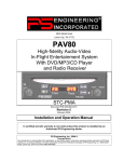
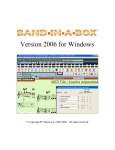
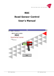
TRC RS372 Radio Stack
User Manual
The ultimate Flight Simulator Radio Stack
TRC Development b.v. – The Netherlands
USER MANUAL - TRC RS372 Radio Stack for Flight Simulation
Contents
1. Introduction ...................................................................................................................................4
About this manual......................................................................................................................4
How close to reality ...................................................................................................................4
How does it work .......................................................................................................................4
What else is needed..................................................................................................................5
2. Software Installation .....................................................................................................................6
General......................................................................................................................................6
Installation for Microsoft FS2002 / 2004....................................................................................6
3. Activating the Radio Stack modules .............................................................................................6
4. Hardware Installation ....................................................................................................................8
Installation of the complete TRC RS372 Radio Stack...............................................................8
Installation of modules...............................................................................................................8
5. The RSC Interface Board .............................................................................................................9
6. Software Development Kit (SDK) .................................................................................................9
7. Simulated KMA 28 Audio Panel ................................................................................................ 11
Operation ................................................................................................................................... 11
8. Simulated KX 155A, VHF Com/Nav Transceiver ...................................................................... 12
Operation ................................................................................................................................... 12
9. Simulated KN 62A/KN 64 TSO’d Digital DMEs ......................................................................... 15
Operation ................................................................................................................................... 15
Distance/Groundspeed/TTS GS/T Mode. .............................................................................. 16
Distance/Groundspeed/TTS RMT Mode................................................................................ 16
Prior to Lock On...................................................................................................................... 16
Operational Notes................................................................................................................... 17
10. Simulated KR 87 ADF System ................................................................................................ 18
Operation................................................................................................................................ 18
Frequency Selection............................................................................................................... 18
Operating Modes .................................................................................................................... 19
Operating the Timers.............................................................................................................. 19
11. Simulated KT 76C Panel-Mounted Transponder .................................................................... 20
General ...................................................................................................................................... 20
Operating the KT 76C ............................................................................................................ 20
Altitude Display....................................................................................................................... 20
CLR Button ............................................................................................................................. 21
VFR Button ............................................................................................................................. 21
Reply Indicator........................................................................................................................ 21
Important Codes ..................................................................................................................... 21
12. Simulated KAP 140 Autopilot .................................................................................................. 22
Two Axis with Altitude Preselect Operation ............................................................................... 22
Operation ................................................................................................................................... 22
1. AUTOPILOT ENGAGE/DISENGAGE ................................................................................ 22
2. HEADING (HDG) MODE SELECTOR ............................................................................... 22
Page 2
USER MANUAL - TRC RS372 Radio Stack for Flight Simulation
3. NAVIGATION (NAV) MODE............................................................................................... 22
4. APPROACH (APR) MODE................................................................................................. 23
5. BACK COURSE APPROACH ............................................................................................ 23
6. ALTITUDE HOLD (ALT) MODE ......................................................................................... 23
7. VERTICAL TRIM (UP/DN) BUTTONS ............................................................................... 23
8. ALTITUDE HOLD/VERTICAL SPEED DISPLAY............................................................... 23
9. PITCH MODE DISPLAY..................................................................................................... 23
10. ROLL MODE DISPLAY .................................................................................................... 23
11. AUTOPILOT ENGAGED (AP).......................................................................................... 23
Heading Select (HDG) Mode .............................................................................................. 24
Navigation (NAV) Mode Using a DG from HDG Mode (45° Intercept) ............................... 24
Navigation (NAV) Mode Using a DG from ROL Mode (All Angle Intercept)....................... 24
Navigation (NAV) Mode Using an HSI................................................................................ 25
Approach (APR) Mode Using a DG from HDG Mode (45° Intercept)................................. 25
Approach (APR) Mode Using a DG from ROL Mode (All Angle Intercept) ........................ 26
Approach (APR) Mode Using an HSI ................................................................................. 26
Back Course (REV) Mode Using a DG from HDG Mode (45° Intercept) ........................... 27
Back Course (REV) Mode Using a DG from ROL Mode (All Angle Intercept) ................... 27
Back Course (REV) Mode Using an HSI ............................................................................ 27
System Operating Modes....................................................................................................... 28
Vertical Speed (VS) Mode .................................................................................................. 28
Altitude Hold (ALT) Mode ................................................................................................... 29
13. Rotary Encoders ...................................................................................................................... 30
14. Technical Data......................................................................................................................... 31
Page 3
USER MANUAL - TRC RS372 Radio Stack for Flight Simulation
1. Introduction
TRC's Radio Stack RS372 for Flight Simulation is so realistic that you can hardly tell the
difference between the simulated Radio Stack and the real Bendix King Silver Line* products.
Modelled after the popular Bendix King Silver Line Radio Stack, as used a.o. in the Cessna 172
Skyhawk, all details are precisely reproduced extremely close to the exact dimensions of the
original radios.
Each radio is separately mounted. You can therefore fit the radios in your panel in random order.
The RS372 Radio Stack is designed to be driven from a Personal Computer via USB.
The RS372 Radio Stack is the ultimate training device for pilots and flight simulator enthusiasts.
About this manual
The functionality described in this manual is the functionality you may expect using the TRC
RS372 Radio Stack with Microsoft Flight Simulator version 2002 or version 2004.
How close to reality
Contrary to most available avionics for flight simulation, the TRC RS372 Radio Stack doesn’t use
standard 7-segment displays, but instead special, custom made displays which shows all the
indicators and segments as on the real radio stack on the exact positions.
As the functionality of the TRC RS372 Radio Stack depends on the supported functions from the
used Flight Simulator Software, not all functionality can be supported in for example Microsoft
Flight Simulator (versions 2002/2004). However, some functions, not supported, are created
using available parameters where possible.
Text in red color on the next pages indicates which functions are supported when used
with Microsoft Flight Simulator 2002/2004, due to limited availability of parameters.
All other switch and display functionalities are supported via the RSC Software Development Kit.
How does it work
The TRC RS372 Radio Stack is a set of modules, which internal construction contains switches,
rotary encoders, an LCD Display with driver integrated circuits (where applicable) and Printed
Circuit Boards.
Each module is connected to the so-called RSC (Radio Stack Controller), an electronics board
containing a stand-alone microprocessor. This board is connected to the Personal Computer
where the flight simulator software is running on via USB.
The firmware (software which runs on the RSC) is downloaded automatically from the PC every
time the RSC is powered up. This assures the user of having the latest software version running
on the RSC.
The interface software, which controls the functionality of the TRC RS372 Radio Stack is running
on the background of the Personal Computer where the flight simulator software is running on.
This process does not slow down your PC in any way.
Page 4
USER MANUAL - TRC RS372 Radio Stack for Flight Simulation
It is necessary to install the driver software prior to connecting the hardware to your PC. Please
read the instructions for software installation first.
What else is needed
In order for the TRC RS372 Radio Stack to function with Microsoft Flight Simulator version 2002,
you will need FSUIPC version 2.96 from Pete Dowson. FSUIPC 2.96 is needed for the RSC Link
Interface software to communicate with FS2002 and is developed by Pete Dowson as Freeware.
The FSUIPC version 2.96 can be downloaded from the Support section (Download Software) on
www.therealcockpit.com or www.simkits.com .
In order for the TRC RS372 Radio Stack to function with Microsoft Flight Simulator version 2004,
you will need the payware FSUIPC version 3.04 or later.
This version of FSUIPC can be downloaded from http://www.schiratti.com/dowson.html.
Page 5
USER MANUAL - TRC RS372 Radio Stack for Flight Simulation
2. Software Installation
General
Please download the latest TRC RS372 Radio Stack software from the support section at
www.therealcockpit.com or www.simkits.com . It is recommended to check regularly if there are
new software drivers available, which may expand or improve the functionality of the TRC RS372
Radio Stack.
The TRC RS372 Radio Stack will only function on the following Operation Systems:
- Windows 98
- Windows ME
- Windows 2000
- Windows XP (all versions)
Installation for Microsoft FS2002 / 2004
1. Create a directory c:\temp (or use that directory later when you already have such directory).
2. Download "radiodriver.zip" from the support section at www.therealcockpit.com or
www.simkits.com into the c:\temp directory.
3. Unzip the "radiodriver.zip" to c:\temp.
4. Plug in the USB cable from the TRC RS372 Radio Stack into your computer.
5. Windows will ask for a driver for the device you just plugged in, click "next". Click on "Search
for the best driver for your device", then click "next". Click on "Specify a location" and enter the
directory c:\temp, then click "next".
Windows will show a message that the correct driver has been found. Click "next", and then click
"finish".
6. Download the file "RSCSetup11.zip" from the support section www.therealcockpit.com or
www.simkits.com.
7. Unzip "RSCSetup**.zip"*) to c:\temp. Start the program "RSC**.exe" from c:\temp. This will
install a program called "RSCLink.exe" (which is needed to drive the radio stack) into C:\Program
Files\TRC Development\The Real Cockpit.
8. Run the program "RSCLink.exe". By running RSC11.exe earlier, this program is installed in:
C:\Program Files\TRC Development\The Real Cockpit.
9. When "RSCLink.exe" starts, Windows asks for the location of the drivers again. Browse to the
directory c:\temp and install the driver.
10. Download "FSUIPC.zip" or "FSUIPC304.zip", depending on which flight simulator version you
are using. The zipped file contains information on how to install the FSUIPC program.
11. Now the TRC RS372 Radio Stack should work correctly.
*) The asteridges represent the version number of the file.
Page 6
USER MANUAL - TRC RS372 Radio Stack for Flight Simulation
3. Activating the Radio Stack modules
The TRC RS372 Radio Stack is a modular system. Therefore a user can purchase all modules as
a complete system or just the modules he needs.
Due to this modularity, conflicts can arise when the TRC RS372 Radio Stack modules are used in
combination with other hardware.
Conflicts can also arise when modules are not present at the Radio Stack Controller board.
Each module can be disabled using the startup screen of the TRC RS372 Radio Stack driver
software.
By default, the modules are enabled and the Rotary Encoders (see chapter 13) are disabled.
At start up of the RSC Link, you should once, (till your hardware changes) enable or disable the
proper modules.
Figure 1
Page 7
USER MANUAL - TRC RS372 Radio Stack for Flight Simulation
4. Hardware Installation
When you ordered the TRC RS372 Radio Stack as a complete product (tower cabinet), you
should check wether the proper power setting of the Power Supply on the back of the cabinet is
set to the power available in your area.
For North America, this is 110v. 60Hz., for Europe this is 230v. 50Hz.
Incorrect setting of the power can damage your TRC RS372 Radio Stack !
Installation of the complete TRC RS372 Radio Stack
The complete TRC RS372 Radio Stack comes with a suitable power cord for Central Europe, UK
or USA. Plug this power cord into the back of the TRC RS372 Radio Stack cabinet after you have
checked for the right power setting.
Now plug in the USB cable (this cannot go wrong) into the right side of the cabinet and follow the
directions of chapter 2 and 3.
Installation of modules
When you have purchased TRC RS372 Radio Stack modules and the TRC RS372 Radio Stack
Controller (RSC) you should take care of statical electricity when handling the RSC and the
modules. Especially in very dry environments and during winter time, static electricity can ruin the
RSC easily and this is not covered by warranty. Take the normal precautions when handling
sensitive electronic devices.
The RSC comes with a USB cable to connect to your computer.
Before you mount the modules and the RSC in your own flight deck, check if the flat cables are
long enough to connect the modules to the RSC when mounted.
First connect the modules to the RSC, prior to connecting the power supply.
Each module comes with a flatcable sufficient for normal connection. Check the notch on the
connectors for the proper direction of inserting the connectors into the modules and the RSC.
The RSC should be connected to a power source. Favourably this power source is a standard PC
AT Power Supply. The RSC has a 5-1/4” PC Diskdrive Power connector. This allows you to
connect the RSC to the AT Power Supply as it was a normal 5-1/4” diskdrive.
Page 8
USER MANUAL - TRC RS372 Radio Stack for Flight Simulation
5. The RSC Interface Board
The board has connectors for all presently available radio stack modules and is already prepared
for the future modules Moving Map and GPS.
Power
Connector
USB
Connector
Rotary
Encoders
DME
Autopilot
ADF
NAV/COM 2
NAV/COM 1
Transponder
Moving
Map*)
Audio Panel
GPS*)
Figure 2
*) Future expansion
Page 9
USER MANUAL - TRC RS372 Radio Stack for Flight Simulation
6. Software Development Kit (SDK)
TRC Development provides a so-called SDK for the Radio Stack.
With the SDK a programmer is able to control the TRC RS372 Radio Stack from any flight
simulator or simulation software by simply using function calls.
To use the Radio Stack SDK, programming skills are required. It is beyond the scope of the SDK
manual and beyond TRC Development to learn you how to program.
TRC Development will therefore not give any support on general programming questions, but on
serious bug reporting on the SDK only.
Basically, with the use of the Radio Stack SDK, there is no limit to use the Radio Stack Devices
from any type of software written by yourself.
With the Radio Stack SDK, you can read and write values directly to and from the Radio Stack
Devices.
The Radio Stack SDK can be used to write software in one of the following programming
languages:
Language/Environment:
1. Microsoft Visual C++
2. Borland C++ Builder
3. Microsoft Visual Basic
4. Borland Delphi
The Radio Stack SDK manual introduces how to use the Radio Stack SDK variables for the
different programming environments.
The Radio Stack SDK manual and SDK software can be downloaded from the support section at
www.therealcockpit.com or www.simkits.com.
Page 10
USER MANUAL - TRC RS372 Radio Stack for Flight Simulation
7. Simulated KMA 28 Audio Panel
Marker Beacon Sensitivity &
Test/Mute Select
Marker Beacon
Indicator Lamps
Mic Selector
Receive Audio Selectors
Intercom Mode Select
Intercom Volume
Speaker Switch
Crew ICS/Music 1 Mute
Swap Indicator
Transmit Indicator
Figure 3
Operation
The Simulated KMA28 Audio Panel’s functions supported from Microsoft Flight Simulator
versions 2002 and 2004 are described in red. For support of remaining functions, please check
the SDK (Software Development Kit).
Receiver audio is selected through two momentary and six latched, pushbutton, backlit switches.
Com 1 and Com 2 are the momentary switches. The latched function is simulated by the LED
which is lighted in the IN position and not lighted in the OUT position.
The users can identify which receivers are selected by noting which of the green switch LEDs is
illuminated.
Push buttons labeled Nav 1, Nav 2, DME, MKR (Marker), ADF, AUX (auxiliary), and SPR
(Speaker) are "latched" type switches. When one of these buttons is pressed, it will stay in the
"in" position, illustrated by a LED. Press the switch again and it be in the "out" position and
remove that receiver from the audio.
Page 11
USER MANUAL - TRC RS372 Radio Stack for Flight Simulation
8. Simulated KX 155A, VHF Com/Nav Transceiver
“T” Indicates Mic Button is Being Depressed
“R” Indicates Squelch is Open by Received Signal
Active Comm
Frequency
Channel
Indicator
On/Off Comm
Volume Knob.
Pull to disable
Comm Receiver
Automatic Squelch.
Push in for
Automatic Squelch.
Standby Comm
Frequency
Comm Frequency
Transfer Button
Active Nav
Frequency
Comm Frequency
Select Knobs
Channel
Button
Standby Nav
Frequency
Nav Frequency
Transfer Button
Nav Audio
Volume Control.
Pull to Hear
Morse Code
Nav Ident.
CDI
(Course Deviation
Indicator)
Nav Frequency
Select Knob
Nav Mode
Button
Figure 4
Operation
The Simulated KX155A COM/NAV Transceiver’s functions supported from Microsoft Flight
Simulator versions 2002 and 2004 are described in red. For support of remaining functions,
please check the SDK (Software Development Kit).
Rotate the VOL knob clockwise from the OFF position. Select the desired operating frequency in
the standby display by rotating the Frequency Select Knobs either clockwise or counterclockwise.
A clockwise rotation will increment the previous frequency while a counterclockwise rotation will
decrement the previous frequency.
The outer knob will change the MHz portion of the standby display. At one band-edge (118 or 136
MHz) the following 1 MHz change will wrap around to the other band-edge.
The inner knob will change the kHz portion of the standby display. It will change in increments of
50 kHz when the knob is pushed in and 25 kHz when the knob is pulled out. The frequency wrap
around at the edge of the band is also utilized when incrementing or decrementing the kHz
portion of the standby display.
To tune the radio to the desired operating frequency, the desired frequency must be entered into
the standby display (Figure 5) and then the transfer button must be pushed.
Page 12
USER MANUAL - TRC RS372 Radio Stack for Flight Simulation
Figure 5. Frequency entered in standby display
This will trade the contents of the active and standby displays (Figure 6).
Figure 6, Active/standby frequencies toggle
The operating frequency can also be entered by accessing the ACTIVE ENTRY (direct tune)
mode which is done by pushing and holding the COMM TRANSFER button for 2 or more
seconds. In the direct tune mode, only the active part of the display is visible (Figure 7).
Figure 7. Frequency entered in active entry mode
The desired frequency can be directly entered into the display.
Push the COMM TRANSFER button again to return to the active/standby display.
The transceiver is always tuned to the frequency appearing in the ACTIVE display. It is therefore
possible to have two different frequencies stored in the ACTIVE and STANDBY displays and to
change back and forth between them at the simple push of the transfer button.
The KX 155A also has provisions to program 32 channels. Pressing the CHAN button for 2 or
more seconds will cause the unit to enter the channel program mode. Upon entering the channel
Page 13
USER MANUAL - TRC RS372 Radio Stack for Flight Simulation
program mode, “PG” is displayed next to the channel number and the channel number will flash
indicating that it can be programmed.
The desired channel can be selected by turning the comm kHz knob. The channel frequency can
be entered by pushing the COMM TRANSFER button which will cause the standby frequency to
flash. The comm frequency knobs are then used to enter the desired frequency. Additional
channels may be programmed by pressing the COMM TRANSFER button and using the same
procedure. To exit the program mode and save the channel information, momentarily push the
CHAN button. This will cause the unit to return to the previous frequency entry mode.
The channel selection mode can then be entered by momentarily pushing the CHAN button. “CH”
is displayed next to the last used channel number. The comm frequency knobs can be used to
select the desired channel. The unit will automatically exit the channel mode, with the channel
frequency remaining in the STANDBY window, if no channel is selected within 5 seconds after
entering the channel selection mode. The channel frequency is then made the ACTIVE frequency
in the normal manner by pressing the COMM TRANSFER button.
NAV Receiver
The right portion of the display is allocated to NAV receiver information. The frequency
channeling is similar to the COMM when operating in the frequency mode (Figure 7). The NAV
increment/ decrement knobs are located on the right hand side of the front panel. The outer knob
operates in 1 MHz steps and increments/decrements the STANDBY frequency display. The inner
knob operates in 50 kHz steps. The NAV receiver’s lower and upper frequency limits are 108.00
MHz and 117.95 MHz. Exceeding the upper limit of frequency band will automatically return to the
lower limit and vice versa.
Depressing the NAV frequency transfer button for 2 seconds or more will cause the display to go
in to the ACTIVE ENTRY mode. Only the ACTIVE frequency will be displayed and it can be
directly changed by using the NAV inc/dec knobs.
The display will return to the ACTIVE/STANDBY mode when the NAV frequency transfer button is
pushed.
Depressing the mode button will cause the NAV display to go from the ACTIVE/STANDBY format
to the ACTIVE/CDI (Course Deviation Indicator) format. The vertical “needle” moves side to side
similar to a mechanical CDI. When the needle is centered, the aircraft is on the selected OBS
course. When the active frequency is tuned to a VOR frequency, the center of the CDI scale
displays the “TO” or “FROM” indicator.
In the CDI mode, the increment/decrement knob (pushed in) channels the ACTIVE frequency
window and depressing the frequency transfer button will cause the ACTIVE frequency to be
placed in blind storage and the STANDBY frequency (in blind storage) to be displayed in the
ACTIVE window display. When the ACTIVE window is tuned to a VOR frequency, the standby
frequency area is replaced by a three digit OBS (Omni Bearing Selector) display. The desired
OBS course can be selected by pulling out the inner NAV frequency knob and turning it. This
OBS display changes the OBS course on the associated VOR indicator. An “OBS” in the middle
of the NAV display will flash while the inner NAV frequency knob is pulled out. The CDI is
displayed on the line below the frequency/OBS.
When the received signal is too weak to ensure accuracy the display will indicate “FLAG”.
Another push of the mode button will return to the ACTIVE/STANDBY format.
When the smaller increment/decrement knob is pushed in, depressing the NAV TRANSFER
button will interchange the ACTIVE and STANDBY frequencies.
Page 14
USER MANUAL - TRC RS372 Radio Stack for Flight Simulation
9. Simulated KN 62A/KN 64 TSO’d Digital DMEs
7-Segment
LCD Displays
3-Position Function Switch for:
• Remote (RMT) Tuning
• Frequency (FREQ) Readout
• Groundspeed/Time-to-Station (GS/T) Readout
ON/OFF
Switch
Figure 8
Frequency
Selector
Knobs
Operation
The Simulated KN62A/KN64’s functions supported from Microsoft Flight Simulator versions 2002
and 2004 are described in red. For support of remaining functions, please check the SDK
(Software Development Kit).
The 3-position function switch determines both the information displayed and the channeling
source. Place the function switch on Frequency (FREQ). The unit is channeled internally with its
own two concentric frequency selection knobs. The smaller of the two knobs has an “in” and an
“out” position. When in the “in” position, this smaller knob changes the 0.1 MHz digit (0.0, 0.1, 0.2,
etc.). When pulled “out”, it changes in 0.05 MHz steps, wrapping around at 0.00 and 0.95
MHz.The outer, larger knob changes the larger digits (1 MHz, 10 MHz). In FREQ mode, the unit
will display distance and the selected frequency. (See Figure 8.)
Figure 9. Distance/Frequency FREQ Mode
Now move the function switch to the Groundspeed/Time-to-Station (GS/T) position. The unit will
hold the internally selected frequency and will display distance, groundspeed and time-to-station.
(See Figure 9.)
Page 15
USER MANUAL - TRC RS372 Radio Stack for Flight Simulation
Distance/Groundspeed/TTS GS/T Mode.
Rotating the frequency selector will have no effect on the display, because the DME is in
“Frequency Hold”. This frequency hold feature in the GS/T mode prevents accidental
rechanneling of the DME when the frequency is not displayed.
MIN
Figure 10. Distance/Groundspeed/TTS GS/T Mode
Place the function switch in the Remote (RMT) position, and your DME will be channeled when
you select your NAV frequency on the NAV receiver. Search time is usually about one second.
When the unit locks on a ground station, it will display distance, groundspeed and time-to-station.
(See Figure 10.)
Distance/Groundspeed/TTS RMT Mode.
Prior to lock on, “dashes” will be displayed. (See Figure 11.)
MIN
Figure 11. Prior to Lock On.
Prior to Lock On.
Note that you may have two frequencies available at all times (one remotely selected on the NAV
receiver and one internally selected with the unit’s controls).
RMT
MIN
MIN
Figure 12. Distance/Groundspeed/TTS RMT Mode
Page 16
USER MANUAL - TRC RS372 Radio Stack for Flight Simulation
Operational Notes
The unit electronically converts to distance the elapsed time required for signals to travel to and
from the ground station. This distance is then indicated in nautical miles on the Distance/
Speed/Time-to-Station display. This distance, commonly referred to as slant range distance,
should not be confused with actual along-the-ground distance.
The difference between actual ground distance and slant range is least at low altitude and/or long
range. If the range is three times the altitude or greater, error is negligible.
The effective range of DME depends on many factors, most important being the altitude of the
aircraft. Other contributing factors are the location and elevation of the station, DME transmitter
power output, and receiver sensitivity.
The groundspeed feature incorporated in the unit measures the rate of change in DME slant
range distance with time. This speed is then read from 0 to 999 knots in 1 knot increments. To
obtain accurate groundspeed, the aircraft must be tracking directly to or from the station. To
obtain accurate time to station, the aircraft must be tracking directly to the station.
Page 17
USER MANUAL - TRC RS372 Radio Stack for Flight Simulation
10. Simulated KR 87 ADF System
ANT/ADF
Mode Annunciation
Select ANT mode
(out position)
Select ADF mode
(in position)
BFO
Annunciation
IN USE
Frequency
Select
BFO
Button
Frequency
Transfer
Button
STANDBY
Frequency
Annunciation
Select FLIGHT
TIMER or
ELAPSED TIMER
STANDBY Frequency,
FLIGHT TIME or
ELAPSED TIME
Set and Reset
ELAPSED TIMER
Flight timer and
Elapsed timer
mode annunciation
ON/OFF/VOL
Control Switch
Frequency
Select
Knobs
Figure 13
Operation
The Simulated KR87 ADF System’s functions supported from Microsoft Flight Simulator versions
2002 and 2004 are described in red. For support of remaining functions, please check the SDK
(Software Development Kit).
Rotate the ON/OFF/VOL knob clockwise from the detented “OFF” position. The unit will be
activated and will be ready to operate.
Frequency Selection
The active frequency (to which the ADF is tuned) is displayed in the left side of the window at all
times. A standby frequency is displayed in the right side when “FRQ” is annunciated.
With “FRQ” annunciated, the standby frequency is selected using the frequency select knobs
which may be rotated either clockwise or counterclockwise.
Pull the small inner knob out to tune 1’s. Push the smaller inner knob in to tune 10’s. The outer
knob tunes the 100’s and the 1000’s up to 1699.
The standby frequency selected may then be put into the active window by pressing the “FRQ”
button. The standby and active frequencies will be exchanged (flip-flopped), the new frequency
will become active, and the former active frequency will go into standby.
Note: Microsoft Flight Simulator allows setting the frequency in 0.5 kHz steps, and requires the
exact frequency to be used. The Simulated KR 87 ADF System, like the real thing, sets the
frequency in 1 kHz steps, and automatically scans for a signal within 0.5 kHz from the selected
frequency. E.g., a frequency of 323.5 can be picked up by setting the frequency on the Simulated
KR 87 ADF System to either 323.0 kHz or 324 kHz.
Page 18
USER MANUAL - TRC RS372 Radio Stack for Flight Simulation
Operating Modes
Antenna (ANT) mode is selected and annunciated when the “ADF” button is in the “out” position.
Figure 14. ANT Mode selected
The ADF mode is selected and annunciated when the “ADF” button is in the depressed position.
Figure 15. ADF Mode selected
Outside of the United States some stations are unmodulated and use an interrupted carrier for
identification purposes. The BFO mode, activated and annunciated when the “BFO” button is
depressed, permits the carrier wave and the associated Morse code identifier broadcast on the
carrier wave to be heard.
Operating the Timers
The flight timer will always be automatically reset to :00 whenever power is interrupted either by
the avionics master switch or the unit s ON/OFF switch. Always read flight time prior to power
shutdown.
Flight time or elapsed time are displayed and annunciated alternatively by depressing the FLT/ET
button. The flight timer continues to count up until the unit is turned off. The elapsed timer may be
reset back to :00 by pressing the SET/RST button. It will then start counting up again. (NOTE:
pressing the SET/RST button will reset the elapsed timer whether it is being displayed or not.)
NOTE: The standby frequency which is in memory while flight time or elapsed time modes are
being displayed may be called back by pressing the FRQ button, then transferred to active use by
pressing the FRQ button again.
While FLT or ET is displayed the in use frequency on the left side of the window may be
changed, by using the frequency select knobs, without any effect on the stored standby frequency
or the other modes. This feature is especially useful when searching for stations with unknown
frequencies.
Page 19
USER MANUAL - TRC RS372 Radio Stack for Flight Simulation
11. Simulated KT 76C Panel-Mounted Transponder
IDT
Button
Altitude
Window
Reply
Indicator
Code Entry
Buttons
Function
Selector
Knob
Code
Window
CLR
Button
VFR
Button
Figure 16
General
The Simulated KT76C Transponder’s functions supported from Microsoft Flight Simulator
versions 2002 and 2004 are described in red. For support of remaining functions, please check
the SDK (Software Development Kit).
In real life, your simulated transponder is a radio transmitter and receiver which operates on radar
frequencies. Receiving ground radar interrogations at 1030 MHz, it returns a coded response of
pulses to groundbased radar on a frequency of 1090 MHz. As with other Mode A/Mode C
transponders, the KT 76C replies with any one of 4,096 codes, which differ in the position and
number of pulses transmitted. By “replying” to ground transmissions, your KT 76C enables ATC
computers to display aircraft identification, altitude and ground speed on Enroute, Approach or
Departure Control radar screens.
Operating the KT 76C
Select the proper reply code by pressing the desired code entry buttons. The reply code will be
displayed in the code window.
Altitude Display
The KT 76C displays Flight Level Altitude, marked by the letters “FL” and a number in hundreds
of feet, on the left side of the display. For example, the reading “FL 065” corresponds to the
altitude of 6,500 feet, referenced to 29.92 inches of mercury (or 1013 hP) at sea level. Flight
Level Altitude represents “pressure altitude,” and should not be confused with true altitude. Flight
Level Altitude is displayed only when altitude reporting is enabled. If the altitude window is blank
or shows a series of dashes (as in the case of an invalid altimeter code being reported), altitude
reporting will be disabled.
Page 20
USER MANUAL - TRC RS372 Radio Stack for Flight Simulation
CLR Button
Code entry mistakes are corrected, one digit at a time, by pressing the CLR button and reentering
the correct code. The last active code will be displayed if a complete four-digit code has not been
entered and there is no activity on any of the code entry buttons, the VFR button, or the CLR
button for four seconds.
VFR Button
Momentarily pressing the VFR button will enter a pre-programmed VFR code, typically 1200, in
the code window. Pressing and holding the VFR button for two seconds will cause the last active
code to be displayed.
Reply Indicator
The reply indicator blinks to indicate that the KT 76C is functioning properly and replying to
interrogations.
Important Codes
7700 - Emergency
7600 - Communication Failure
7500 - Hijacking
0000 - Military - DO NOT USE!
See the Aeronautical Information Manual (AIM) for detailed explanation of these codes and their
use.
Page 21
USER MANUAL - TRC RS372 Radio Stack for Flight Simulation
12. Simulated KAP 140 Autopilot
Two Axis with Altitude Preselect Operation
Autopilot
engaged
annunciation
Roll Mode
display
P
Pitch Mode
display
Pitch Trim
annunciation
Altitude Alert
annunciation
Altitude Alert/
Vertical Speed/
Baro Setting
Display
Altitude
Arm
button
Baro Set
button
R
Autopilot
engage/
disengage
button
Roll Axis
Annunciator
Navigation Mode
selector button
Heading Mode
selector button
Back Course
Approach
selector button
Approach Mode
selector button
Pitch Axis
Annunciator
Vertical
Trim
buttons
Altitude Hold
Mode
selector button
Rotary Knobs
altitude alert
reference
Figure 17
Operation
The Simulated KAP140 Autopilot’s functions supported from Microsoft Flight Simulator versions
2002 and 2004 are described in red. For support of remaining functions, please check the SDK
(Software Development Kit).
1. AUTOPILOT ENGAGE/DISENGAGE
(AP) BUTTON - When pushed, engages autopilot if all logic conditions are met. The autopilot will
engage in the basic roll (ROL) mode which functions as a wing leveler. When pressed again, will
disengage the autopilot. The AP button must be pressed and held for 0.25 seconds to engage
the autopilot.
2. HEADING (HDG) MODE SELECTOR
BUTTON - When pushed, will arm the Heading mode, which commands the airplane to turn to
and maintain the heading selected by the heading bug on either the DG or HSI. A new heading
may be selected at any time and will result in the airplane turning to the new heading. Button can
also be used to toggle between HDG and ROL modes.
3. NAVIGATION (NAV) MODE
SELECTOR BUTTON - When pushed, will arm the navigation mode. The mode provides
automatic beam capture and tracking of VOR, LOC or GPS as selected for presentation on the
Page 22
USER MANUAL - TRC RS372 Radio Stack for Flight Simulation
HSI or CDI. NAV mode is recommended for enroute navigation tracking. NAV mode may also be
used for front course LOC tracking when GS tracking is not desired.
4. APPROACH (APR) MODE
SELECTOR BUTTON - When pushed, will arm the Approach mode. This mode provides
automatic beam capture and tracking of VOR, GPS, LOC, and Glideslope
(GS) on an ILS, as selected for presentation on the HSI or CDI. APR mode is recommended for
instrument approaches.
5. BACK COURSE APPROACH
(REV) MODE SELECTOR BUTTON - When pushed, will arm the Back Course approach mode.
This mode functions similarly to the approach mode except that the autopilot response to LOC
signals is reversed, and GS is disabled.
6. ALTITUDE HOLD (ALT) MODE
SELECT BUTTON - When pushed, will select the Altitude Hold mode. This mode provides
tracking of the selected altitude.
7. VERTICAL TRIM (UP/DN) BUTTONS
- The action of these buttons is dependent upon the vertical mode present when pressed. If VS
mode is active, immediate button strokes will increment the vertical speed commanded either up
or down at the rate of 100 ft/min per button press. If ALT mode is active, incremental button
strokes will move the altitude hold reference altitude either up or down at 20 feet per press.
8. ALTITUDE HOLD/VERTICAL SPEED DISPLAY
In VS hold, displays the commanded vertical speed. In altitude hold, displays the selected
reference altitude.
9. PITCH MODE DISPLAY
Displays the active and armed pitch modes (VS, ALT, ARM and GS).
10. ROLL MODE DISPLAY
Displays the active and armed roll modes (ROL, HDG, NAV ARM, NAV, APR ARM, APR, REV
ARM, REV, GS ARM).
11. AUTOPILOT ENGAGED (AP)
ANNUNCIATION - Illuminates whenever the autopilot is engaged.
Page 23
USER MANUAL - TRC RS372 Radio Stack for Flight Simulation
Heading Select (HDG) Mode
In the heading mode, the autopilot will fly a selected heading. The following steps should be taken
to operate in the heading mode:
Figure 18. HDG Mode selected
1. Move the heading “bug” to the desired heading on the DG or HSI using the Heading Select
knob.
2. Engage autopilot - Press AP. The AP button must be pressed and held for 0.25 seconds to
engage the autopilot.
3. Depress the HDG button on the KAP 140 to engage the heading select mode. The autopilot
will turn the aircraft in the shortest direction to intercept and fly the heading.
4. If you move the heading “bug” again while the heading select mode is engaged, the autopilot
will immediately turn the aircraft in the direction of the newly selected heading.
5. Press HDG button again and the autopilot will return to the ROL mode.
Navigation (NAV) Mode Using a DG from HDG Mode (45° Intercept)
In the navigation (NAV) mode, the autopilot intercepts and tracks VOR/RNAV and GPS courses.
To arm NAV mode (with the KAP 140 currently in the HDG mode):
1. Select the desired frequency for VOR or RNAV. For GPS, verify the desired waypoint or
destination.
2. OBS Knob - SELECT desired course.
3. NAV Mode Selector Button - PRESS. Note NAV annunciated. NOTE: When NAV is selected,
the autopilot will flash HDG for 5 seconds to remind the pilot to reset the HDG bug to the OBS
course. Check the heading displayed on the DG against the magnetic compass and reset if
necessary.
4. Heading Selector Knob - ROTATE BUG to agree with OBS course. Note Instruments: CDI
needle to left. Intercept heading 45° to the left of selected (heading bug) course.
Navigation (NAV) Mode Using a DG from ROL Mode (All Angle Intercept)
In the navigation (NAV) mode, the autopilot intercepts and tracks VOR/RNAV and GPS courses.
To arm NAV mode (with the KAP 140 currently in the ROL mode):
1. Maneuver the aircraft to the desired intercept angle prior to selecting ROL mode.
2. Select the desired frequency for VOR or RNAV. For GPS, verify the desired waypoint or
destination.
3. OBS Knob - SELECT desired course.
Page 24
USER MANUAL - TRC RS372 Radio Stack for Flight Simulation
4. NAV Mode Selector Button - PRESS. Note NAV annunciated. NOTE: When NAV is selected,
the autopilot will flash HDG for 5 seconds to remind the pilot to reset the HDG bug to the OBS
course. Check the heading displayed on the DG against the magnetic compass and reset if
necessary.
5. Heading Selector Knob - ROTATE BUG to agree with OBS course. Note Instruments: CDI
needle to left. Intercept heading 30° to the left of selected (heading bug) course.
Navigation (NAV) Mode Using an HSI
In the navigation (NAV) mode, the autopilot intercepts and tracks VOR/RNAV and GPS courses.
To arm NAV mode (with the KAP 140 currently in the HDG mode):
Figure 19. Approach Mode selected
1. Select the desired frequency for VOR or RNAV. For GPS, verify the desired waypoint or
destination.
2. Course Bearing Pointer - SET to desired course.
3. Heading Selector Knob - SET BUG to provide desired intercept angle.
4. NAV Mode Selector Button - PRESS. Note NAV annunciated.
Approach (APR) Mode Using a DG from HDG Mode (45° Intercept)
The Approach (APR) mode allows the autopilot to intercept and track LOC, VOR/RNAV and GPS
courses. To arm APR mode (with the KAP 140 currently in the HDG mode):
Figure 20. Back Course Mode selected
1. Select the desired frequency for LOC, VOR or RNAV. For GPS, verify the desired approach.
2. OBS Knob - SELECT desired approach course. (For a localizer, set it to serve as a memory
aid.)
3. APR Mode Selector Button - PRESS. Note APR annunciated. NOTE: When APR is selected,
the autopilot will flash HDG for 5 seconds to remind the pilot to reset the HDG bug to the desired
Page 25
USER MANUAL - TRC RS372 Radio Stack for Flight Simulation
approach course. Check the heading displayed on the DG against the magnetic compass and
reset if necessary.
4. Heading Selector Knob - ROTATE BUG to agree with desired approach course. Note
Instruments: CDI needle to left. Intercept heading 45° to the left of
selected (heading bug) course.
Approach (APR) Mode Using a DG from ROL Mode (All Angle Intercept)
The Approach (APR) mode allows the autopilot to intercept and track LOC, VOR/RNAV and GPS
courses. To arm APR mode (with the KAP 140 currently in the ROL mode):
P
R
Figure 21. Back Course Mode using DG from ROL Mode
1. Maneuver the aircraft to the desired intercept angle prior to selecting ROL mode.
2. Select the desired frequency for LOC, VOR or RNAV. For GPS, verify the desired approach.
3. OBS Knob - SELECT desired approach course. (For a localizer, set it to serve as a memory
aid.)
4. APR Mode Selector Button - PRESS. Note APR annunciated. NOTE: When APR is selected,
the autopilot will flash HDG for 5 seconds to remind the pilot to reset the HDG bug to the desired
approach course. Check the heading displayed on the DG against the magnetic compass and
reset if necessary.
5. Heading Selector Knob - ROTATE BUG to agree with desired approach course. Note
Instruments: CDI needle to left. Intercept heading 30° to the left of selected (heading bug) course.
Approach (APR) Mode Using an HSI
The Approach (APR) mode allows the autopilot to intercept and track LOC, VOR/RNAV and GPS
courses. To arm APR mode (with the KAP 140 currently in the HDG mode):
Figure 22. Back Course Mode using an HSI
1. Select the desired frequency for LOC, VOR or RNAV. For GPS, verify the desired approach.|
2. Course Bearing Pointer – SET to desired course.
Page 26
USER MANUAL - TRC RS372 Radio Stack for Flight Simulation
3. Heading Selector Knob - SET BUG to provide desired intercept angle.
4. APR Mode Selector Button - PRESS. Note APR annunciated.
Back Course (REV) Mode Using a DG from HDG Mode (45° Intercept)
The Back Course (REV) mode allows the autopilot to intercept and track a localizer back course.
To arm REV mode (with the KAP 140 currently in the HDG mode):
1. Select the desired frequency for LOC.
2. OBS Knob - SELECT front course inbound heading.
3. REV Mode Selector Button - PRESS. Note REV annunciated. NOTE: When REV is selected,
the autopilot will flash HDG for 5 seconds to remind the pilot to reset the HDG bug to the front
course inbound heading. Check the heading displayed on the DG against the magnetic compass
and reset if necessary.
4. Heading Selector Knob - ROTATE BUG to agree with the FRONT COURSE inbound heading.
Note Instruments: CDI needle to the right. Intercept heading 45° to the left of the back course.
Back Course (REV) Mode Using a DG from ROL Mode (All Angle Intercept)
The Back Course (REV) mode allows the autopilot to intercept and track a localizer back course.
To arm REV mode (with the KAP 140 currently in the ROL mode):
1. Maneuver the aircraft to the desired intercept angle prior to selecting ROL mode.
2. Select the desired frequency for LOC.
3. OBS Knob - SELECT front course inbound heading.
4. REV Mode Selector Button - PRESS. Note REV annunciated. NOTE: When REV is selected,
the autopilot will flash HDG for 5 seconds to remind the pilot to reset the HDG bug to the front
course inbound heading. Check the heading displayed on the DG against the magnetic compass
and reset if necessary.
5. Heading Selector Knob - ROTATE BUG to agree with the FRONT COURSE inbound heading.
Note Instruments: CDI needle to the right. Intercept heading 30° to the left of the back course.
Back Course (REV) Mode Using an HSI
The Back Course (REV) mode allows the autopilot to intercept and track a localizer back course.
To arm REV mode (with the KAP 140 currently in the HDG mode):
1. Select the desired frequency for LOC.
2. Course Bearing Pointer - SET to the FRONT COURSE inbound heading.
3. Heading Selector Knob - SET BUG to provide desired intercept angle.
4. REV Mode Selector Button - PRESS. Note REV annunciated.
Page 27
USER MANUAL - TRC RS372 Radio Stack for Flight Simulation
System Operating Modes
P
R
Fig. 23. Vertical Speed Mode
Vertical Speed (VS) Mode
The Vertical Speed (VS) mode allows variable speed climbs and descents. The ALT button
toggles between altitude hold and vertical speed modes.
To operate in the VS mode (with autopilot currently disengaged):
1. AP button - Press. Note ROL, VS and current vertical speed is displayed. If no other modes are
selected the autopilot will operate in the ROL and vertical speed hold modes. The AP button must
be pressed and held for 0.25 seconds to engage the autopilot.
2. UP or DN button - Select desired climb or descent rate. Each button stroke will increment the
vertical speed commanded up or down by 100 ft/min per button press.
To initiate a climb or descent from Altitude Hold (ALT) mode:
1. ALT button - Press. Note ALT changes to VS and current vertical speed is displayed.
2. UP or DN button - Select desired climb or descent rate. Each button stroke will increment the
vertical speed commanded up or down by 100 ft/min per button press. Note: When operating at
or near the best rate of climb airspeed, at climb power settings, and using vertical speed hold, it is
easy to decelerate to an airspeed where continued decreases in airspeed will result in a reduced
rate of climb. Continued operation in vertical speed mode can result in a stall.
Page 28
USER MANUAL - TRC RS372 Radio Stack for Flight Simulation
Altitude Hold (ALT) Mode
The Altitude Hold (ALT) mode maintains the selected altitude. The ALT button toggles between
altitude hold and vertical speed modes. To operate in the ALT mode (with autopilot currently in
the Vertical Speed mode):
P
R
Fig. 24. Altitude Hold Mode
1. ALT button - Press. Note: ALT is annunciated and autopilot maneuvers to maintain selected
altitude.
2. UP or DN button - Select to change altitude. Incremented button strokes will move the
reference altitude by 20 feet per press. Note: Incremented altitude changes should be limited to
500 ft. of change.
Page 29
USER MANUAL - TRC RS372 Radio Stack for Flight Simulation
13. Rotary Encoders
The full TRC Radio Stack, delivered in cabinet, is equipped with 6 rotary encoders. These
encoders can be used in case you use a screen panel instead of TRC instruments.
The function of the encoders must be disabled when TRC gauges are used or when the
functionality conflicts with other hardware. See Chapter 3: “Activating the Radio Stack modules”
for instructions how to enable or disable the rotary encoder functions.
The functions of the rotary encoders are:
OBS1
To adjust the VOR1 Compass Ring
OBS2
To adjust the VOR2 Compass Ring
ALT
To adjust the pressure scale of the Altimeter
H-BUG
To adjust the Autopilot Heading Bug on the Heading Indicator.
HEADING
To adjust the Heading Compass Ring
ADF
To adjust the ADF Compass Ring
Page 30
USER MANUAL - TRC RS372 Radio Stack for Flight Simulation
14. Technical Data
Size of cabinet .......................................................... WxHxD: 6.7x15.7x9.5" / 170x400x240 mm.
Weight.................................................................................................................. 22 Pound/10Kg.
Voltage.................................................................................................... 110v 60Hz./230 v. 50Hz.
Power consumption ................................................................ 100 Watt (with all radios mounted)
PC Connection........................................................................................................................ USB
PC minimum requirements: (PC not included)
- Windows 98, ME, 2000, XP (all versions)
- Processor 1,5 Ghz.
- 256 Mb Memory
- 32 Mb graphics card
Page 31