1
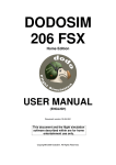
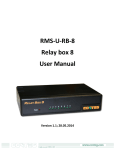
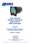
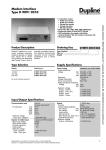
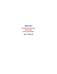
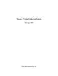
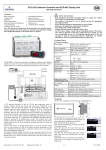
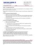
Starter Switch for Flight Simulators
Parts Number 871 722 802 34 91
The Starter Switch for Flight Simulation is constructed around a Rotary Switch combined
with high quality stainless steel mechanics
The Starter Switch has totally 5 positions, whereof the 5th position is spring returned to the
4th position. The 5th position functions as a starter position.
Once mounted, the key cannot be removed and is therefore safe against losses.
The switch functions are:
- OFF
- Right Magneto
- Left Magneto
- Both Magnetos
- Start (spring returned to position “Both”)
Picture of Starter Switch,
mounted in TRC472 Panel.
(Panel not included)
Bottom View - connections 1
(for general use)
6
8
5
9
4
10
3
11
12
1
For Flight Simulation
use, only pins 1 to 5
(positions 6-12 are
mechanically locked
when properly
assembled).
Common
7
2
Connections
Off
Right
Left
Both
Start
1
x
2
3
4
5
x
x
x
Mounting Instructions
The Starter Switch can be mounted into the TRC472 Panel (using the additional Filler Ring)
or in any user designed panel. See mounting and assembly instructions on the 2nd page of
this brochure.
It is recommended to assemble the Starter Switch first completely, prior to mounting it in a
panel.
C
x
x
x
x
x
x
The Starter witch can be controlled from the Central Control Unit as offered by SimKits via
connector CN17 on the CCU or from any existing electronics.
Bottom View - connections 2
(for use on the CCU1 or CCU2.
Cable and connectoris not included in the kit)
To CN17
4 wires cut
6
8
5
9
4
10
3
11
12
1
Common
10 pole flatcable connector
shown without strain relief
(cable not folded!)
7
Connection Table
Connector CN17
Pin 1
Pin 3
Pin 4
Pin 5
Pin 6
1 CO (SPDT)
16/30
250/400*
4,000
750
AgCdO
Technical data
Mechanical life AC/DC cycles
Electrical life at rated load AC1 cycles
Operate/release time (bounce included) ms
Insulation according to EN 61810-5
Insulation between contacts (1.2/50µs) kV
Dielectric strenght between open contacts V AC
Ambient temperature range °C
Protection category
10 · 106/20 · 106
100 · 103
10/10 - (15/12 sens.)
3.6 kV/3
3 (4mm)
1,000
–40…+85
IP 50
2
1 wire cut
1
Contact specifications
Contact configuration
Rated current/Maximum peak current A
Rated voltage/Maximum switching voltage V AC
Rated load in AC1 VA
Rated load in AC15 (230 VAC) VA
Standard contact material
Starter Switch
Common
Pin 1
Pin 2
Pin 3
Pin 5
All measurements
are in millimeters.
(1 Inch = 25.4 mm.)
Key Starter Switch assembled view
Panel cut-out
Filler ring with flattened
edges for TRC 472 panel
mounting.
Thickness of possible front panel: 1 to 2,5 mm.
Round Mounting Ring
10
Threaded Bush
33 mm.
65 mm.
TopView
Filler ring with flattened
edges for TRC 472 panel
mounting.
Side View
Starter Key Switch for Flight Simulators - Mounting instructions
ng
lt
Bo
ort
Sh Bolt
ng
Lo
ri
Sp
le
i nd g
Sp plin
u
Co
d
de
rea
Th sh
Bu
mp
le r
Fil g
R in
y
Ke
Cla
y
tar
Ro itch
Sw
g
tin
un
Mo g
Ri n
Parts:
21 mm. (0.825”)
Step 1
X
Step 2
Cut off
Carefully cut the shaft of the Rotary Switch to
leave a length of 21 mm. (0.825 inch).
Note: The Rotary Switch will be delivered
with PCB pin connections, not with solder tail
as shown in some of the pictures!
Loosen the nut of the Rotary Switch and lift
the ring with the small pin.
The shaft of the Rotary Switch must be
turned to position 4 (first turn completely left,
then turn 3 clicks right)
Spring
Long bolt
Your panel
Threaded Bush
Key
Mounting Ring
Spindle Coupling
Filler Ring
Nut of Threaded Bush
Pull down the ring with the little pin in such a
way that the little pin fits in the square hole
numbered “5”. Keep de ring inserted during
further assembly.
Mount the spring on the clamp as shown in
the picture above.
Assembling diagram. Only use the Filler Ring
when you have a TRC472 panel. Otherwise
drill the proper hole in a front plate of max. 2
mm. and use only the mounting ring. Do not
use the Filler Ring for assembly this time!
Mount the Spindle Coupling in such a way,
that the long bolt rests on the spring (the
switch must be in position 4). Do not mount
the Key at this moment. Tighten the long bolt
and the opposite short bolt just a little first.
Now mount the key in such a way that both
small bolts do position the key exactly in the
middle of the copper bushing when tightened.
Adjust the bolts in such a way (try and error)
that the key turns smoothly.
When the assembly has been carried out to
your satisfaction, disassemble the Starter
Switch again, but only the Threaded Bush,
Mounting Ring and Key to mount the Starter
Switch in your panel.
The Starter Switch has 5 positions. Position 1
to 4 are fixed positions, while the 5th position
is spring-returned to the 4th position.
It is strongly recommended to turn the small screws properly towards the key. Note: the
small screws must be screwed in equally to keep the key in the middle.
Finalize the mounting by securing the screws with Locktite to avoid