1
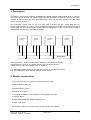
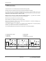
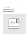
SIMADYN D
Digital Control System
User Manual
Memory module MM11
Edition 05.95
DK-Nr. 251141
User Manual, Memory module MM11
Edition
Edition status
1
Memory module MM11
03.91
2
Memory module MM11
05.95
Copying of this document and giving it to others and the use or
communication of the contents thereof is forbidden without express
authority. Offenders are liable to the payment of damages. All rights
are reserved in the event of the grant of a patent or the registration of
a utility model or design.
We have checked the contents of this Manual to ensure that they
coincide with the described hardware and software. However,
deviations cannot be completely ruled-out, so we cannot guarantee
complete conformance. However, the information in this document is
regularly checked and the necessary corrections included in
subsequent editions. We are thankful for any recommendations or
suggestions.
Contents
Contents
Warning information................................ ................................ ................................ ...................... 1
1. Description................................ ................................ ................................ ................................ 3
2. Module construction................................ ................................ ................................ .................. 3
3. Notes for the user................................ ................................ ................................ ...................... 4
4. Technical specification................................ ................................ ................................ .............. 4
5. STRUC L Menu in the master program ................................ ................................ ..................... 4
6. Appendices ................................ ................................ ................................ ............................... 5
6.1. Block diagram................................ ................................ ................................ ............ 5
6.2. Dimension drawing and table of connectors................................ ............................... 5
6.3. Location diagram ................................ ................................ ................................ ....... 5
7. ECB instructions................................ ................................ ................................ ........................ 6
Siemens AG Dk-Nr. 251141
SIMADYN D Hardware User Manual
Edition 05.95
Warning information
Edition 05.95
Siemens AG Dk-Nr. 251141
SIMADYN D Hardware User Manual
Warning information
NOTE!
The information in this Manual does not purport to cover all details or variations in equipment, nor to provide
for every possible contingency to be met in connection with installation, operation or maintenance.
Should further information be desired or should particular problems arise which are not covered sufficiently for
the purchaser’s purposes, please contact your local Siemens office.
Further, the contents of this Manual shall not become a part of or modify any prior or existing agreement,
committment or relationship. The sales contract contains the entire obligation of Siemens. The warranty
contained in the contract between the parties is the sole warranty of Siemens. Any statements contained
herein do not create new warranties nor modify the existing warranty.
Warning information
WARNING!
Electrical equipment has components which are at dangerous voltage levels.
If these instructions are not strictly adhered to, severe bodily injury and material
damage can result.
Only appropriately qualified personnel may work on this equipment or in its
vicinity.
This personnel must be completely knowledgeable about all the warnings and
service measures according to this User Manual.
The successful and safe operation of this equipment is dependent on proper
handling, installation, operation and maintenance.
Siemens AG Dk-Nr. 251141
SIMADYN D Hardware User Manual
Edition 05.95
1
Warning information
Definitions
*
QUALIFIED PERSONNEL
*
DANGER
*
WARNING
*
CAUTION
*
NOTE
For the purpose of this User Manual and product labels, a „Qualified person“ is someone who is familiar with the
installation, mounting, start-up and operation of the equipment and the hazards involved. He or she must have
the following qualifications:
1. Trained and authorized to energize, de-energize, clear, ground and tag circuits and equipment in accordance
with established safety procedures.
2. Trained in the proper care and use of protective equipment in accordance with established safety
procedures.
3. Trained in rendering first aid.
For the purpose of this User Manual and product labels, „Danger“ indicates death, severe personal injury and/or
substantial property damage will result if proper precautions are not taken.
For the purpose of this User Manual and product labels, „Warning“ indicates death, severe personal injury or
property damage can result if proper precautions are not taken.
For the purpose of this User Manual and product labels, „Caution“ indicates that minor personal injury or
material damage can result if proper precautions are not taken.
For the purpose of this User Manual, „Note“ indicates information about the product or the respective part of the
User Manual which is essential to highlight.
CAUTION!
This board contains components which can be destroyed by electrostatic
discharge. Prior to touching any electronics board, your body must be electrically
discharged. This can be simply done by touching a conductive, grounded object
immediately beforehand (e.g. bare metal cabinet components, socket protective
conductor contact).
WARNING!
Hazardous voltages are present in this electrical equipment during operation.
Non-observance of the safety instructions can result in severe personal injury or
property damage.
It is especially important that the warning information in all of the relevant
Operating Instructions are strictly observed.
2
Edition 05.95
Siemens AG Dk-Nr. 251141
SIMADYN D Hardware User Manual
Description
1. Description
The MM11 communications RAM is a SIMADYN D general purpose RAM module which is used for
data exchange via the local and communications busses. The MM11 enables the individual processor
modules to communicate with each other.Data transfer from one processor module to another takes
place in the following way:
One processor module bids for the bus and, after acquiring the bus, writes data into the
communications RAM. The node to which the data are addressed, must also bid for the bus and read
out the data from the communications RAM. Address management of the communications RAM is
automatically carried out by the operating system.
Prozessormodul 1
Koppelspeicher
Prozessormodul 2
..........
Prozessormodul 8
Bussystem
Either byte-wise or word-by-word access is possible. The RAM has a capacity
of 64K bytes for each bus. The address range for the local bus starts at
20000 H and for the communications bus at 30000 H.
Two terminating resistors, one for the local bus and one for the communications
bus, are integrated to obtain defined voltages on the busses.
2. Module construction
- Connections for local bus (X2) and communications bus (X1)
- 64K-byte RAM for each bus
- RAM access time 150 ns
- Data width 8 or 16 bits
- 3.4 V battery integrated in the subrack for saving data in the event
of a power failure
- Module identification with PAD equivalent circuit
- Module code: OAH
- Terminating resistor for communications bus and local bus integrated
Siemens AG Dk-Nr. 251141
SIMADYN D Hardware User Manual
Edition 05.95
3
Notes for the user
3. Notes for the user
The MM11 module already incorporates the necessary bus terminating resistors. A bus section cannot
take more than two bus terminators so that for each bus section only one external SR14 bus
terminator can be used in addition to the MM11.
The module must be fixed to the subrack using screws (even during commissioning) to ensure
trouble-free operation.
If the MM11 communications RAM is configured as an MM21 module (communications RAM for the
local bus only), the following changes must be made on the module:
- Remove the following:
R 16
(O ohms resistance)
D 22
(Pal 16L8)
Note: With these changes, the RAM components are decoupled from the communications bus whereas the integral bus terminator is still active.
When making these changes, make sure that the maximum permissible
load for a bus section including two bus terminators is not exceeded.
4. Technical specification
INSULATION GROUP
AMBIENT TEMPERATURE
STORAGE TEMPERATURE
HUMIDITY CLASS
ALTITUDE RATING
MECHANICAL STRESS
A to VDE 0110 paragraph 13, group 2 at 5V DC
0 to 55 deg. C
-40 to +70 deg. C
F to DIN 40040
S to DIN 40040
Installation in stationary equipment,
sensitive to vibrations
PACKAGING SYSTEM
DIMENSIONS
MODULE WIDTH
WEIGHT
ES 902 C
233.4 x 220 mm
1 1/3 SPS = 1 plug-in station = 20.14 mm
0.51 kg
CURRENT CONSUMPTION P5
- IN OPERATION
- POWER FAILURE
300 mA (typ.)
20 uA max. VBatt= 3.4 V
5. STRUC L Menu in the master program
:MM11
4
"mail box memory module, L+C-bus"
Edition 05.95
Siemens AG Dk-Nr. 251141
SIMADYN D Hardware User Manual
Appendices
6. Appendices
6.1. Block diagram
Block diagram
3GE 465 611 9003.00 SU
6.2. Dimension drawing and table of connectors
Dimension drawing, front plate and table of
connectors used
3GE 465 611 9003.00 MB
6.3. Location diagram
Location diagram
Siemens AG Dk-Nr. 251141
SIMADYN D Hardware User Manual
3GE 465 611 9003.00 A0
Edition 05.95
5
ECB instructions
7. ECB instructions
Components which can be destroyed by electrostatic discharge (ECB)
Generally, electronic boards should only be touched when absolutely necessary.
The human body must be electrically discharged before touching an electronic board. This can be
simply done by touching a conductive, grounded object directly beforehand (e.g. bare metal cubicle
components, socket outlet protective conductor contact.
Boards must not come into contact with highly-insulating materials - e.g. plastic foils, insulated
desktops, articles of clothing manufactured from man-made fibers.
Boards must only be placed on conductive surfaces.
When soldering, the soldering iron tip must be grounded.
Boards and components should only be stored and transported in conductive packaging (e.g.
metalized plastic boxes, metal containers).
If the packing material is not conductive, the boards must be wrapped with a conductive packing
material, e.g. conductive foam rubber or household aluminum foil.
The necessary ECB protective measures are clearly shown in the following diagram.
a = Conductive floor surface
b = ECB table
c = ECB shoes
Seated
6
d = ECB overall
e = ECB chain
f = Cubicle ground connection
Standing
Edition 05.95
Standing/sitting
Siemens AG Dk-Nr. 251141
SIMADYN D Hardware User Manual
ECB instructions
Siemens AG Dk-Nr. 251141
SIMADYN D Hardware User Manual
Edition 05.95
7
ECB instructions
Drives and Standard Products
Motors and Drives Systems Group
Postfach 3269, D-91050 Erlangen
8
System-Based
Technology
Edition 05.95
Siemens AG Dk-Nr. 251141
SIMADYN D Hardware User Manual