1
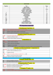
SIMADYN D
Digital Control System
User Manual
I/O board EM11
Edition 05.95
DK-Nr. 233141
User Manual, I/O board EM11
Edition
Edition status
1
I/O board EM11
03.91
2
I/O board EM11
05.95
Copying of this document and giving it to others and the use or
communication of the contents thereof is forbidden without express
authority. Offenders are liable to the payment of damages. All rights
are reserved in the event of the grant of a patent or the registration of
a utility model or design.
We have checked the contents of this Manual to ensure that they
coincide with the described hardware and software. However,
deviations cannot be completely ruled-out, so we cannot guarantee
complete conformance. However, the information in this document is
regularly checked and the necessary corrections included in
subsequent editions. We are thankful for any recommendations or
suggestions.
Contents
Contents
Warning information................................ ................................ ................................ .................... 1
1. Description................................ ................................ ................................ .............................. 3
1.1. New functions ................................ ................................ ................................ ..........4
1.1.1. RIC: *RDY-INTERNAL-CONTROL ................................ ............................ 4
1.1.2. Speed Value Inputs ................................ ................................ ...................4
1.1.3. Monitor Input of the Speed Value Connector................................ ..............5
1.1.4. Monitor Register for the Speed Value Input................................ ................5
1.1.5. Binary outputs................................ ................................ ............................ 6
1.1.6. Analog outputs................................ ................................ ........................... 6
2. Board Design ................................ ................................ ................................ .......................... 7
3. Application Notes ................................ ................................ ................................ .................... 8
4. Technical Specification ................................ ................................ ................................ ...........10
5. Connector Pin Assignments of the EM 11 ................................ ................................ ...............13
5.1. Pin Assignments for Actual Speed Value, Connector X5................................ ..........13
5.2. Pin Assignments of the Analog Inputs and Outputs, Connector X6........................... 13
5.3. Pin Assignments for the Binary Inputs/Outputs, Connector X7................................ .14
6. STRUC-L menu ................................ ................................ ................................ ...................... 15
7. Miscellaneous ................................ ................................ ................................ ......................... 16
7.1. Appendices................................ ................................ ................................ ..............16
7.1.1. Diagrams................................ ................................ ................................ ...16
7.1.2. Drawings ................................ ................................ ................................ ...18
8. ECB instructions................................ ................................ ................................ ...................... 19
Siemens AG Dk-Nr. 233141
SIMADYN D Hardware User Manual
Edition 05.95
Warning information
Edition 05.95
Siemens AG Dk-Nr. 233141
SIMADYN D Hardware User Manual
Warning information
NOTE!
The information in this Manual does not purport to cover all details or variations in equipment, nor to provide
for every possible contingency to be met in connection with installation, operation or maintenance.
Should further information be desired or should particular problems arise which are not covered sufficiently for
the purchaser’s purposes, please contact your local Siemens office.
Further, the contents of this Manual shall not become a part of or modify any prior or existing agreement,
committment or relationship. The sales contract contains the entire obligation of Siemens. The warranty
contained in the contract between the parties is the sole warranty of Siemens. Any statements contained
herein do not create new warranties nor modify the existing warranty.
Warning information
WARNING!
Electrical equipment has components which are at dangerous voltage levels.
If these instructions are not strictly adhered to, severe bodily injury and material
damage can result.
Only appropriately qualified personnel may work on this equipment or in its
vicinity.
This personnel must be completely knowledgeable about all the warnings and
service measures according to this User Manual.
The successful and safe operation of this equipment is dependent on proper
handling, installation, operation and maintenance.
Siemens AG Dk-Nr. 233141
SIMADYN D Hardware User Manual
Edition 05.95
1
Warning information
Definitions
*
QUALIFIED PERSONNEL
*
DANGER
*
WARNING
*
CAUTION
*
NOTE
For the purpose of this User Manual and product labels, a „Qualified person“ is someone who is familiar with the
installation, mounting, start-up and operation of the equipment and the hazards involved. He or she must have
the following qualifications:
1. Trained and authorized to energize, de-energize, clear, ground and tag circuits and equipment in accordance
with established safety procedures.
2. Trained in the proper care and use of protective equipment in accordance with established safety
procedures.
3. Trained in rendering first aid.
For the purpose of this User Manual and product labels, „Danger“ indicates death, severe personal injury and/or
substantial property damage will result if proper precautions are not taken.
For the purpose of this User Manual and product labels, „Warning“ indicates death, severe personal injury or
property damage can result if proper precautions are not taken.
For the purpose of this User Manual and product labels, „Caution“ indicates that minor personal injury or
material damage can result if proper precautions are not taken.
For the purpose of this User Manual, „Note“ indicates information about the product or the respective part of the
User Manual which is essential to highlight.
CAUTION!
This board contains components which can be destroyed by electrostatic
discharge. Prior to touching any electronics board, your body must be electrically
discharged. This can be simply done by touching a conductive, grounded object
immediately beforehand (e.g. bare metal cabinet components, socket protective
conductor contact).
WARNING!
Hazardous voltages are present in this electrical equipment during operation.
Non-observance of the safety instructions can result in severe personal injury or
property damage.
It is especially important that the warning information in all of the relevant
Operating Instructions are strictly observed.
2
Edition 05.95
Siemens AG Dk-Nr. 233141
SIMADYN D Hardware User Manual
Description
1. Description
The EM11 I/O board is used for digitizing (analog inputs with A/D or V/F/D converters) and for the
output of analog voltage signals, for the input of binary signals (speed), for input/output (binary I/O)
and display (LED) of binary information.
The programmable address decoder calculates the board address, related to the board location.
The board features the following:
a) X6: For digitizing analog voltage signals:
* Four channels with A/D conversion,
* Four channels with V/F and subsequent F/D conversion
(V/F/D conversion)
b) X6: For the output of analog voltage signals:
* Two channels with D/A conversion
c) X5: For incremental encoding:
* One channel for actual speed value and position encoding with
inputs for two tracks plus the zero marking pulse;
* Subsequent digital filter and quadrupling the track frequency of
the incremental shaft angle encoder
* One input for function monitoring
d) X7: For the input and output of binary information:
* 16 binary inputs and 8 binary outputs.
* 4 binary outputs for signal states of connector X5
e) H10/H20: For display:
* 16 LED's on the front panel, logical order in two bytes:
* one byte (H10) with red LED's (H11-H18, H11 is the least sign. bit)
* one byte (H20) with yellow LED's (H21-H28, H21 is the least sign. bit)
* independent from binary signals in d)
The 40 pin BERG connector X7 at the front panel is arranged in three rows of ten and one row of six
pins, whereas
* 10 pins are designed for 8-bit values,
external supply with P 24 external and M 24 external, and
* 6 pins are assigned to the zero marking pulse, track A signal,
Siemens AG Dk-Nr. 233141
SIMADYN D Hardware User Manual
Edition 05.95
3
Description
track B signal, monitor signal for connector X5, P 24 external and
M 24 external (the other 4 pins are not connected).
The connector is thus sub-divided into the following sections:
* 2 sections (bytes) for input,
* 1 section (byte) for output and
* 4 single bit output (1 bit information, wired and not configurable)
for the zero marking pulse, track A, track B and X5 monitor signal.
1.1. New functions
The board offers some additional features starting from version 3.0. It is compatible with former
versions, as long as the following is adhered to:
- The nominal levels of the speed value input (connector X5) are 15 V.
- The 5 V (supply for a shaft angle encoder) are no longer available at
pins 9 and 10 of the connector X5.
1.1.1. RIC: *RDY-INTERNAL-CONTROL
The new connector RIC in the board screen is designed to suppress the board reset signal *BGRES
when the *RDYIN signal occurs. An active signal *RDYIN usually generates a board reset *BGRES,
which causes the outputs (analog and binary: output of zero volts) to be disabled. The board requires
a renewed initialization. The RIC enables the board to continue running w i t h o u t *BGRES when
a processor fails in the sub-rack (*RDYIN active).
Filtering out this signal is only effective until the next *RESAD (reset signal from the power supply,
always generates a *BGRES).
If the *RDYIN is to be ineffective on the board, then a "Y" must be configured at the RIC connector
(i.e. the outputs remain active). The board does then not run a reset and the outputs remain enabled.
The default value of "N" in the STRUC-L screen corresponds to the functionality of the previous board
version.
1.1.2. Speed Value Inputs
The three tracks A, B and zero are detected via differential inputs with a rated voltage level of 15V.
The threshold lies by approximately half the rated level with a hysteresis of 5 to 15% of the rated level
(see technical specifications). The corresponding minus terminal of each track may be grounded
(ground supply terminal of the digital encoder from X5:M').
4
Edition 05.95
Siemens AG Dk-Nr. 233141
SIMADYN D Hardware User Manual
Description
1.1.3. Monitor Input of the Speed Value Connector
The supply of the speed plug connector with P5 is dispensed with because of the definition of the
speed signal level (5V - level deleted). The pins 9 and 10 have therefore become available for a
monitoring signal with a level of 15V. The threshold lies by approximately half the rated level with a
hysteresis of 5 to 15% of the rated level (see technical specifications).
The corresponding minus terminal of each track may be grounded (ground supply terminal of the
digital encoder from X5:M').
The speed input can be monitored with this monitoring input. Connection of a monitoring signal from
the digital speed encoder or checking whether the encoders plug is connected by jumpering P15' with
the positive input pin 9 and jumpering M' (ground) with the negative input pin 10.
1.1.4. Monitor Register for the Speed Value Input
The EM11 board has an additional monitor register starting from version3.0, which is accessed via
the ZPC connector.
Currently only bit 7 (X5_OK, status of monitoring input of X5) is utilized.
+---+---+---+---+---+---+---+---+
|7 |6 |5 |4 |3 |2 |1|0|
+---+---+---+---+---+---+---+---+
| | | | | | | |
| | | | | | | +--- irrelevant
| | | | | | |
| | | | | | +------- irrelevant
| | | | | |
| | | | | +----------- irrelevant
| | | | |
| | | | +--------------- irrelevant
| | | |
| | | +------------------- irrelevant
| | |
| | +----------------------- irrelevant
| |
| +--------------------------- irrelevant
|
+------------------------------- X5_OK, state of monitoring input of X5
This bit has the state HIGH, if the switching threshold of the monitor
input on speed value connector X5 is exceeded (see technical specification).
Otherwise it is LOW.
Siemens AG Dk-Nr. 233141
SIMADYN D Hardware User Manual
Edition 05.95
5
Description
1.1.5. Binary outputs
Three new binary outputs have been installed on previously unconnected pins of the sub-connector
X7B (pins 12, 13, 14, see also connector allocation).
These outputs permanently take the state of internal 5V signals. These are set via output drivers to a
24V level (usual binary output SIMADYN D, no reaction on the original signal). The signals are the
following:
X7, pin 11:
X7, pin 12:
X7, pin 13:
X7, pin 14:
zero marking pulse (as previous versions)
track A
track B
X5 monitor signal
1.1.6. Analog outputs
The two analog outputs of the board generate 0 V when disabled (in previous versions: -10V).
6
Edition 05.95
Siemens AG Dk-Nr. 233141
SIMADYN D Hardware User Manual
Board Design
2. Board Design
* One slot (1 1/3 SPS)
* SIMADYN D local bus interface
* Programmable address decoder with board identification
* Three system timing controllers AM 9513
* One analog/digital converter AD 574, 12 bits
* One digital/analog converter AD 7549, 12 bits
* Four analog input channels with multiplexer and A/D converter
* Four analog input channels with V/F/D conversion
* Two analog output channels with D/A converters.
* One channel for the incremental shaft angle encoder consisting of
the following:
* Three pulse inputs (2 tracks, 1 zero marking pulse), one monitor input
(differential amplifier inputs, non-floating)
* 16 binary inputs
(non-floating)
* 8 binary outputs
(non-floating, 30 V/ 50 mA max.)
* 1 binary output for zero marking pulse
(non-floating, 30 V/ 50 mA max.),
* 1 binary output for track A
(non-floating, 30 V/ 50 mA max.),
* 1 binary output for track B
(non-floating, 30 V/ 50 mA max.),
* 1 binary output for X5 monitor signal
(non-floating, 30 V/ 50 mA max.),
* 16 LED's on the front panel.
Siemens AG Dk-Nr. 233141
SIMADYN D Hardware User Manual
Edition 05.95
7
Application Notes
3. Application Notes
The EM 11 board can be used in all SIMADYN D sub-racks connected to the local bus. It requires one
slot in the sub-rack.
The board must be fixed to the sub-rack with screws (even during commissioning) to ensure perfect
operation.
If the board is plugged onto an adapter, the front panel (or better still one of the two metallized front
panel handles) must be electrically connected to chassis via a short lead.
The pulse inputs at connector X5 are linked with the incremental shaft angle encoder of the drive via
a multi-core screened cable.
The appropriate block diagram is shown in the appendix, diagram 1.
Supplementary Components at the Speed Input:
Component set
* SM1.1
6 DD 1680 - 0AB1
15 pin male connector, with casing
The analog input and output signal lines are connected via the SE7.1 interface module, which snaps
onto the mounting rail. The 20 pin ribbon cable SC12 is used to inter-connect boards from connector
X6 to the interface module connector X1. The cable type SC12 (twisted pair) guarantees higher
transmission security.
The SE7.1 interface module provides one screw-type terminal each for signal inputs ± ,signal
outputs/ground and screen for each channel.
The SE40 interface modules enable additional boards to be connected (1-to-1 connection between
faston connectors and screw-type terminals).
The configuration for analog signals is shown in the appendix in diagram 2.
Supplementary components used for analog signals:
Ribbon cable
* 20 pole, twisted pair, 1.5 m SC12
6 DD 1684 - 0BC0,
* 20 pole
6 DD 1684 - 0BB0.
2.0 m SC11
Interface modules
* SE7.1
6 DD 1681 - 0AH1
I/O block, analog, 8/10 channels
* SE40
6 DD 1681 - 0EA0
terminal block, 20 pole, one to one
8
Edition 05.95
Siemens AG Dk-Nr. 233141
SIMADYN D Hardware User Manual
Application Notes
The binary signal lines are connected as follows:
Ribbon cables are used to link connector X7 of the EM11 board with the interface modules (both ends
are provided with ribbon cable socket connectors).
The corresponding block diagram is located in the appendix, as diagram 3.
The binary outputs are supplied with power (24V) via the interface modules.
The M24 ground is simultaneously reference potential for the binary inputs and is connected to the
SIMADYN D ground on the board.
Comments to diagram 3:
to a)
The 16 binary inputs and outputs at connector X7 of the EM11
are connected to the SE3.1 or SE23 interface module via a 40 pin
ribbon cable. The interface modules incorporate the external
connections for the plant (screw-type terminals).
to b)
The binary inputs and outputs of the connector are split up and
allocated to four different SE4.1 interface modules. The 40 pin
connector is divided up into four separate cables by splitting
up the attached ribbon cable (4 x 10 pin, with sub-connector
identification, see diagram 3) at the ends and connecting
the four cable sections to the individual interface modules.
Thus it is possible e.g. to connect input or output signal lines
with or without galvanic isolation.
Supplementary binary input and output components
Ribbon cable
* 40 pin
2.0 m
SC18
6DD 1684-0BJ0
* 40 pin --> 4+10 pin
2.0 m
SC13
6DD 1684-0BD0
Siemens AG Dk-Nr. 233141
SIMADYN D Hardware User Manual
Edition 05.95
9
Technical Specification
Interface modules
* SE3.1 6DD 1681-0AD0
16 binary inputs and 16 binary outputs, non-floating
* SE4.1 6DD 1681-0AE1
8 binary inputs or outputs, non-floating
* SE5.3 6DD 1681-0AF3
8 binary inputs, 220 V, floating
* SE6.1 6DD 1681-0AG1
8 binary outputs, 220 V max., floating
* SE8
6DD 1681-0AJ0
8 binary inputs or outputs
(10 pin, one-to-one connection)
* SE23
6DD 1681-0CD0
16 binary inputs and 16 binary outputs
(40 pin, one-to-one connection)
* SE37
6DD 1681-0DH0
8 binary outputs, 24 V, floating
* SE41.1 6DD 1681-0EB1
8 binary inputs, 48 V, floating
* SE41.2 6DD 1681-0EB2
8 binary inputs, 24 V, floating
4. Technical Specification
GENERAL
INSULATION COORDINATION
AMBIENT TEMPERATURE
STORAGE TEMPERATURE
PROTECTION TYPE
HUMIDITY CLASS
ALTITUDE RATING
MECHANICAL STRESS
PACKAGING SYSTEM
DIMENSIONS
BOARD WIDTH
WEIGHT
CURRENT CONSUMPTION
acc. to VDE 0110/1.89;contamination grade 2
0 to 55 deg. C, with unforced ventilation
-40 to +70 deg. C
IP00 acc. to DIN 40050
F to DIN 40040
S to DIN 40040
Installation in stationary, equipment,
sensitive to vibrations
ES 902 C
233.4 x 220 mm
1 1/3 SPS = 1 slot = 20.14 mm
0.6 kg
P5 1.20 A
P15 0.10 A + Consumption connector X5, P15'
N15 0.15 A + Consumption connector X5, N15'
P24 0.10 A + Consumption connector X7A, X7B
BINARY INPUTS
NUMBER
INPUT VOLTAGE
FOR 0 SIGNAL
FOR 1 SIGNAL
INPUT CURRENT
10
16, no galvanic isolation
+24 V rated value
-1V to +6V; or binary inputs open
+13 V to +33 V
Edition 05.95
Siemens AG Dk-Nr. 233141
SIMADYN D Hardware User Manual
Technical Specification
- AT 1 SIGNAL
DELAY
BINARY OUTPUTS
NUMBER
SUPPLY VOLTAGE
- RIPPLE
- PERM. RANGE
- TEMPORARY
OUTPUT CURRENT AT 1 SIGNAL
- PERM. RANGE
SHORT-CIRCUIT PROTECTION
TO GROUND
DELAY
INDUCTIVE CIRCUIT INTERRUPT.
TOTAL LOAD
RESIDUAL CURRENT
SIGNAL LEVEL
- AT 0 SIGNAL
- AT 1 SIGNAL
5 mA (typical)
200 us
12, no galvanic isolation
24 V - rated value
3.6 V DC
+20 to +30 V, including ripple
+35 V, t < 0,5 sec.
50 mA rated value
O.2 mA to 60 mA
Electronic, unlimited duration
15 us at full load
4 us at no load (measurement instrument)
Limited to -1V
80 % at 55 deg. C all outputs 50 mA
20 uA at 0 signal
24 VDC rated
3 V max.
-2.5 V min. supply voltage
ANALOG OUTPUTS D/A CONVERSION
NUMBER
OUTPUT VOLTAGE (MIN.)
OUTPUT VOLTAGE (MAX.)
OUTPUT CURRENT (MAX.)
RESOLUTION
ACCURACY (ABSOLUTE / TYPICAL)
SHORT-CIRCUIT PROTECTION
TO GROUND
SHORT-CIRCUIT DURATION (MAX.)
TOTAL LOAD
2
- 10 V
+ 10 V
10 mA
11 bits + sign (corresponding to 5 mV)
± 0.25 % ( = ± 25 mV)
Ohmic resistance 56 Ohm
120 sec
All outputs simultaneously at 10 mA each
MEASURING SYSTEMS
ANALOG INPUTS WITH A/D CONVERSION
NUMBER
4
RATED INPUT VOLTAGE (MIN.)
- 10V
RATED INPUT VOLTAGE (MAX.)
+ 10V
OVERLOAD INPUT VOLTAGE (MIN.)
- 14 V (absolute value)
OVERLOAD INPUT VOLTAGE (MAX.)
+ 14 V (absolute value)
INPUT RESISTANCE
20 kohms (differential amplifier input)
RESOLUTION
11 bits + sign (corresponding to 5 mV)
ACCURACY (ABSOLUTE / TYPICAL)
± 0.25 % ( = ± 25 mV)
ANALOG WITH V/F/D CONVERSION
NUMBER
RATED INPUT VOLTAGE (MIN.)
RATED INPUT VOLTAGE (MAX.)
OVERLOAD INPUT VOLTAGE (MIN.)
OVERLOAD INPUT VOLTAGE (MAX.)
INPUT RESISTANCE
RESOLUTION
ACCURACY (ABSOLUTE / TYPICAL)
Siemens AG Dk-Nr. 233141
SIMADYN D Hardware User Manual
4
- 10V
+ 10V
- 14 V (absolute value)
+ 14 V (absolute value)
20 kohms (differential amplifier input)
14 bits + sign (corresponding to 0.6 mV)
± 0.25 % ( = ± 25 mV)
Edition 05.95
11
Technical Specification
ACTUAL SPEED VALUE ACQUISITION
PULSE INPUTS TRACKS ZERO, A, B,
AND MONITOR INPUT
PULSE AMPLITUDE
PULSE FREQUENCY (MAX.)
SIGNAL LEVEL
1-SIGNAL
0-SIGNAL
SWITCHING HYSTERESIS
SMOOTHING TRACKS ZERO, A, B
SMOOTHING MONITOR INPUT
POWER SUPPLY
P15'
M'
N15'
SHORT CIRCUIT PROTECTION (GRD)
SHORT CIRCUIT DURATION (MAX.)
15 V, 1 mA rated value
8-30 V, I maximum = 3 mA
100 KHz sin or squarewave sampling 1:1
7,5 V rated value for threshold
>8V
< 5 V, minimum: -30V
>1V
1 usec
200 usec
P15', M', N15', each via resistance
+15 V ± 10%, Imax = 250mA, Ri = 3,6Ohm
0 V ± 0,2V, Imax = 250mA, Ri = 0,9Ohm
-15 V ± 10%, Imax = 250mA, Ri = 3,6Ohm
Resistance (Ri)
1 sec., longer: Ri becomes infinite
NOTE : SPECIAL ATTENTION MUST BE PAID TO THE TOTAL LOADING OF THE
SUB-RACK POWER SUPPLY WHEN THE SUPPLY OUTPUTS AT PLUG
CONNECTOR X5 IS LOADED (CONCERNS P15', N15'). THIS IS
ESPECIALLY IMPORTANT WHEN SEVERAL EM11 BOARDS ARE SUPPLIED
FROM ONE SUB-RACK POWER SUPPLY. THE SIMADYN-D POWER SUPPLY
CUTS OUT WHEN OVERLOADS OCCUR (I.E. ALSO FOR SHORT CIRCUITS).
The practical resolution of the measuring systems depends on the function blocks used.
Measuring system
Function block
--------------------------------------------------------------------------A/D conversion
ADC001 : analog input
V/F/D conversion
AFC001 : analog frequency/digital conversion
D/A conversion
DAM
: analog output EM 11
Actual speed value acquisition
NAV
: digital actual speed value
acquisition
12
Edition 05.95
Siemens AG Dk-Nr. 233141
SIMADYN D Hardware User Manual
Connector Pin Assignments of the EM 11
5. Connector Pin Assignments of the EM 11
5.1. Pin Assignments for Actual Speed Value, Connector X5
Socket
no.
1
2
Designation
Connector Function
Screen
Digital ground
3
4
NC
Zero marking pulse Z+
X5A, B
5
6
Track A+
Track A-
X5A, B
X5A, B
7
P15'
8
Digital ground
9
10
11
Monitor +
Monitor Zero marking pulse Z-
X5A,B
12
13
Track B+
Track B-
X5A,B
X5A,B
14
N15'
15
Screen
Voltage reference for
P15' or P5'
Not connected
Connection for zero
marking pulse
Connection for track A
Inverse signal or zero
voltage reference for
track A
Supply voltage for
encoder +15 V
Zero voltage reference
for P15' or P5'
Monitor signal
Monitor signal, reference
Inverse signal or zero
voltage reference point
for zero marking pulse
Connection for track B
Inverse signal or zero
voltage reference point
for track B
Supply voltage for
encoder -15V
5.2. Pin Assignments of the Analog Inputs and Outputs, Connector X6
Pin
no.
1
2
3
4
5
6
7
8
9
10
11
12
13
14
15
16
17
18
19
20
Designation
Connector
Analog input 1+
Analog input 1Analog input 2+
Analog input 2Analog input 3+
Analog input 3Analog input 4+
Analog input 4Input (V/F) 1+
Input (V/F) 1Input (V/F) 2+
Input (V/F) 2Input (V/F) 3+
Input (V/F) 3Input (V/F) 4+
Input (V/F) 4Analog output 1
Analog ground
Analog output 2
Analog ground
X6A
Siemens AG Dk-Nr. 233141
SIMADYN D Hardware User Manual
X6B
X6C
Function
4 analog inputs with
differential amplifiers
and one A/D converter
(multiplexed)
X6D
X6E
X6F
X6G
4 analog inputs with
differential amplifiers
V/F converters and F/D
conversion
X6H
X6J
X6K
D/A conv., analog signal
reference for output 1
D/A conv., analog signal
reference for output 2
Edition 05.95
13
Connector Pin Assignments of the EM 11
The two analog outputs can only be addressed via function block DAM.
5.3. Pin Assignments for the Binary Inputs/Outputs, Connector X7
(40 pin faston connector)
Pin
no.
1
2
3
4
5
6
7
8
9
10
11
12
13
14
15
16
17
18
19
20
21
22
23
24
25
26
27
28
29
30
31
32
33
34
35
36
37
38
39
40
14
Designation
Connector
Output 1
Output 2
Output 3
Output 4
Output 5
Output 6
Output 7
Output 8
P external
M external
Output 9
Output 10
Output 11
Output 12
N.C.
N.C.
N.C.
N.C.
P external
M external
Input 1
Input 2
Input 3
Input 4
Input 5
Input 6
Input 7
Input 8
P external
M external
Input 9
Input 10
Input 11
Input 12
Input 13
Input 14
Input 15
Input 16
P external
M external
X7 A
X7 A
X7 A
X7 A
X7 A
X7 A
X7 A
X7 A
X7 B
X7 B
X7 B
X7 B
Function
Binary outputs
External power supply for binary
inputs and outputs
Output for zero marking pulse
Not connected
External power supply for binary
inputs and outputs
X7 C
X7 C
X7 C
X7 C
X7 C
X7 C
X7 C
X7 C
Binary inputs
External power supply for binary
inputs and outputs
X7 D
X7 D
X7 D
X7 D
X7 D
X7 D
X7 D
X7 D
Binary inputs
External power supply for binary
inputs and outputs
Edition 05.95
Siemens AG Dk-Nr. 233141
SIMADYN D Hardware User Manual
STRUC-L menu
6. STRUC-L menu
: EM11
ISE 1C = N
ZPC 8K <
X5A 4K <
X5B 4K <
X6A 1K <
X6B 1K <
X6C 1K <
X6D 1K <
X6E 1K <
X6F 1K <
X6G 1K <
X6H 1K <
X7C 8K <
X7D 8K <
X6J 1K >
X6K 1K >
X7A 8K >
H10 8K >
H20 8K >
"I/O board mixed, L-bus"
"Ignore failed message (RDYINT) (Y/N) ?"
"Zero impulse monitor register"
"actual position"
"digital speed"
"A/D converter 1"
"A/D converter 2"
"A/D converter 3"
"A/D converter 4"
"V/F/D converter 1"
"V/F/D converter 2"
"V/F/D converter 3"
"V/F/D converter 4"
"binary inputs 1"
"binary inputs 2"
"D/A converter 1"
"D/A converter 2"
"binary outputs 1"
"LED block 1: H11-H18"
"LED block 2: H21-H28"
Siemens AG Dk-Nr. 233141
SIMADYN D Hardware User Manual
Edition 05.95
15
Miscellaneous
7. Miscellaneous
7.1. Appendices
7.1.1. Diagrams
a)
EM11
-X5
Kabeltyp: SC18
type of cable: SC18
40
-X6
-X7
-X1
Externe Anschlüsse
external connections
b)
EM11
-X5
Kabeltyp: SC13
type of cable: SC13
40
-X6
-X7
10
1
10
10
10
1 A
11 B
21 C
31 D
-X1
-X1
-X1
-X1
Externe Anschlüsse
Diagram 1
16
Edition 05.95
Siemens AG Dk-Nr. 233141
SIMADYN D Hardware User Manual
Miscellaneous
type of cable: SC12 (twisted pair)
EM11
20
-X5
-X6
-X7
-X1
external connections
Diagram 2
Teilesatz SM1.1
set SM1.1
EM11
Kabeltyp: geschirmt, mehradrig nach Bedarf
type of cable: shielded, n-way as needed
n
-X5
-X6
-X7
Anschluss Impulsgeber
connection incremental encoder
Diagram 3
Siemens AG Dk-Nr. 233141
SIMADYN D Hardware User Manual
Edition 05.95
17
Miscellaneous
7.1.2. Drawings
Block diagram
Block diagram
page 1 and 2
3GE.465 640.9002.01 SU
Dimension drawing and table of connectors
Dimension drawing showing front panel and table
of connectors used:
3GE.465.640.9002.01 MB
Location diagram
Location diagram
18
3GE.465.640.9002.01 AO
Edition 05.95
Siemens AG Dk-Nr. 233141
SIMADYN D Hardware User Manual
ECB instructions
8. ECB instructions
Components which can be destroyed by electrostatic discharge (ECB)
Generally, electronic boards should only be touched when absolutely necessary.
The human body must be electrically discharged before touching an electronic board. This can be
simply done by touching a conductive, grounded object directly beforehand (e.g. bare metal cubicle
components, socket outlet protective conductor contact.
Boards must not come into contact with highly-insulating materials - e.g. plastic foils, insulated
desktops, articles of clothing manufactured from man-made fibers.
Boards must only be placed on conductive surfaces.
When soldering, the soldering iron tip must be grounded.
Boards and components should only be stored and transported in conductive packaging (e.g.
metalized plastic boxes, metal containers).
If the packing material is not conductive, the boards must be wrapped with a conductive packing
material, e.g. conductive foam rubber or household aluminum foil.
The necessary ECB protective measures are clearly shown in the following diagram.
a = Conductive floor surface
b = ECB table
c = ECB shoes
Seated
Siemens AG Dk-Nr. 233141
SIMADYN D Hardware User Manual
d = ECB overall
e = ECB chain
f = Cubicle ground connection
Standing
Edition 05.95
Standing/sitting
19
ECB instructions
20
Edition 05.95
Siemens AG Dk-Nr. 233141
SIMADYN D Hardware User Manual
ECB instructions
Drives and Standard Products
Motors and Drives Systems Group
Postfach 3269, D-91050 Erlangen
Siemens AG Dk-Nr. 233141
SIMADYN D Hardware User Manual
System-Based
Technology
Edition 05.95
21