1
TECHNICAL HELPLINE 01684 774000
e
d
f
g
m
a
c
h
b
i
l
k
j
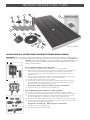
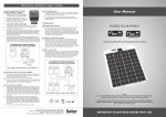
Kit shown: STPMH080
PLEASE READ ALL INSTRUCTIONS CAREFULLY BEFORE WORK BEGINS
IMPORTANT: When connecting a solar panel to a battery, it is always recommended that a voltage regulator is used to
prevent both reverse current feed (at night) and overcharging of the battery. The only exception to this is the STP005 and
STP010 because they are fitted with a reverse feed diode and if connected to battery size
at or greater than 35Ah and 70Ah respectively will not overcharge because of each
1A
B
battery’s own impedance.
Step 1: Fitting the cable to the solar panel
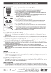
1.1 Remove the cover (A) from the terminal box on the rear of the Solar Panel
A
1.2 Panel sizes up to 28wp generally have the junction box style shown in Fig 1A. Panels 43wp
and over have the syle shown in Fig 1B. Fitting the cable to both is similar but with the
3 terminal style shown in Fig 1B you should ignore the centre terminal (L/H terminal is –ve
and R/H is +ve).
1.3 Take one end of the cable and strip back the black outer insulation 4.5cm. Strip back the
insulation of the red and black inner cables 1.5cm to expose bare wire.
1.4 Feed the cable through the hole in the terminal box.
1B
C
1.5 Twist the bare wire ends tightly and wrap clockwise around the loosened terminal screws
B or C (depending which junction box style you have). Alternatively, two ring terminals
(supplied) can be crimped onto the bare cable ends.
Red (positive), black (negative) as marked on inside of terminal box
1.6 Tighten terminal screws and replace the terminal box cover.
Step 2: Fitting the in-line connector to cable (optional)
This connector is supplied as a convenient means of desconnecting the panel from battery.
2.1 Decide where in te cable you would like to locate the in-line plug and socket. Cut the cable.
2
2.2 Strip back the black outer insulation of the cable connedted to the solar panel 2cm. Strip
back the insulation of the red and black inner cables 0.5cm to expose bare wire.
2.3 Remove the cover male plug (D) and remove the cover. Loosen the two terminal screws (E).
2.4 Twist the bare wire ends tightly and feed through the hole on the plug. Fit each wire end into
the correct terminal and tighten the clamp screw:
Red (positiv) = terminal 1 (E);
Black (negative) = terminal 2 (E)
2.5 Tighten terminal screws and replace cover.
2.6 Repeat precedure for the female socket (F)