1
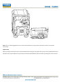
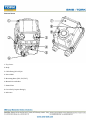
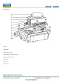
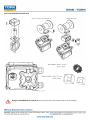
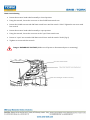
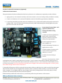
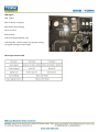
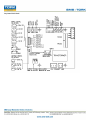
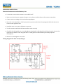
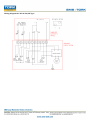
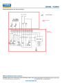
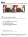
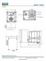
SMS Sanayi Malzemeleri ve Satısı A.S. REA 60 Electric Actuator Manual CONTENT INTRODUCTION PRODUCT IDENTIFICATION GENERAL INFORMATION AND FEATURES INSTALLATION INSTRUCTION ACTUATOR MOUNTING DETAILS OPERATION INSTRUCTION MAINTENANCE TROUBLE SHOOTING DIMENSION FOR ACTUATOR INTRODUCTION This installation and operating manual explains how to install, operate and maintain REA60 electric actuators. Safety notices in this manual detail precautions the user must take to reduce the risk of personal injury and damage to the equipment. User must read these instructions before installation, operating, or maintenance. DANGER: Refers to personal safety. Alerts the user to potential danger or harm. The hazard or unsafe practice will result in severe injury or death. WARNING: Refers to personal safety. Alerts the user to potential danger. Failure to follow warning notices could result in personal injury or death. CAUTION: Directs the user’s attention to general precautions that, if not followed could result in personal injury and/or equipment damage. PRODUCT IDENTIFICATION The actuator name plate is located on the top cover of the actuator. The name plate contains the following: TORK logo (trade mark) Electrical power supply Model Type Rated current Operating time (seconds) Serial No. Option Initial Inspection Upon receipt of the actuator, inspect the condition of the product and ensure the name plate matches the order sheet or your requirements, also check for any damage that may have occurred during shipment. If the wrong product has been shipped immediately or is damaged report to the coordinator. Storage Actuators must be stored in a clean, cool and dry area. The unit shall be stored with the cover fastened and the conduit openings sealed. Storage must be off the floor, covered with a seal dust protector. When actuators are stored outdoors, they must be stored off the ground, high enough to prevent being immersed in water or buried in snow. GENERAL INFORMATION AND FEATURES REA series electric actuators are designed to provide reliable and efficient operation of 90 degree quarter turn valves , dampers, etc. Performance Max Output Torque MODEL REA-60 Nm 60 Operating Time(sn) Duty Cycle 50/60Hz S4(%) 110V 90° 12/14 70% 0,39/0,4 Nominal Current(A) 60/50Hz AC Capacitor(uF) 220V Capacitor(uF) 5 0,2/0,19 1,2 DC 24V Weight Kg 0,2 3 Handwheel Turn N 8 Mounting Size ISO5211 F03,F04,F05 Technical Data Enclosure Rated Weatherproof IP67 Enclosure High grade aluminium alloy, corrosion coated Power Supply 110/220 VAC 1 Ph, 24 VAC - 24VDC 50/60Hz Motor Reversible motor Limit Switches 2 x open/close SPDT, 250 VAC 10A rating Auxiliary Limit Switches 2 x open/close SPDT, 250 VAC 10A rating Indicator Continuous position indicator Manual Manual Override Nut Space Heater 2W Conduit Entries 2 x PG 13.5 Lubrication Grease moly EP Ambient Temperature -20ºC ̴ + 70ºC External Coating Dry powder polyester REA Option Technical Data PIU Potentiometer unit (0 ̴ 1K Ω) PCU Proportional control unit (input, output 0 ̴10 VDC or 4 ̴20mA DC) CPT Current position transmitter (output 4 ̴ 20mA DC) Duty Cycle Duty cycle is rated IEC60034 - S4 50% / S2 30 min Exceeding the actuators rated duty cycle may cause thermal overload. Type of duty according to VDE 0530 / IEC 60034-1 Short - time duty S2 The operation time at a constant load is short, so that ther-mal equilibrium is not reached. The pause is long enough for the machine to cool down to ambient temperature. The duration of the short - time operation is limited to 15 min (10 min, 30 min). Intermittent duty S4 The duty is a sequence of identical cycles which consist of starting time, operation time with constant load and rest period. The rest period allows the machine to cool down so that so that thermal equilibrium is not reached. The relative on-time at S4-25% or S4-50% is limited to 25% and 50% respectively . Heater Condensation in the actuator is possible due to wide fluctuation of the ambient temperature. The heater integrated in the control unit prevents this in general. Manual Hand Wheel and Lever REA actuators are provided with a manual operation system. The REA60 actuator comes standard with a manual override nut. This is located on the bottom of the unit, and can be easily operated with a 5M wrench. Turn the hand wheel until the valve reaches the required position. Turn clockwise to open and counter clockwise to close. When nut becomes tight DO NOT FORCE further as this will cause serious damage to the gearing. Note: The override engagement lever returns automatically to auto position when the actuator is operated electrically. Lubrication REA is a totally enclosed unit with a permanently lubricated gear train (Moly EP Grease). Once installed lubrication should not be required. However, periodic preventative maintenance will extend the operating life of the actuator. External Parts 1. Top Cover 2. Body 3. Cable Entry(PG 13.5)x2 4. Drive Shaft 5. Mounting Base (F03, F05, F07) 6. Manual Override Nut 7. Name Plate 8. Cover Bolt (Captive Design) 9. Indicator Internal Parts 1. Motor 2. Indicator 3. Open limit switch 4. Additional open limit switch 5. Potentiometer Unit 6. Terminal 7. Heater 8. Capacitor INSTALLATION INSTRUCTION Pre-Installation (for use in General Services) Verify the actuators name plate to ensure correct model number, force, operating speed, voltage and enclosure type before installation and use. It is important to verify that the output force of the actuator is appropriate for the force requirements of the valve and that the actuator duty cycle is appropriate for the intended application. WARNING: Read this installation and maintenance manual carefully and completely before attempting to install, operate or trouble shoot the REA actuators. Actuator Mounting Note: Prior to mounting the part-turn actuator it must be checked for damage. Damaged parts must be replaced by original spare parts. Mounting is most effectively carried out with the valve shafting pointing vertically upwards, however mounting is also possible in any other position. The REA series actuators are supplied with a Union Joint and nut which is removable for ease of machining. CAUTION: Do not attempt to work on your REA actuator without first shutting off Incoming power. Do not attach ropes or hooks to the hand wheel for the purpose of lifting by hoist. ACTUATOR MOUNTING DETAILS Danger: HAZARDOUS VOLTAGE (Make sure all power is disconnected prior to mounting) Limit Switch Setting Rotate the actuator hand wheel manually to closed position Using hex wrench, loosen the set screw on the CLOSE limit switch cam Rotate the CLOSE cam towards CW limit switch lever until the switch “clicks” Tighten the set screw with hex wrench Rotate the actuator hand wheel manually to open position Using hex wrench, loosen the set screw in the “open” limit switch cam Rotate to “open” cam towards CCW limit switch lever until the switch “clicks” (fig 2) Tighten set screw with hex wrench Danger: HAZARDOUS VOLTAGE (Make sure all power is disconnected prior to mounting) Position Feedback Potentiometer (Optional) Calibration Potentiometer The potentiometer has been calibrated at the factory, however if re-calibration is required proceed as follows: Apply power (or use manual override) to drive the actuator to its true closed position (clockwise rotation) Connect an ohmmeter to P1 (red) and P3 (black) resistance should be approximately 1000ohms Loosen the point shaft gear and connect the ohmmeter to P1 (red) and P2 (white) and gently rotate until a reading of 80 - 120 Ω is achieved (100 ohms preferred). While maintaining this reading tighten the point gear set screw with a hex wrench. Proportional Control Unit - PCU (Optional/REA Series) Check point before using actuator 1. Check specification (Model No., Main Power, Control Power, Options) of delivered actuator meets your requirements. 2. Check application such as valve, damper etc. 3. Check mounting of actuator on application is correct. 4. Check setting of actuator such as limit switch, stopper bolts, indicator, is correct. 5. Check electrical wiring is correct. 6. In case of 3 phase motor, check rotating direction. *Check rotating direction of actuator, “open” actuator about 50% by manual, supply power to actuator for 2-3 seconds. Push close button and check if actuator moves to “close” direction. If this actuator moves to “close” it is correct. To reverse the motor stop the power supply to the actuator and change the 2 of the 3 power lines which changes the direction of the motor. 7. Generally all functions of PCU is set by the factory before delivery and there is no need to set the functions again. The functions should only be changed if the customer wishes to adjust the limit switches, to set the function the PCU is required. To set simply push the “Auto Setting” button after putting actuator in the 50% open (or close) position. PCU automatically sets all the functions by itself . 8. Disassembly modification without factory consent may affect the performance of the actuator. Before installing or operating the actuator, please read this manual to lean how to install and operate. The contents of this manual are subject to change due to quality improvement without individual notice. General Performance PCU is the local actuator controller, using 12 bit A/D converter and 8 bits Microprocessor which operate the actuator to open and close according to the signal from the main controller. After operating actuator it detects the current position of the actuator and transmits a feedback output signal advising of the current position to the main controller . Standard Specification Model: PCU REV 3.1 Model: 85V ̴ 280 VAC ± 10% 50/60Hz 4VA Max (New wide range of voltage) Input Signal: 4 ̴20mA DC, 2 ̴ 10VDC, 0 ̴ 5VDC, 0 ̴ 10VDC, 1 ̴ 5VDC Input resistance: 250 Ohm Feedback Signal: 100 ̴ 10 Kohm Extraction: 2.3 VDC Output Signal: 4 ̴20mA DC, 2 ̴ 10VDC, 0 ̴ 5VDC, 0 ̴ 10VDC, 1 ̴ 5VDC Load Resistance: 750ohm Max. Control Output: Relay contact 250VAC 10A Max (Inductive load) Number of Output Contact: 2 ea (Open and Close contact) Delay Time Adjustment: 0 ̴ 7.5 sec (1 Step 0.5 sec 0 - 15 Step) Dead Band Adjustment: 0.1 ̴ 4.5% Resolution: Min 1/1000 Position Conversation Accuracy: ±1.5% (Depends on installation) Ambient Temperature: -10ºC ̴ +70ºC Ambient Humidity: 90% RH Max (Non-condensate) Dielectric Strength: 1500V AC 1 Min (Input to Output, Power to Ground) Insulation Resistance: Min 500VDC 30Mohm Vibration & Shock (X, Y, Z): 6g based on RMF, Frequency: 0.2 ̴ 34Hz, 30 min LED Signal LED Signal Blue on Power on (Auto) Blue Flicker Auto Setting Green on Close Red on Open Yellow on Manual OPN.by card Yellow Flicker Fault in either wrong input wiring, wrong PIU setting No input signal Check Operation of PCU Lay Out of PCU Card OPERATION INSTRUCTION Electrical Connections and Preliminary Test Loosen the screws on the actuator cover and lift it off Make sure that the power supply voltage is in accordance with the data on the actuator name plate Connect wires according to the enclosed wiring diagram Move the valve manually to a half-open position, operate and electrical opening and check that the motor rotates in the right direction Standard units are counter-clockwise to open set Test the actuator and check the limit switches work correctly Check all the cable glands are correctly tightened, applicable cable glands should be selected to be meet the applications condition. Over the grade IP67 of cable gland recommended in potentially explosive atmospheres. Mount cover and tighten cover bolts Wiring Diagram for 230V AC On/Off Type Wiring Diagram for 230V AC PCU Type Wiring Diagram for 24VAC On/Off Type Wiring Diagram for 24V DC On/Off Type MAINTENANCE Caution: Turn off all power services before attempting to perform a service on the actuator. POTENTIAL HIGH PRESSURE VESSEL. Before removing or disassembling the actuator ensure the valve or other actuated devices are isolated and not under pressure. Maintenance under normal conditions at six month intervals, however when conditions are more severe, more frequent inspections may be advisable. Ensure valve actuator alignment Ensure wiring is insulated, connected and terminated properly Ensure all screws are present and tight Ensure cleanliness of internal electrical devices Ensure conduit connections are installed properly and are dry Check internal devices for condensation Check power to internal heater Check enclosure O-ring seals and verify the O-ring is not pinched between flange Verify declutch mechanism Visually inspect during open /close cycle Inspect identification labels for ware and replace if necessary Warning: Treat cover with care. Gap surfaces must not be damaged or dirtied in any way. Do not jam cover during fitting. Tools 1 Metric Allen Key (Hex Wrench) 1 Screw Driver 1 Metric Spanner 1 Wrench 200mm 1 Wrench 300mm 1 Wire Stripper Long Nose 1 Multi Meter (AC, DC, Resistance) 1 DC Signal Generator (4 -̴ 20mA): PCU Board Option 1mA Meter (0 ̴25mA): PCU Board Option TROUBLE SHOOTING The following instructions are offered for the most common difficulties encountered during installation and start up. Actuator does not respond Verify the line voltage to the actuator Check that the voltage matches the rating on the actuator nameplate Check internal wiring against actuator wiring diagram Check limit switch cams Actuator is receiving power but does not operate Verify the line voltage to the actuator Check actuator force to see if it’s greater than the valve force Check limit switches and cams Check that the force switches have not tripped Check mechanical travel stop adjustment Verify the actuator against valve rotation (standard units are anti-clockwise open) Check internal wiring Check for corrosion and condensation Verify coupler/bracket are correctly installed and is not causing binding Actuator runs erratically Check ambient temperature Verify that the duty cycle has not been exceeded Check the position of manual override lever Optional Equipment Potentiometer Current Position Transmitter Check resistance value Check potentiometer gear for jamming Check zero and span calibration Check board for damage DIMENSION FOR ACTUATOR On/Off Type PCU Type