1
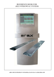
USER MANUAL FOR
AREX DIGI+ SYSTEMS
Arex Test Systems bv, Vennestraat 4b, 2161 LE Lisse, Holland
Property of:
Arex Test Systems bv
Vennestraat 4b
2161 LE Lisse
Tel:
+31 (0) 252 419151
Fax:
+31 (0) 252 420510
E-mail: [email protected]
The contents of this manual are subject to change without notice. All efforts have been made to ensure
the accuracy of this manual. However, should any errors be detected, AREX would greatly appreciate
being informed of them. The above not withstanding, AREX can assume no responsibility for any errors
in this manual or their consequences.
Date:
Software version:
15 nov 2010
V27
USER MANUAL AREX DIGI+ SYSTEMS
1
TABLE OF CONTENTS
CHAPTER 1
DESCRIPTION OF THE AREX DIGI+ SYSTEM .......................................................... 3
1.1 The AREX DIGI+ Brake Tester ..................................................................................................... 3
1.2 The AREX DIGI+ Side Slip Meter.................................................................................................. 3
CHAPTER 2
INTRODUCTION INTO THE OPERATION OF THE AREX DIGI+ SYSTEM ............... 4
CHAPTER 3
THE AREX DIGI+ BRAKE TESTER ............................................................................. 5
3.1 A brake test on a 2-plate version ................................................................................................... 5
3.2 A brake test on a 4-plate version ................................................................................................... 6
3.3 Entering the vehicle weight ........................................................................................................... 7
3.4 Printing the test results .................................................................................................................. 8
3.5 Interpretation of test results ........................................................................................................... 8
3.5.1 Brake force.............................................................................................................................. 8
3.5.2 Deceleration rate / brake efficiency ........................................................................................ 8
3.5.3 Imbalance left to right per axle................................................................................................ 9
3.6 Sending the test data..................................................................................................................... 9
CHAPTER 4
THE SIDE SLIP METER .......................................................................................... 10
4.1 Carrying out a side slip test ......................................................................................................... 10
4.2 The automatic side slip test ......................................................................................................... 10
4.3 The interpretation of sideslip results ............................................................................................ 10
CHAPTER 5
MAINTENANCE .......................................................................................................... 11
5.1 Maintenance of the display and accessories .............................................................................. 11
5.2 Maintenance to the Floor Items ................................................................................................... 11
5.3 Periodic Maintenance .................................................................................................................. 11
CHAPTER 6 TECHNICAL SPECIFICATIONS..................................................................................... 12
USER MANUAL AREX DIGI+ SYSTEMS
2
CHAPTER 1
DESCRIPTION OF THE AREX DIGI+ SYSTEM
The AREX DIGI+ System is available in four versions:
2P
2PS
4P
4PS
2-plate Brake Tester
2-plate Brake Tester with Side Slip Meter
4-plate Brake Tester
4-plate Brake Tester with Side Slip Meter
All above mentioned systems are a combination of floor items connected to a processor unit with digital
display mounted on a frame. Infra red remote control, A4 printer with printer shelf is optional.
Following is a short description of the Brake Tester and the Side Slip Meter.
1.1 The AREX DIGI+ Brake Tester
The AREX DIGI+ Brake Tester consists of two or four brake plates, which are mounted either in or on
the floor. Each plate registers the brake force of the wheel that is braked on it. The brake plate consists
of a sub frame and a top plate with needle bearings between them to minimize friction. The top plate has
an expanded metal surface to create a good friction contact. A force transducer measuring the brake
force is mounted between the top plate and the sub frame. A signal cable connects the force transducer
to the processor unit and the display will show the results.
1.2 The AREX DIGI+ Side Slip Meter
The AREX DIGI+ Side Slip Meter consists of two movable top plates, mounted on a sub frame. The top
plates move on needle bearings. The Side Slip Meter measures sideslip per axle. If the wheels on the
axle are not aligned correctly, the measuring plate (the largest of the two) is pushed sideways. The
sideways movement is measured by a shift potentiometer, which sends a signal to the processor unit
through a signal cable; the display shows the result. The smaller of the two movable top plates serves to
compensate for any lateral forces within the tire/wheel ensuring very accurate readings.
USER MANUAL AREX DIGI+ SYSTEMS
3
CHAPTER 2
INTRODUCTION INTO THE OPERATION OF THE AREX DIGI+ SYSTEM
The AREX DIGI+ System contains an automatic testing mode. This means you do not need to actually
operate the system.
The use of the remote control is optional. The remote control is particularly useful for entering the
vehicle weight (also see 3.3 Entering the vehicle weight) and for printing the test results (also see 3.4
Printing the test results).
Furthermore, it is possible to leave the automatic mode and manually choose a particular test.
Underneath is an overview of the various keys on the remote control and their function:
KEY
0
1
2
3
4
5
6
7
8
9
C
E
FUNCTION
Show deceleration
Service brake front axle (2P)
Service brake rear axle (2P)
Service brake (4P)
Parking brake
Printing
Entering the vehicle weight
Side slip front axle
Side slip rear axle
Send test data
Repeat, change, cancel
Enter, continue
USER MANUAL AREX DIGI+ SYSTEMS
4
CHAPTER 3
THE AREX DIGI+ BRAKE TESTER
This chapter describes how to perform a brake test on the AREX DIGI+ Brake Tester.
A brake test on a 2-plate installation is described in paragraph 3.1.
The 4-plate brake test is described in paragraph 3.2.
3.1 A brake test on a 2-plate version
On a 2-plate Brake Analyser the service brake is tested in two runs: one for the front axle, one for the
rear axle.
The 2-plate brake test can be carried out in automatic as well as in manual mode. The following steps
describe an automatic test of service brake front axle, service brake rear axle and parking brake.
►
At the start of the automatic brake test, the display shows a number of horizontal lines. The
front axle of the vehicle drawn on the display shows a flashing red light, indicating the system
is ready to test the front axle. Before driving onto the plates, note this:
1. It is recommended to firmly apply the braking pedal a couple of times, just before carrying out
the actual brake test. This is to ensure the brakes function at all and to do away with possible
condensation.
2. Place the vehicle in line with the brake plates. make sure the distance to plates allows you to
accelerate up to +/- 10 km/h.
3. Make sure there are no people and/or object standing close to the brake plates.
►
Drive up onto the brake plates with a speed of +/- 10 km/h. Apply the brake pedal as soon as
the front axle hits the friction surface of the brake plates. Try and progress the pedal force
gradually, using the full length of the plates. Avoid applying the brake pedal too abruptly.
►
After the vehicle has come to a standstill at the far end of the brake plates, the front axle
results appear on the screen. The display shows the maximum brake force measured left and
right together with the imbalance left to right. The results remain on the display for 10 seconds.
►
Drive off the brake plates backwards within 10 seconds and place the vehicle in line with the
plates again.
►
The display now shows a red light in the rear axle of the vehicle drawn on the display. Follow
the same procedure as for the front axle, but now apply the brake pedal when the rear axle
hits the friction surface of the brake plates. After the test, the rear axle results remain on the
display for 10 seconds.
USER MANUAL AREX DIGI+ SYSTEMS
5
►
Drive off the brake plates backwards within 10 seconds and place the vehicle in line with the
plates again.
►
The display shows a red light in the parking brake of the vehicle drawn on the display. Follow
the same procedure as for the front and rear axle, but now apply the parking brake when the
parking brake axle hits the friction surface of the brake plates. After the test, the screen shows
the parking brake results during 10 seconds.
►
After completion of the whole test, the system reverts back to the beginning of the automatic
test procedure and is ready to test the next vehicle.
3.2 A brake test on a 4-plate version
On a 4-plate Brake Analyser the service brake is tested in one go; front and rear axle at the same time.
Apart from the time-saving aspect, this test has a number of other advantages in comparison to a test
on a 2-plate version; the front axle and rear axle are tested with the same pedal force and can therefore
be related to each other and the brake force distribution between front and rear is shown.
The 4-plate brake test can be carried out in automatic as well as in manual mode. An automatic brake
test for service brake and parking brake is carried out as follows:
►
At the start of the automatic brake test, the display shows a number of horizontal lines. The
front and rear axle of the vehicle drawn on the display show a flashing red light, indicating the
system is ready to test the service brake. Before driving onto the plates, note this:
1. It is recommended to firmly apply the braking pedal a couple of times, just before carrying out
the actual brake test. This is to ensure the brakes function at all and to do away with possible
condensation.
2. Place the vehicle in line with the brake plates. make sure the distance to plates allows you to
accelerate up to +/- 10 km/h.
3. Make sure there are no people and/or object standing close to the brake plates.
USER MANUAL AREX DIGI+ SYSTEMS
6
►
Drive up onto the brake plates with a speed of +/- 10 km/h. Apply the brake pedal as soon as
the front axle hits the friction surface of the front axle brake plates. Try and progress the pedal
force gradually, using the full length of the plates. Avoid applying the brake pedal too abruptly.
►
After the vehicle has come to a standstill at the far end of the brake plates, the front axle
results appear on the screen. The display shows the maximum brake force measured left and
right together with the imbalance left to right. The display toggles between the front and rear
axle results. The red light indicates to which axle the results refer.
►
Drive off the brake plates backwards within 10 seconds and place the vehicle in line with the
plates again.
►
The display shows a red light in the parking brake of the vehicle drawn on the display. Follow
the same procedure as for the front and rear axle, but now apply the parking brake when the
parking brake axle hits the friction surface of the brake plates. After the test, the screen shows
the parking brake results.
►
After completion of the whole test, the system reverts back to the beginning of the automatic
test procedure and is ready to test the next vehicle.
3.3 Entering the vehicle weight
You can enter the vehicle weight with the remote control (option).
Push key 6; the display will show a number of zeros. Key in the weight and enter it by pushing E. The
system uses the vehicle weight to calculate the deceleration rate / brake efficiency. The weight and
deceleration rate / brake efficiency will appear on the print out (see 3.4 Printing the test results).
USER MANUAL AREX DIGI+ SYSTEMS
7
3.4 Printing the test results
You can print the test results on the printer (option) using the remote control (option).
Push key 5; the results of the last test will be printed.
3.5 Interpretation of test results
The following results are important:
•
brake force.
•
deceleration / brake efficiency.
•
imbalance left/right per axle.
3.5.1 Brake force
The AREX DIGI+ Brake Tester measures the forces that the wheels exert on the brake plates while the
vehicle is braking. Each individual brake force shown is taken at the point during the test when the total
brake force on the axle is the maximum value.
The total brake force of the service brake is the sum of all the four brake forces. The total brake force of
the parking brake is the sum of the brake forces of the parking brake, measured on the left and right
wheel.
3.5.2 Deceleration rate / brake efficiency
The AREX DIGI+ Brake Tester determines the deceleration rate as follows:
deceleration rate = total brake force/vehicle weight
Example:
total brake force
vehicle weight
deceleration rate
= 6000 Newton
= 1000 kilograms
= 6000/1000 = 6.0 m/s2
Deceleration can also be expressed as a percentage of gravital acceleration (9.8 m/s2). This is obtained
by dividing the total brake force in kilograms by the vehicle weight in kilograms x 100%.
When the test is done and the weight has been entered, the deceleration can be shown on the display
by using key 0. The left display shows the deceleration of the service brake and the right display shows
the deceleration of the parking brake. The deceleration can be shown in m/s² or in %.
The deceleration is shown underlined on the print-out, when it is under the legally required deceleration.
USER MANUAL AREX DIGI+ SYSTEMS
8
3.5.3 Imbalance left to right per axle
After each brake test the AREX DIGI+ Brake Tester gives the imbalance between the maximum brake
force measured on the left and the maximum brake force measured on the right wheel of each axle. The
imbalance is expressed as a percentage of the higher of the two brake forces.
The imbalance is shown underlined on the print-out, when the maximum difference for that axle is
exceeded.
3.6 Sending the test data
You can send the test data of the vehicle with the remote control (option). For this function you need; a
serial cable and the DigiComm program on a PC.
When all the data of the vehicle have been assembled the data is sent automatically, or by pushing key
9, to the PC where the DigiComm program is running. The data is shown in the DigiComm program in
numerical and graphical layout and can be printed to a standard A4 printer.
After entry of the weight, the data which changes because of this is once again sent.
USER MANUAL AREX DIGI+ SYSTEMS
9
CHAPTER 4
THE SIDE SLIP METER
This chapter describes how to perform a sideslip meter test on the AREX DIGI+ Side Slip Meter.
The Side Slip Meter can be installed at two different places.
•
•
Between the brake plates (4-plate system).
In front of the brake plates (2-plate system).
In both cases the side slip can be measured when driving onto the brake tester.
4.1 Carrying out a side slip test
The most reliable sideslip readings are obtained if the body and suspension are at rest. Any imposed
sideways movement of the wheels due to bumping of the car or steering action will influence the
measurement.
Position the wheel in front of and in line with the sideslip meter. Drive up slowly and make sure the
steering wheel is in the neutral position. Declutch before passing across the sideslip meter plate and do
not move the steering wheel.
4.2 The automatic side slip test
Where the sideslip test is carried out whilst driving up for the brake test it is, of course, impossible to
drive slowly. Also keeping the car body and wheel suspension at rest is difficult. Testing sideslip in this
way may lead to less reliable results and it is recommended that you carry out the side slip test
separately.
4.3 The interpretation of sideslip results
In order to ensure good road holding, the wheels of a vehicle must be aligned correctly. Badly aligned
wheels cause the tires to wear rapidly. Toe, camber and caster must be adjusted according to
specifications supplied by the manufacturer of the vehicle. Toe, which is the number one tire wear angle,
is often expressed in millimetres (inches) of deviation from the longitudinal axis of the vehicle.
It is important to distinguish between 'static' toe and 'running' toe. The ideal toe setting to aim for,
regardless of the type of vehicle, is always zero 'running' toe. This does not mean, however, that the
'static' toe must be adjusted to zero.
Sideslip is dynamic phenomenon, which can only be measured whilst moving. The Arex Side Slip Meter
measures the sideways movement of the wheels as they pass across the measuring plate. The
maximum displacement is expressed in meters per kilometre (feet per mile). This relates to the running
'toe'.
USER MANUAL AREX DIGI+ SYSTEMS
10
CHAPTER 5
MAINTENANCE
The AREX DIGI+ System is very maintenance friendly. Nevertheless, it is important to closely follow the
instructions below.
5.1 Maintenance of the display and accessories
Before carrying out any maintenance to the system make sure the computer and/or accessories are
disconnected from the main electrical supply.
When necessary, the display housing and panel can be cleaned with a soft, clean cloth dampened with
a mild detergent, dissolved in water. Do not allow the water to penetrate into the housing. The printer
can be cleaned using a dry, clean and soft cloth.
When you need to change the printer ribbon, these can be ordered from your AREX supplier.
Any other maintenance should only be carried out by a trained AREX engineer.
5.2 Maintenance to the Floor Items
The floor plates can be cleaned by an occasional brushing with a broom. It is strongly recommended not
to use air or water underneath the plates. This could damage the bearings.
Avoid using aggressive detergents.
This can also damage the bearings and even the force transducers.
Never try to lift or move the plate.
Any other maintenance should only be carried out by a trained AREX engineer.
5.3 Periodic Maintenance
For periodic maintenance, calibration and service contact your AREX supplier/installer.
USER MANUAL AREX DIGI+ SYSTEMS
11
CHAPTER 6 TECHNICAL SPECIFICATIONS
Plate brake tester:
System 5520/BD1700
Dimensions of brake plate:
1500 X 620 X 35 mm
Material:
6 mm dip galvanised steel
Number of brake plates:
2 or 4
Measuring principle:
Force transducer with strain gauges
Measuring range:
0 – 10.000 Newton
Resolution:
15 Newton
Maximum roll over weight:
2500 kg per wheel
Installation:
On or in floor
Side Slip meter:
Dimensions 740 X 60 X 35 mm
Material:
6 mm dip galvanised steel
Measuring principle:
Linear potentiometer
Measuring range:
- 9 m/km tot + 9 m/km
Resolution:
1 m/km
Maximum roll over weight:
2500 kg per wheel
Installation:
On or in floor
Display:
5520/BD1700
Dimensions of brake display and frame:
1550 X 540 X 110 mm
Dimensions sideslip display
240 X 540 X 110 mm
Power:
1 phase, 240 V 100 W
Optional Accessories:
IR remote control, printer, printer shelf
USER MANUAL AREX DIGI+ SYSTEMS
12