1
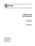
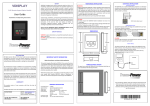
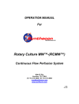
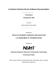
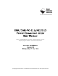
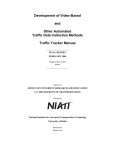
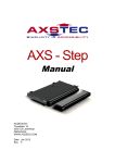
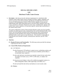
CONTROLLER INTERFACE DEVICE (CID) II
FINAL REPORT
NOVEMBER 2001
Budget Number KLK201
N01-24
Prepared for
OFFICE OF UNIVERSITY RESEARCH AND EDUCATION
U.S. DEPARTMENT OF TRANSPORTATION
Prepared by
NATIONAL INSTITUTE FOR ADVANCED TRANSPORTATION TECHNOLOGY
UNIVERSITY OF IDAHO
Brian Johnson, Richard Wells, Michael Kyte, Darcy Bullock, Zhen Li, Ying Zhou, James Richards, John Fisher, Jeremiah
Remus, Cody Miller, Eugene Bordenkircher, Richard Duldulao, Thomas Jacob, Dan Gordon, Matt Lee
TABLE OF CONTENTS
EXECUTIVE SUMMARY ...................................................................................................... 1
DESCRIPTION OF PROBLEM............................................................................................... 2
Hardware-in-the-Loop Simulation Concept ......................................................................... 3
Application of Microscopic Simulation Technology............................................................ 5
Programmable Suitcase Tester.............................................................................................. 5
APPROACH AND METHODOLOGY ................................................................................... 7
Project Time Line ................................................................................................................. 7
Breadboard Prototype, Spring 1999.................................................................................. 7
Laboratory Prototype, Summer 1999................................................................................ 7
Production Prototype ........................................................................................................ 8
Design Feedback................................................................................................................... 9
Beta Testing ........................................................................................................................ 10
Technology Transfer........................................................................................................... 11
Publications......................................................................................................................... 11
Next Generation CID II ...................................................................................................... 12
Next Generation Design.................................................................................................. 13
CID II Description .............................................................................................................. 14
Mechanical Design.......................................................................................................... 14
Firmware Design............................................................................................................. 17
Application Software ...................................................................................................... 20
CID Design Team ............................................................................................................... 27
Controller Interface Device (CID) II
i
EXECUTIVE SUMMARY
The CID (Controller Interface Device) II developed by the National Institute for Advanced
Transportation Technology (NIATT) is a bridge between the host personal computer running
a software application and the traffic controller. Upon request from the CID application
software running on a PC, the CID transfers data from the PC to the traffic controller through
the traffic controller inputs. When the traffic controller responds to the data received, the
resulting control signals are transferred back to the software application on the PC.
NIATT’s CID II provides a real-time interface between a 170, 2070 and NEMA TS1 and
TS2 traffic controllers and application software on a personal computer or laptop running
Windows 98, Windows ME or Windows 2000.
Data is transferred between the PC and the CID over a Universal Serial Bus (USB) cable.
The data transfer between the CID and the traffic controller travels over cables connecting to
the traffic controller cable harness. The CID is able to connect to 64 inputs and 64 outputs on
the traffic controller.
Current software applications are
1. A real-time interface between the TSIS/CORSIM traffic simulation running on a
computer and 170, 2070 and NEMA TS1 and TS2 traffic controllers (hardware-inthe-loop simulation). The simulation runs with the real traffic controller instead of a
generic model in the simulation, resulting in more realistic simulations that can be
used to test traffic signal plans or train new engineers.
2. A suitcase tester, in which a laptop computer and a CID are used to test the settings of
a traffic controller and simulate full operation of the controller. This allows signal
timing and progression to be checked under multiple scenarios prior to field
installation.
3. A hardware tester that can be used to test the operation of the CID periodically and
test the continuity in the cables connecting the CID to the traffic controller.
Controller Interface Device (CID) II
1
DESCRIPTION OF PROBLEM
Two parallel research paths have been followed in recent years for developing advanced
traffic signal systems. Real-time traffic adaptive system research has been supported largely
by the U.S. Department of Transportation (DOT), while smaller scale closed loop systems
have been developed primarily by traffic signal system vendors. Simulation models have
been developed for evaluating DOT supported projects. However, even though there are
several hundred traffic responsive systems now deployed, most of the vendor-developed
closed loop signal systems have not undergone such rigorous evaluations. This is an area of
significant concern because deployment of efficient closed loop signal systems is one of the
most cost effective Intelligent Transportation System (ITS) investments that a small urban
area can make. In order to make good deployment decisions, rational quantitative evaluation
procedures are required to evaluate feasible alternatives.
A common feature of all of these systems is that they use some type of vehicle detection and
change the display of signal indications according to some prescribed logic that is designed
to optimize certain system measures of effectiveness (MOEs). However, virtually all of the
signal systems in commercial production implement their control logic on unique computing
platforms. Furthermore, the algorithms are usually considered proprietary and are generally
not available to the traffic engineering community for conducting a rigorous scientific
evaluation.
At the same time, computing power has reached the point where microscopic network
simulations of an entire network are now feasible. Several microscopic simulation packages
are available that model vehicle movement and basic coordinated-actuated signal logic.
However, because of the proprietary nature of the various traffic responsive and traffic
adaptive algorithms, there is no generally available package that can be used for either
quantitatively evaluating the performance of alternative algorithms, or to serve as a design
tool for “tuning” system parameters prior to deployment.
Controller Interface Device (CID) II
2
As a result, the only studies agencies have available to assist in their design and decisionmaking process are vague “before-after” studies conducted with probe vehicles or system
detectors. Many of these studies use the old system with outdated signal timing schemes as
the “before” case, so it is unclear if the benefits are simply associated with the new timings or
the new traffic responsive or traffic adaptive system. Furthermore, because of the natural
stochastic variation of traffic and huge costs associated with systematically collecting system
performance data, few if any of the studies present rigorous statistical comparisons.
Hardware-in-the-Loop Simulation Concept
There are several efforts in the United States to integrate microscopic simulation programs
with traffic signal control hardware to study the performance of vendor specific algorithms.
Figure 1 depicts the typical hardware-in-the-loop simulation architecture for a NEMA closed
loop traffic signal. There are three basic components:
•
A controller interface device (CID). This device provides the interface from the
traffic controller to the computer running a microscopic simulation. The interface is
typically based upon the discrete voltage levels used to drive the load switches and
monitor loop detectors.
•
A software interface module to provide the linkage between the CID and a
microscopic simulation program. Since the software runs under Windows, this
software interface is typically implemented in a dynamic link library (DLL) software
module.
•
A microscopic simulation engine responsible for moving vehicles through a defined
network and tabulating MOEs. The simulation engine does not implement any control
logic. Instead, external signal state indications (RED, AMBER, and GREEN) are
obtained from actual traffic signal control equipment connected to the simulation
computer. The traffic signal control equipment is “stimulated” by detector calls
placed by the simulation program via the CID.
Controller Interface Device (CID) II
3
Since all control equipment ultimately controls load switches and monitors detector calls, the
discrete signal interface is the lowest common denominator interface that all controllers must
have. Consequently, this architecture provides a common evaluation framework to which a
variety of signal control systems can be connected for conducting scientifically rigorous and
reproducible evaluations. Although not shown in Fig. 1, a typical simulation would have each
controller connected to either a closed loop master or a central control system running an
64
CORSIM
USB
USB
Traffic
USB
CID 1
64
Controller 1
64
USB
Traffic
CID 2
64
Controller 2
64
USB
Traffic
CID3
64
Controller 3
64
USB
Traffic
CID 40
64
Controller
Figure 1 NIATT CID II system topology.
Controller Interface Device (CID) II
4
algorithm such as RHODES, UTCS, SCOOT, SCATS or other emerging real-time control
procedures.
Application of Microscopic Simulation Technology
In order to make the evaluation system shown schematically in Fig. 1 useful for evaluating
alternative control algorithms, it is essential that the CIDs be interfaced with a robust
microscopic simulation program. The microscopic simulation is responsible for “moving” all
vehicles through a user-defined network following prescribed vehicle kinematics. Simulation
of traffic movement is performed by recalculating the position of each vehicle at a
deterministic frequency, typically between 1 and 10 Hz. During each recalculation, vehicle
accelerations in the simulation are updated in response to signal indications obtained from
the CID and adjacent vehicles in the network. Appropriate detectors states are also updated
by way of the CID during each simulation interval. To ensure that the occupancy calculated
by the traffic controllers closely models field conditions, the duration of the presence
detectors is inversely proportional to the velocity of the vehicle actuating the detector. This
imposes a rather severe timing constraint that is addressed in the NIATT CID by delegating
the timing of the detector presence times to the CID. This conserves scarce USB bandwidth
and eliminates the problems with real-time scheduling of tasks running on Windows 95, 98,
NT or 2000.
Programmable Suitcase Tester
Traditional suitcase testers are essentially boxes containing switches that actuate functions on
the controller and monitor outputs of the controller via light emitting diodes (LEDs). The
suitcase tester provides a controlled environment for verifying that the controller behaves as
expected when particular features are programmed. The CID facilitates the development of a
PC-based programmable suitcase tester. Instead of mechanically opening and closing
switches, the suitcase tester software application simulates switches and LEDs. However, the
Controller Interface Device (CID) II
5
software application can be programmed to implement functions that the traditional suitcase
tester cannot implement.
A programmable suitcase tester provides the ability to automate testing of traffic controllers,
allowing technicians to more thoroughly and consistently test a set of controllers. The
software application can be set to represent different types of detector calls. The testing can
be optimized for the type of controller or for a specific application by changing software
settings.
The configuration shown in Fig. 1 is modified slightly for the suitcase tester application.
Probably the most common setup will be a computer interfacing to a single traffic controller
through the CID. However, the USB connection between each CID and the application
computer also allows testing of several traffic controllers in parallel or even studying
coordination between several different traffic controllers.
Controller Interface Device (CID) II
6
APPROACH AND METHODOLOGY
Project Time Line
A three-step process was followed in the design and testing of the CID. First a breadboard
prototype was constructed; then a laboratory prototype and finally a production prototype
were constructed.
Breadboard Prototype, Spring 1999
The basic system architecture was specified, including specifications for the USB
communication, microcontroller and firmware requirements. A senior design team of
students in electrical and computer engineering built a breadboard prototype to test the basic
architecture using a microcontroller development system board. At the same time, the basic
software requirements were specified for the TSIS/CORSIM application.
Laboratory Prototype, Summer 1999
The next benchmark on the design was the development of two laboratory prototypes.
Electrical engineering students designed custom printed circuit boards for the microcontroller
board, the display board and the input/output board. A mechanical engineering student
designed a compact enclosure for the CID. The laboratory prototypes were demonstrated at
the 69th Annual ITE Conference in Las Vegas, Nevada, in August 1999. Discussions
commenced with representatives of McCain Traffic Supply about possible licensing of the
CID design.
Several design problems were identified during the design and testing of the laboratory
prototypes:
•
Design for assembly
•
Design for reliable operation
•
Design for manufacturability
•
Cost reduction
Controller Interface Device (CID) II
7
Resolution of these issues became a focus in the subsequent production prototype stage. Note
that most university research stops after completing the laboratory prototype stage.
Production Prototype
The objective of the next stage of the project was to develop a production prototype that
could be transferred to an industrial partner with minimal redesign needed on their part.
The mechanical architecture was changed, with the objective of producing a design that
would be less expensive, easier to assemble and would use more standard parts for ease of
manufacture. A motherboard/daughterboard design was implemented to help resolve the
assembly issues. This design also reduces electrical noise by eliminating most of the internal
cable runs. The motherboard is used to interconnect the microcontroller board with two input
boards, two output boards, a display board and a power supply board.
Software development continued, with the TSIS/CORSIM application completed, and two
additional applications were developed: a suitcase tester (to test the traffic controller) and a
hardware tester (to test the CID).
Limitations with the Microsoft Windows 98 USB driver were also examined. The chief
concern with the device driver was to ensure that, when the simulation time step would be
decreased from its current time step of one second to 100 milliseconds as planned, the driver
would be able to concurrently run 40 CIDs with TSIS/CORSIM.
Designing the hardware and microcontroller firmware to meet production standards was a
major element of the production prototype design phase. Another problem faced was that the
Intel microcontroller used in the laboratory prototype was discontinued during the production
prototype stage. As a result, eight “pre-production” prototypes were built to test the other
aspects of the prototype design while a final production prototype was developed using a new
microcontroller. This testing did identify the need for a number minor design changes that
were subsequently incorporated in the production prototypes.
Controller Interface Device (CID) II
8
The use of the motherboard/daughterboard design minimized the impact of the change in
microcontrollers. Only the microcontroller board needed to be redesigned; none of the other
boards were affected by the change. The redesign in the microcontroller board also provided
the opportunity to add additional features to the CID II, including an RS-485 transceiver that
allows a relatively simple modification of the CID to incorporate the serial communication
link to the 2070 and NEMA TS2 traffic controllers.
More detail in the design of the CID II and a description of the software applications is
presented in the Appendix.
Design Feedback
The CID II design team used a number of avenues to generate feedback to improve the
design. The NIATT Center for Traffic Operations Peer Review Panel was a significant
source of feedback in the early stages of the project. The peer review panel met with the CID
II team early in the production prototype stage, and they heard presentations detailing the
design issues and concepts developed up to that time. A number of good suggestions for
design modifications came out of the meeting and were incorporated into the design. Several
members of the Peer Review Panel were contacted over the course of the year to help design
team members understand issues and problems the CID II needed to address.
McCain Traffic Supply was identified as a potential partner to commercialize the CID II
design, and negotiations led to a license agreement and subsequent transfer of the production
prototype design. Two review meetings were held with engineers from McCain. These
meetings proved to be a valuable source of feedback and led to several changes in the design
of the CID II so that it would better fit McCain’s manufacturing process. In addition, the
students working on the design had support from engineers and technicians at McCain. This
support not only facilitated the design of CID, but also provided the students with an insight
into the design of commercial hardware. McCain also provided assistance with fabricating
Controller Interface Device (CID) II
9
cases for the prototypes, assembling cable harnesses, and suggesting PC board fabrication
houses.
The pre-production prototypes were demonstrated at the 70th Institute of Transportation
Engineers Annual Meeting in Nashville. The response was positive and a number of requests
for beta units were received, along with inquiries about when the commercial versions will
be available.
Beta Testing
An initial beta test was conducting in August 2000, when seven CIDs were used as part of
the Traffic Signal Summer Camp held by NIATT on the University of Idaho campus. The
last day of the camp involved use of the CIDs with NEMA TS1 controllers, including a
TSIS/CORSIM simulation with three CIDs running concurrently. The CIDs performed well
at the camp. This was repeated during NIATT’s Traffic Signal Summer Camp II in August
2001 when six CIDS were used to interface traffic controllers to TSIS/CORSIM simulation.
Twelve CIDs were sent out for beta testing in late fall 2000. Beta testers included
government agencies such as the City of Portland, the Ada County Highway District, the
Florida DOT, and the Idaho Transportation Department. Other beta testers included
consulting firms, traffic signal manufacturers and Darcy Bullock of Purdue University and
Roelof Engelbrecht of Texas A&M University, experts on hardware-in-the-loop simulation.
Feedback from the beta test was largely used to test and modify the software applications and
improve the User’s Manual. In addition, comments from the beta testers led to several
modifications to the CID firmware. The beta test is largely over, but four of the beta testers
agreed to conduct a second round of testing on the application software.
Controller Interface Device (CID) II
10
Technology Transfer
The University of Idaho and NIATT signed a license agreement with McCain Traffic Supply
to manufacturer and market the CID II. The first production run is expected to be completed
in early 2002. A product unveiling is scheduled for the annual Transportation Research
Board meeting in January 2002.
Publications
Professor Brian Johnson and Professor Michael Kyte organized a special session on RealTime Simulation of Traffic Systems of the IEEE Industrial Electronics Society Annual
Meeting (IECON’01) scheduled for Denver, Colorado, at the end of November 2001. Six
papers were presented at the session, including a paper describing the CID II and a paper
describing the use of the CID II at the Traffic Signal Summer Camp. A paper describing the
CID II and related software applications has also been submitted to Transportation Research,
Part C. The paper is currently out for review.
Controller Interface Device (CID) II
11
FINDINGS; CONCLUSIONS; RECOMMENDATIONS
The production prototype phase of the CID II was completed, as well as, beta testing. An
industrial partner was identified to license the design. The CID II project appears to nearing a
successful completion.
In addition, there were more requests for beta test units than were available. The CID II has
been specified for use in a FHWA-sponsored project to test traffic controller settings on
several hundred new traffic controllers. Parties involved with that project have provided
valuable suggestions for possible improvements to the CID II design and for features to add
to the application software.
Next Generation CID II
Several upgrades to the CID are currently in the design. Two of the more immediate concerns
are:
•
Addition of RS 485 serial data line communication (SDLC) interface to allow the
CID to communicate with NEMA TS2 type 1, NEMA TS2 type 2 and 2070
controllers. The design changes will involve modifications to the case design and
changes in the firmware for the microcontroller. A more significant change is
required to fully implement the capabilities of the SDLC capabilities described in the
TS2 standard. This could possibly be available as an add-on to purchasers of the
initial CID.
•
Resolution of the Windows USB driver issues. The USB driver shipped with
Windows 98 and Windows 2000 is geared toward bulk transfer applications such as
keyboards, mice and other cases where precise timing is not critical. The isochronous
transfer mode support in the driver although weak, is adequate for the CID. However,
some changes in the application software or possibly to the driver could improve
performance.
Controller Interface Device (CID) II
12
Next Generation Design
Preliminary studies have also commenced to explore options for a next generation CID to
improve capabilities and shrink the package further. The present version of CID has two
input boards and two output boards to support the 64 input-outputs. One objective of this
project is to study the feasibility of implementing the input/output logic onto a programmable
logic device (PLD) while at the same time increasing the number of inputs and outputs
supported. A custom IC (ASIC) would also be a possibility rather than a PLD, but the sales
volume for CIDs will probably not justify the expense. The PLD supports hundreds of
inputs/outputs in a single IC about the size of a microprocessor. With this implementation,
the four input-output boards of the present CID can be replaced with a single, smaller circuit
board with double the input-output capacity. Testing and evaluation of more complex traffic
controller settings are possible increased input/output. At a minimum, a breadboard prototype
will be developed and initial cost projections will be made.
Another possibility would be to develop an SDLC-only version of the CID. The LEDs would
be removed, allowing the CID to shrink in size. This would greatly simplify the task
described in the preceding paragraph.
A second objective is to begin a CID design using surface mount integrated circuit
technology. The PLD implementation provides the chance to explore the possibilities of
implementing the hardware components using the surface mount technology. The new
microcontroller is already a surface mount IC, so the CID II is presently using mixed
through-hole and surface mount technology, which complicates manufacturing. ICs in
surface mount packages are smaller and are available at the same cost of non-surface mount
ICs.
Controller Interface Device (CID) II
13
APPENDIX
CID II Description
A description of the CID II can be broken down into four categories: mechanical design,
electrical hardware design, firmware design, and software design. Each evolved as the
project moved from the breadboard prototype stage to the production prototype stage. A
significant amount of design interaction occurred during the design process, with changes in
one aspect resulting in modifications in the others.
Mechanical Design
The mechanical design aspects of the CID II focused on creating a design that was easy to
manufacture, easy to assemble, robust and tailored to fit with the in-house manufacturing
techniques. Ease of assembly was accomplished with the motherboard/daughterboard layout
and the use of only two internal cable harnesses.
Figure 2 Assembled CID.
Controller Interface Device (CID) II
Figure 3 Exploded View
14
An aluminum case design was chosen, resulting in a lightweight, rugged package that is
compatible with the manufacturing processes at McCain Traffic Supply. Two vents are added
to provide adequate cooling. Details of the case and component layout are covered in the
following subsections. A CAD model of the CID is shown in Fig. 2 and Fig. 3.
Case Design
The case of the CID is made from .060-inch thick aluminum sheet metal. Aluminum was
chosen for several reasons, including its good electromagnetic interference protection,
reduced internal temperature and good looks. In addition, McCain Traffic Supply commonly
uses aluminum to package their designs. Because electroplating and powder coating work
equally well with aluminum cases, using aluminum also provides a variety of finishing
options.
The production prototypes have an electroplated case with a powder-coated display panel. In
the future, the display panel will probably be integrated into the case bottom and covered
with a semi-translucent membrane. The pre-production prototypes do not have a membranecovered display panel because the initial cost of producing the membranes would be
economically unfeasible at the current production rate.
Figure 4 – CID case bottom.
Controller Interface Device (CID) II
Figure 5 – CID case top.
15
There are three major parts to the case, the case top, bottom, and display panel. The display
panel is attached to the case bottom as shown in Fig. 4 with high bond strength double-sided
tape. Then the case top is attached to the case bottom with eight machine screws to form a
clamshell like assembly, shown in Fig. 5.
Motherboard/Daughterboard Assembly
A motherboard/daughterboard design is used for the internal circuit assembly. This design
has the advantages of reducing the number of internal cables, easy assembly, increased repair
possibilities and more upgrade options. All PC boards are constructed with .062 inch thick
material and two or four layer traces.
The CID contains one motherboard and seven daughterboards. The motherboard has the
typical function of interconnecting the daughterboards. The only components on the
motherboard are card edge connectors, I/O cable connections and power supply component
cable connectors. The seven daughterboards in the CID execute five distinct functions. Each
daughterboard has a specific function that is described by its name, display, microcontroller,
input, output and power supply. There are two input boards and two output boards. For a
more detailed explanation of their design and function, refer to the hardware section of this
report. The motherboard/daughterboard configuration is shown in Fig. 6.
Figure 6 Assembled motherboard and daughterboards.
Controller Interface Device (CID) II
16
Input/Output Connections
The input/output (I/O) connections for the CID and traffic controller are accomplished
through a cable harness attached between the traffic controller I/Os and the CID I/Os, which
are mounted directly to the motherboard. The I/O cable harness is different for each type of
traffic controller.
There are three connectors on the CID side and one to five connectors on the traffic
controller end, depending on the type of traffic controller being connected to the CID. A 170
harness and a NEMA harness have been designed and tested. The NEMA harness is
compatible with the TS1 and TS2 type 1, and 2 configurations.
The CID I/O connectors are three subminiature-D connectors. They are all shell size four and
have the configuration of one male 37 pin, one female 37 pin, and one female 62-pin
connector. Sub-D connectors are relatively inexpensive and can be assembled and modified
by the user if desired.
Firmware Design
The microcontroller translates USB data from the computer into timing instructions for the
64 CID outputs, manages the output timing, sets display LEDs and sends the CID input data
to the computer over a USB cable. It also performs special functions such as a self-test.
Input/Output Timing Capabilities
Each of the 64 CID outputs can be turned on every second (for CORSIM simulation) or
every 100 ms (for the suitcase tester application). The duration of the pulse can be specified
precisely (1-ms resolution) for 32 of the outputs; all other outputs turned on must remain on
until the next CORSIM or suitcase tester update. The CID inputs are read continuously by the
CID; however, the computer typically only looks at them once every second or 100 ms.
Controller Interface Device (CID) II
17
Performance
The production prototype eliminates some protocol overhead present in the pre-production
prototype, resulting in about a 33 percent performance increase. A computer running
Microsoft Windows 98/2000 typically needs about 11 ms for a CID read/write cycle. Most of
this time is due to driver latency; the CID can handle the update in as little as 1 ms.
At this update rate, a CORSIM simulation should be able to use a maximum of 45 to 80 CIDs
(1 second CORSIM update rate / 11–20 ms computerÆCID read/write time × 90 percent).
Self-Test
The self-test function uses a loop-back cable to externally connect each CID output to a CID
input. The CID then tests each input/output pair by setting the output and checking for the
appropriate input. Self-test can be used only when the CID is disconnected from USB. This
prevents a computer hang-up when the CID stops responding to USB during the test.
The self-test sequence is described as follows:
1. Press the self-test button. All display LEDs are turned on for visual inspection to
determine whether or not they are functioning.
2. Press the self-test button again. The CID will test each input and output pair. If errors
are found, the LEDs corresponding to the erroneous bits will stay lit, and the sevensegment displays will indicate the number of errors that were found. If no errors were
found, the displays will read "00." (In Fig. 7, three input/output bit pairs caused
errors.)
3. Press the self-test button again to exit the test.
Controller Interface Device (CID) II
18
PHASE OUTPUTS
CONTROLLER
SEL
F
Figure 7 Self-test display
Other Features
The CID enters a low-power mode after about ten minutes of inactivity (no USB commands
received). In this mode, the front-panel LEDs will turn off, but the CID continues to listen to
USB. Functionality should not be affected. The CID exits low-power mode when a USB
command is received or the self-test button is pressed.
The firmware version can be displayed by pressing and holding the self-test button for more
than five seconds when the CID is disconnected from USB.
Hardware Changes
The production prototype uses fewer components than the pre-production prototype. The
discontinued Intel 80C930 microcontroller was replaced with a Cypress EZ-USB
microcontroller. The EZ-USB chip has more I/O pins and more internal memory, so the
external SRAM and some of the multiplexing chips were removed from the microcontroller
board.
The firmware development system was also changed from IAR's Embedded Workbench to
Keil’s PK51 development system. The speed of the EZ-USB controller and Keil’s optimizing
compiler allow most of the firmware to be written in C, instead of assembly. This decreases
the learning curve for designers making future modifications.
Controller Interface Device (CID) II
19
Application Software
Real-time Hardware-in-the-Loop Simulation
The purpose of the CID is to interface CORSIM with real controllers. The entire simulation
module and other utility modules are integrated in the Traffic Software Integrated System
(TSIS) that was developed by the Kaman Science Corporation under the direction of the
Federal Highway Administration (FHWA). TSIS can provide an integrated, user-friendly
interface and environment. TSIS controls the operation of CORSIM and other utility
program. TSIS acts like a manager of the simulation modules. For each simulation time-step,
TSIS calls a series of functions within CORSIM to drive the simulation event-loop. CORSIM
contains three functions named JMAIN, INIT and JEXIT, which are optional entry points
into CORSIM. These routines can control the execution of the CORSIM Run-Time extension
if it is configured to use JMAIN as the main access function, the INIT as the initialization
function and JEXIT as the main exit function. The CID interface (interface.dll) uses these
three CORSIM functions to complete its access, initialization and exit functions.
Two dynamic link library (DLL) modules (CORSIM.dll and interface.dll) are loaded by the
TSIS while CID system works. CORSIM uses a shared memory structure to pass data to
other processes that are integrated in the TSIS. CORSIM and TSIS exchange data via a
shared memory area in the TSISINTF DLL. Detector states are updated by CORSIM, and the
interface.dll reads those detector states and sends them to the CID II through a USB
interface. Similarly, the phase states that the interface.dll reads are updated in the shared
memory structure so that CORSIM can decide which movement should be permitted.
If there is no hardware-in-the-loop real-time simulation, CORSIM runs traffic network
simulation as fast as it can. However, when real traffic controllers are connected, the
simulation must be slowed down to real time. Another words, the clock of the simulation
must match the real-time clock that the controllers are running. Because the TSIS has a fixed
1 Hz update rate under real-time simulation the interface.dll can retrieve the phase
indications from the controllers and send the detector calls to the controllers at a 1 Hz rate.
Controller Interface Device (CID) II
20
Traffic Controller
D
CORSIM
Det Info
Interface.dll
Phase
CID 2000
Phase
Shared Memory
interface
USB interface
Discrete Interface
Figure 8 Schematic diagram of CID system.
Two input files need to be edited. The first is the *.trf file. This file can be generated using
ITRAF Editor. The trf file is made up of a series of card types. Every card type describes one
characteristics of the real-world traffic system. For example, card type 11 describes the link’s
characteristics; card type 42 describes the detectors. This file to describes the real-world
intersection network in CORSIM. CORSIM can use this file to build a network of
intersections and to simulate real world intersection network. The second file is the CID
definition file. In this CID definition file, there are two sections: The first section of the CID
definition file tells CORSIM that which node in CORSIM will be connected to which CID. It
will map nodes in CORSIM with CIDs. The second section of the CID definition file tells
CORSIM interface where in the CID, to look for a particular phase indication. In this section,
it defines the movement phase number in particular approach of particular node in the
CORSIM. It also defines every movement’s protection type.
Controller Interface Device (CID) II
21
Figure 9 Real-time simulation.
Real-Time Hardware-in-the-Loop Simulation CID Definition File Configuration Tool
Hardware-in-the-loop, real-time simulation is one of the CID applications. This application
includes two parts. One part is hardware. The hardware part includes the CID, the traffic
controller, the computer and the USB hub. The software part includes TSIS, CORSIM,
CORSIM Run-Time extension, and the CID configuration tool.
The CORSIM Run-Time extension needs to know the hardware-in-the-loop real-time
simulation configuration information before it is ready to run. This configuration information
includes the following:
•
That every external-controlled node is hooked to the CID number.
Controller Interface Device (CID) II
22
•
That every detector is hooked to the phase number.
•
That every phase number corresponds to the CID pin number
•
The CID controller node number.
•
The phase number that every node’s every movement is hooked to.
The configuration tool’s job includes two parts: The first part is to generate a CID
configuration file (called CID.def). The second part is to modify the CORSIM Intersection
network definition file (trf file).
CID Suitcase Tester
The suitcase tester is one application of CID. Traditionally, the suitcase tester is box
containing switches that actuates functions on the controller and monitor outputs of the
controller via LEDs (Fig. 10). The suitcase tester provides a controlled environment for
verifying that the controller behaves as expected when particular features are programmed.
Instead of mechanically opening and closing switches, the suitcase tester computer software
simulates switches and LEDs. The CID suitcase tester is an “electric version” of the
traditional suitcase tester, but its computer software will have more functions than the
traditional suitcase tester.
By using the suitcase tester software, we can fully test the different traffic controller’s
features. The device allows the traffic signal technician or engineer to verify correct
programming and simulate full operation of the controller. The signal timings and
progression can be checked under multiple scenarios prior to installing the traffic controller
in the field. With the suitcase tester, the controller programs can be operated in an office
instead of on the street. The tester can be used to predict the arterial traffic signal systems’
performance and to test timing plans before they are deployed and design an optimized
timing system for a particular real-world intersection or traffic network.
The suitcase tester software supports the connection of up to 127 traffic controllers to the PC,
with each traffic controller connected through a CID. The suitcase tester fully emulates real
Controller Interface Device (CID) II
23
world traffic detectors. Two detector types are available, PRESENCE and PULSE. Detector
timing parameters are set to simulate the detector behavior. Changes in phase indications in
response to detector calls are also displayed on the suitcase tester screen as well as on the
CID front panel. The suitcase tester unique interface screens for testing NEMA TS1, NEMA
TS2, type 2, 170 and 2070 controllers.
Figure 10 – Suitcase tester screen shot
Keyboard Customizer
Because it is easier and faster to use a keyboard instead of a mouse to activate or deactivate
buttons, every input button can have a hotkey associated with it. Because they may have
favorite keyboard layouts, each user can change the keyboard layout definition changed by
using the suitcase tester Keyboard Customizer. This supporting software generates a variety
of keyboard layout definition files. When a user launches the suitcase tester software, it first
Controller Interface Device (CID) II
24
reads in the keyboard definition file to assign each input-button a hotkey that the user can use
as a fast access button.
Figure 11 Keyboard Customizer screen shot.
CID Hardware Tester
The NIATT CID system includes software, hardware and the traffic controller. Before using
the CID, the user needs to verify that the system is working properly. The CID Hardware
Tester software is used to test the CID hardware and cables. It is a simplified version of
suitcase tester with three main uses:
•
USB Functionality testing: The Hardware tester can be used to verify that the PC is
communicating with the CID over the USB connection.
•
CID I/O Functionality testing: A loop back cable is used to verify the funcationality of
the CID 128 I/O channels. The cable connects CID output channels to input channels.
Using the Hardware Tester, the user can send signals out through each input channel and
then receive these signals from the CID output channels.
•
Traffic Controller Cable Testing: When the CID is connected to a traffic controller, the
Hardware Tester can test the connection between the CID and the traffic controller by
acting as a limited suitcase tester.
Controller Interface Device (CID) II
25
Figure 12 Hardware Tester screen shot.
Controller Interface Device (CID) II
26
CID Design Team
Management Team
Brian K. Johnson, Co-Principle Investigator
Richard B. Wells, Co-Principle Investigator
Technical Advisors
Darcy Bullock, Consultant (Purdue University)
Mike Kyte, NIATT Director
Peter Kohl and Dennis Serrano, McCain Traffic
Peer Review Panel
Beta Testers
Other External Experts
Graduate Research Assistants
Ying Zhou, Electrical Engineering
Zhen Li, Civil Engineering
James Richards, Mechanical Engineering
Thomas Jacob, Computer Engineering
John Fisher, Electrical Engineering
Undergraduate Project Assistants
Cody Miller, Electrical Engineering (NIATT Intern)
Darin McKee, Electrical Engineering (Breadboard Senior Design Project)
Goeff Biedler, Electrical Engineering (Breadboard Senior Design Project)
Mike Adams, Electrical Engineering (Breadboard Senior Design Project)
Kenton Veeder, Electrical Engineering (Lab Prototype Hardware)
Trisha Veeder, Mechanical Engineering (Lab Prototype Mechanical Design)
Jeremiah J. Remus, Electrical Engineering (Production Prototype Hardware)
Ivan Anderson, Electrical Engineering (Lab and Production Prototype Hardware)
Dan Gordon, Computer Engineering (Production Prototype/ Next Generation)
Eugene Bordenkircher, (Production Prototype/ Next Generation)
Richard Duldulao, (Production Prototype/ Next Generation)
Matthew Lee, (Production Prototype, Next Generation)
Controller Interface Device (CID) II
27