1
2
Communication modes
This section gives a very brief introduction to the communication modes used in the context of
NFC/RFID with the following drawings illustrating the various scenarios.
The “reader” is also called “reader/writer”, and in the various ISO standards Proximity Coupling
Device (PCD), Vicinity Coupling Device (VCD), or “interrogator”. The “card” is often called a
“tag”, and ISO also uses Proximity Integrated Circuit Card (PICC) and Vicinity Integrated Circuit
Card (VICC). We will use mainly the terms “reader” and “card” or “tag”.
2.1
Reader and card
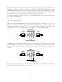
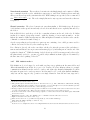
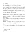
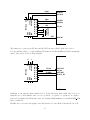
The basic model is to have a reader and a card or tag. The reader is connected to a power source, is
often part of a fixed installation, and generates a strong electromagnetic field whenever it is looking
for cards (which it may be expected to do most of the time).
The card is mobile and has no power source of its own. Instead, it is powered by the field the reader
generates. A the card that is not near a reader receives no power and is therefore not operational.
Power
Power, data
Reader
Reader
Card(s)
Card(s)
Data
Amplitude modulation
Load modulation
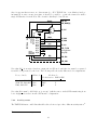
The reader sends data to the card (drawing on the left) by modulating the field it emits. It typically
uses some form of Amplitude Modulation (AM), though other modulation schemes are possible.
The card sends data to the reader (drawing on the right) by changing the characteristics of its
receiver and thus modulating the field created by the reader. This is called load modulation.
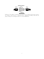
If there are multiple cards in the vicinity of a reader, their transmissions may overlap (“collide”)
and the reader therefore has to select a single one for communication. This process is called “anticollision” and is described in more detail in section 3.4.
2.2
Card structure
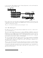
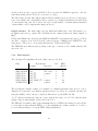
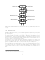
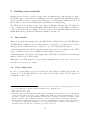
In addition to the radio interface and associated protocol processing, an NFC/RFID card contains
also additional elements, as shows in the following drawing:
3