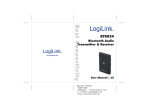
1
According to the European WEEE directive, electrical and electronic equipment must not be disposed with consumers waste. Its components must be recycled or disposed apart from each other. Otherwise contaminative and hazardous substances can pollute our environment. You as a consumer are committed by law to dispose electrical and electronic devices to the producer, the dealer, or public collecting points at the end of the devices lifetime for free. Particulars are regulated in national right. The symbol on the product, in the user's manual, or at the packaging alludes to these terms. With this kind of waste separation, application, and waste disposal of used devices you achieve an important share to environmental protection. Safety Instruction In order to keep the safety of users and your properties, please follow the following safety instructions: 1. This wireless repeater is designed for indoor use only. DO NOT expose this device to direct sun light, rain, or snow. 2. DO NOT put this at or near hot or humid places, like kitchen or bathroom. Also, do not left this Wireless repeater in the car in summer. 3. Do not allow kids to put any small parts of this wireless repeater in their mouth, and it could cause serious injury or could be fatal. If they throw this wireless repeater, it will be damaged. PLEASE KEEP THIS WIRELESS REPEATER OUT THE REACH OF CHILDREN! 4. This Wireless repeater will become hot when being used for long time (This is normal and is not a malfunction). DO NOT put the Wireless repeater on a paper, cloth, or other flammable objects after the Wireless repeater has been used for a long time. 5. There’s no user-serviceable part inside the Wireless repeater. If you found that the Wireless repeater is not working properly, please contact your dealer of purchase and ask for help. DO NOT disassemble the Wireless repeater by yourself, warranty will be void. 6. If the Wireless repeater falls into water, DO NOT USE IT AGAIN BEFORE YOU SEND THE CARD TO THE DEALER OF PURCHASE FOR INSPECTION. - CONTENTS - Declaration ..................................................................................................... 錯誤! 尚未定義書籤。 Chapter I Introduction ................................................................................................................ 3 1.1 Highlights of your new Pan/Tilt IP Camera ....................................................................... 3 1.2 Safety Instructions .............................................................................................................. 4 1.3 Packaging Contents ............................................................................................................ 5 1.4 Familiar with your new Network Pan/Tilt IP Camera ........................................................ 6 1.5 Installation of IP Camera .................................................................................................... 8 Chapter II Using Network Pan/Tilt IP Camera by Web Interface........................................... 14 2.1 IPFinder.................................................................................................................................... 14 2.2 Connect to IP Camera’s Web User Interface and Install ActiveX Plugin ........................... 16 2.3 Viewing Live Video ................................................................................................................. 20 2.4 Client Settings ......................................................................................................................... 23 Chapter III Advanced Configuration ............................................................................................ 25 3-1 System ..................................................................................................................................... 26 3-2 Security .................................................................................................................................... 28 3-3 Network .................................................................................................................................... 30 3-3-1 “General” Setup Page .................................................................................................... 30 3-3-2 “Advanced” Setup Page ................................................................................................. 32 3-3-3 Wireless .......................................................................................................................... 34 3-4 IP Filter..................................................................................................................................... 38 3-5 Video ........................................................................................................................................ 40 3-5-1 Image Setting ................................................................................................................. 40 3-5-2 Video Setting .................................................................................................................. 41 3-5-3 Overlay Setting ............................................................................................................... 43 3-6 Audio........................................................................................................................................ 45 1 3-7 Motion ...................................................................................................................................... 46 3-8 PTZ Control ............................................................................................................................. 48 3-9 Event ........................................................................................................................................ 51 3-9-1 Settings .......................................................................................................................... 52 3-9-2 Media.............................................................................................................................. 54 3-9-3 Event Server ................................................................................................................... 55 3-10 Recording to SD Card .......................................................................................................... 59 3-11 Log ......................................................................................................................................... 60 3-12 Device Info ............................................................................................................................. 61 3-13 Maintenance .......................................................................................................................... 62 3-14 Language ............................................................................................................................... 63 Chapter IV Troubleshooting ......................................................................................................... 64 2 Chapter I Introduction 1.1 Highlights of your new Pan/Tilt IP Camera Congratulates on purchasing this high-resolution 3Mega pixels Pan/Tilt (Wireless) IP Camera! This IP Camera provides 3Mega pixels high-resolution video quality, with the advanced megapixel lens, you can view images remotely in more detail than conventional close-circuit cameras. Other highlights of this Pan/Tilt IP Camera include: Ultra-high resolution 5Mega pixel CMOS image sensor. Full Pan / Tilt Control. Digital input / output interface for peripherals connection such as external alarm, sensor, etc. Audio input / output interface, support full duplex communication in both directions. Built-in SD-card slot for local storage, which can act like a stand-alone DVR. Two Way audio. 3GPP Mobile Surveillance Supported. ONVIF Compliant. Support IEEE802.11b/g/n(WC0009). Equipped with one 3dBi detachable antenna(WC0009). Support WEP / WPA-PSK / WPS2-PSK for wireless security(WC0009). Support motion detection in three independent windows(WC0009). 3 1.2 Safety Instructions Please follow the safety instructions listed below when you’re using this Pan/Tilt IP Camera, or you would harm this camera and / or yourself! Also, the warranty will become void if you disobey these safety instructions. This Network IP Camera is sophisticated electronic device; do not drop it from high places. Do not place this IP Camera at hot / humid places, and avoid direct sunlight. This IP Camera is not a toy; keep it out from the reach of children. Do not insert any accessories of this IP Camera into your body. Make sure lens set is secured when you’re using this IP Camera, lens set may fall down if it’s not properly secured, and cause damage to human and itself. If you want to use this IP Camera at any place that may be spilled by water or dirt, the secure and water-proof camera housing is required. Do not pull any cord that is connected to this IP Camera by force. IP Camera will become hot after long time of use. Refrain from touch IP Camera with hand, or cover this IP Camera with paper or cloth. Never connect powered cable to IP Camera’s DI/DO contacts. If the IP Camera falls into water when powered, do not attempt to retrieve it back by yourself! Find a qualified electric technician for help. 4 1.3 Packaging Contents Please check the contents of your new Network Pan/Tilt IP Camera when you unpack the package. If any item is missing, please contact your dealer of purchase for help. Item No. 1 2 3 4 5 Description WC0008 DC power adapter Wall mounting Kit CD(User Manual) Quick installation guide Quantity 1 1 1 1 1 Item No. 1 2 3 4 5 6 Description WC0009 DC power adapter 3dBi detachable antenna Wall mounting Kit CD(User Manual) Quick installation guide Quantity 1 1 1 1 1 1 5 1.4 Familiar with your new Network Pan/Tilt IP Camera 1 3 4 Item 1 - IR sensor 2 - IR LEDs 3 - Focus LENs 4 - Microphone 5 - LED indicators 2 5 Description Detects light level of the place where this IP camera install. Lights up when it’s too dark If the image looks fuzzy, try to turn this focus ring clockwise or counter-clockwise to adjust focus until the image looks clear Receives voice There are 3 LED lights inside to indicate the operation of this IP camera: Left: Network activity LED On: Transferring data Off: Without connect network Flash: Right: Power LED On: IP camera is switched on Off: IP camera is switched off Please note: These LEDs can be switched off regardless the operation status of IP camera in IP camera’s configuration menu. This will be helpful if you don’t want other people to know the operation status of this IP camera. 6 [Back] DI/DO PIN ASSIGNMENT Item Description GND Signal ground DO Digital Output #1 DI1 Digital Input #1 DI2 Digital Input #2 To insert or release a wire, press the button of the PIN you wish to insert or release. Item 1 - Audio output 2 - DC12V 3 –WPS / RESET 4 - DI/DO connectors 5 – ETHERNET Description Connects to external audio amplifier to output voice. Use 3.5mm audio cable. Connect to DC power adapter output RESET: When the IP camera is not functioning properly, you can use a pen or similar object to press this reset button to reset the IP camera. You can also press and hold this button for more than 5 seconds to clear all settings of IP camera, include administrator password. WPS (For WC0009 only): When you want to connect Wi-Fi AP easy. Please both press and hold this button and AP’s WPS button more than 1 second. The IP camera will connect AP and set value during 5 ~10 seconds. Digital input / output dry contacts. Connects to external peripherals by wire. See next page for pin definitions. WARNING: DO NOT CONNECT POWERED CABLE! Connect to your local area network by Ethernet cable. Getting power from this Ethernet port if this device connects to PoE switch 6 - SD card slot 7 – Connector for detachable antenna(WC0009) Inserts SD card for video recording. Maximum 32GB** of SDHD card supported. Connect the detachable antenna when wireless connection is required. 7 1.5 Installation of IP Camera Please follow the following instructions to setup your new IP camera. Please note: If you wish to place this IP camera on the table, please skip step 1 to 5. 1. Secure the wall mounting metal plate A on the wall, secure it by 4 screws at the screw holes indicated by black arrows. You can secure it upside-down when required. 2. Insert wall mounting metal plate B into the slot at the bottom of this IP camera by the direction indicated by black arrow. 8 3. Secure wall mounting metal plate B by 2 screws. 4. Insert the IP camera (with wall mounting metal plate B installed) into wall mounting metal plate A, which is already secured on the wall. 5. Secure the IP camera on the wall by securing wall mounting metal plate A and B together by screw at the place indicated by black arrow. 9 6. When mounted on the wall, cables can pass through wall mounting metal plate A as indicated by the picture below. 7. Insert Ethernet cable to the Ethernet port of this IP camera for Ethernet connection. 10 8. Insert DI/DO signal cable(s) into DI/DO port of this IP camera. If you don’t have DI/DO accessories, you can skip this step. 11 9. Insert AC power adapter’s cable into DC12V port of this IP camera. 10. The LED lights should light up after few seconds, and the IP camera will test its Pan/Tilt motor within 1 minute (Do not disturb IP camera at this stage). Please refer to following chapters for detailed operating instructions. 11. If it needs to set up wireless connection, please attach the wireless antenna to the IP camera and configure through wired connection. Remove the network cable after finish all relative wireless configuration then user can access the camera through wireless connection. Please refer to the section 3.3.3 for detail configuration. 12 13 Chapter II Using Network Pan/Tilt IP Camera by Web Interface 2.1 IPFinder You can use your new Network Pan/Tilt IP Camera by its web user interface via web browser. Currently only Microsoft’s Internet Explorer is supported. You must know the IP address of IP Camera before you can connect to it. The IP Camera will use DHCP server on your local network to obtain an IP address automatically by default. So, you can check your DHCP server’s IP address lease table to find the IP address of IP Camera. You can also use the utility named ‘IPFinder.exe’ to find the IP address of IP Camera, which is located on CD-ROM: Press ‘Discover’ button to search for all IP Cameras on your local network (make sure all IP Cameras are powered on and connect to local network first). When you find any IP Camera, you can click on it and click ‘Link’ button to connect to it by your web browser. If you need to change a certain IP Camera’s IP address, you can also click on 14 the IP Camera you wish to change IP address, then click ‘Change IP’ button to change select IP Camera’s IP address setting. If you no longer need to use this utility, click ‘Exit’ button to close it. Please note: If you have several network connections, such as “Wireless Function”, please disable the “Wireless Functions” or / and other network connections that is not connected to IP camera, or IP finder may fail to search IP camera! 15 2.2 Connect to IP Camera’s Web User Interface and Install ActiveX Plugin When you know the IP address of IP Camera, you can connect to it by Internet Explorer web browser by entering its IP address in address bar. The use login screen will appear when you get connected: The IP Camera’s administrator username and password are both ‘admin’ (lower case) by default. Click ‘OK’ button or press ‘ENTER’ key on your keyboard when you finish entering username and password. When you connect to IP Camera for the first time, you’ll see the following message: This message prompts you that you need to install ActiveX plugin before you can see the video from IP Camera. For IE 8 and earlier version: 16 Right click the indication bar and click: ‘‘Install This Add-on for All Users on This Computer…’ to install ActiveX plugin. For IE 9: Click ‘Install’ button located at the bottom of IE to install ActiveX plugin. 17 If you’re prompted that: ‘Windows Firewall has blocked some features of this program’ Click ‘Allow access’, or IP Camera will not be able to function properly. When you’re installing Internet Explorer plugin, you may also be prompted that if you want to allow changes to be made to your computer: Click ‘Yes’ to allow changes. 18 After ActiveX plugin is installed, you should be able to see the video stream from camera. NOTE: If this is the first time you use this IP Camera, you can jump to chapter 2.4 for instructions on Setup Wizard, which will guide you to complete the software setup of your new IP Camera. 19 2.3 Viewing Live Video After ActiveX control is installed, you can view IP camera’s video by web browser. Just connect to IP camera by web browser and login, then you can see live video from IP camera: There are various controls on web page, here are descriptions of every control item: Item Description ‘Home’ button This button is visible in all setup pages of IP camera, and you can go back to live video view by clicking this button when you’re in other page. Stream Select video stream type: H.264 or MJPEG. H.264 required less network bandwidth and this will help when network connection is slow. Digital Output Switch digital output interface on or off. (ON / OFF) Client Settings Open ‘Client Setting’ menu. Configuration Open ‘Configuration’ menu. Language Open language menu, you can switch web interface to other language. Available languages: English, Simplified Chinese, Traditional Chinese, German Original size / Switches live image view between original size (full Fit screen size: 3M pixels) and fit screen (smaller size). If you want to see video in detail, switch to original size. 20 / ‘Connect’ button If your computer monitor’s resolution is not enough and you want to see full image view, switch to fit screen and image size will adjust automatically. Start live video view. ‘Disconnect’ button Stop live video view. ‘Snapshot’ button Take a snapshot or camera video and save image file on your computer. When you click this button, a new window will appear: Click ‘Save’ button when you see the image you wish to save, and you’ll be prompted to indicate the folder on your computer to save image file. If you changed your mind and don’t want to save image file, click ‘Cancel’. ‘Start Record’ button Video Click this button to record video and save video file on your computer. You’ll be prompted to indicate the folder on your computer to save video file. ‘Enable Digital Zoom’ button This function will enlarge video view digitally from 1X to 10X, so you can see objects in video in detail. Please note: that digital zoom uses computer algorithm to enlarge the video and some details may lost. If you need to focus on detail of specific objects in video view, 21 please use optical zoom ring on lens set of IP camera. Enable / Disable When mute is enabled ( ), you will not hear the voice mute button from IP camera; If you want to hear voice from IP camera, click this button to disable mute ( ). / ) beside You can drag the slide bar ( enable/disable mute button to adjust audio playback volume. Start / Stop talk Start or stop playing your voice through IP camera’s Button audio output. When talk is stopped, people at IP camera will not hear you. / Please note: you need a microphone connected to your computer, and computer’s mixer setting must enable microphone recording, or nothing will be outputted by IP camera. 22 2.4 Client Settings In ‘Client Settings’ menu, you configure basic IP camera settings like data transfer protocol and data storage folder. To access ‘Client Settings’ menu, click ‘Client Settings’ button on the left. The following screen will appear: 23 Here are the descriptions of every setup item: Item Description RTSP Select this option to use RTSP (Real-Time Streaming Protocol) to transfer video data. HTTP Select this option to use HTTP (Hyper-Text Transfer Protocol) to transfer video data. If you don’t know which one you should use, select ‘RTSP’. Folder Select a folder on your computer to save recorded video. Click ‘Browse’ button and you’ll be prompted to select a folder. Prefix When saving video files, the characters you typed in ‘Prefix’ field will be used as leading characters of video file’s name. For example, the default setting of ‘Prefix’ is ‘CLIP’, and video file’s named will be ‘CLIP.avi’. Add date and time Check this box to add data and time to the ending part suffix to file name of video file’s filename, so you can see the date and time the video file is created directly from its filename. When you finish with above settings, click ‘Apply’ button to save changes. 24 Chapter III Advanced Configuration If you wish to configure IP camera’s settings, you can access IP camera’s ‘Configuration’ menu, which provides various kinds of system setting. To access configuration menu, click ‘Configuration’ button on the left. The ‘Configuration’ submenu will appear, please pick a setup item you wish to configure. 25 3-1 System In this menu, you can configure basic IP camera settings like hostname and time. Here are the descriptions of every setup item: Item Description Host Name Input the IP camera’s hostname here, it can be any meaningful words or characters that will help you to identify this IP camera. You can use IP camera’s installation location as host name, and this will help you to identify IP camera when you have many IP cameras installed. Indicator LED The LED lights located at the back of IP camera is switched on by default. But, if you don’t want other people to know the status of this IP camera (so they will know this IP camera is operating etc.), you can select ‘Off’ and LED lights will be switched off. Timezone Select the time zone of residence from dropdown menu to keep correct date and time. 26 Daylight Saving Keep the current date and time Synchronize with computer time Synchronize with NTP Server If the area you live uses daylight saving, check this box; otherwise do not check this box to keep time correct. Select this option and date / time setting will not be changed when you click ‘Apply’ in the page. You can check ‘Camera Date and Time’ item in this page to know IP camera’s current date and time setting. Select this item and IP camera will use your computer’s time as its time. Select this item and IP camera will keep its date and time setting synchronized with specified time server (NTP server). Please input NTP server’s IP address or host name in ‘NTP Server Address’ field, and select time update interval from ‘Update Interval’ dropdown menu. Please note that if this IP camera can’t access Internet, you must have a time server on local area network, or set the time manually. Set Manually Set IP camera’s date and time manually. Please set current date and time by ‘Date’ and ‘Time’ dropdown menu. When you finish with above settings, click ‘Apply’ button to save changes. 27 3-2 Security In this menu, you can configure IP camera’s login account. There are three kinds of account: - Administrator (Can view IP camera’s video and make changes of camera setting) - User (Can view IP camera’s video and see LOG, and change Client Setting and language) - Guest (Can view IP camera’s video , and change language ) There can be multiple users, but only one administrator is allowed, and you can’t change administrator’s user name (it will always be ‘administrator’). 28 Here are the descriptions of every setup item: Item Description Password / Retype Input administrator’s new password in both ‘Password’ Password and ‘Retype Password’ field, and click ‘Modify’ button to change administrator’s password. (Administrator) Please note: Don’t forget administrator’s password! Or you’ll need to reset IP camera’s all settings to get administrator’s password recovered. Account List Here lists all users existed in IP camera. If you want to remove one user, click it in the list, and then click ‘Remove’ button. If no user is existed, ‘New Account’ message will be shown here. User Name Input new user’s username here. User name must be greater than 1 character and less than 32 characters. Password / Retype Input this user’s password in both ‘Password’ and Password ‘Retype Password’ field. Authority To define this user’s access privilege, select ‘User’ or ‘Guest’ in dropdown menu. When you finish inputting new user’s information, click ‘New’ button to create a new user. 29 3-3 Network You can configure the network camera’s general and advanced network settings here. 3-3-1 “General” Setup Page Set up IP address for this IP camera. This IP camera supports both IPv4 and IPv6 IP address. 30 Here are the descriptions of every setup item: Item LAN Description Select this option to assign an IP address to LAN port (or obtain an address from DHCP server automatically). Available options are: DHCP IPv4: Obtain an IPv4 IP address from DHCP server on LAN automatically. DHCP IPv4 / IPv6: Obtain both IPv4 and IPv6 address from DHCP server on LAN automatically. Static IPv4 / IPv6: Assign an IPv4 / IPv6 address to IP camera manually. If you don’t have a DHCP server on your local area network, you must use this option to specify an IP address. IP Address(IPv4): Input IPv4 IP address* IP Address(IPv6): Input IPv6 IP address* Prefix Length: Input IPv6 IP address’ prefix length (0-128) Subnet Mask: Input subnet mask Gateway: Input gateway address Primary DNS: Input DNS server’s IP address Secondary DNS: Input backup DNS server’s IP address, you can leave this field blank. * You can leave this field blank, if you only wish to use IPv4 or IPv6 IP address. Enable UPnP Discovery: Check this b ox to enable other devices on network to discover the presence of this IP camera by UPnP. It’s recommended to enable this function. PPPoE Enable UPnP Port Mapping: When UPnP is enabled, check this box to enable UPnP’s port mapping. Select this option to use PPPoE to connect to network. You 31 HTTP Port have to input PPPoE username and password assigned by network operator to get connected. Input IP camera’s web connection port number here. When this port number is changed, you need to change web browser’s port number you used to connect to IP camera. For example, IP camera’s IP address is 192.168.2.3, and if you changed HTTP port number to 82, please input ‘http://192.168.2.3:82’ in web browser’s address bar to access IP camera’s web configuration interface. RTSP Port Input RTSP port number. When this port number changes, you must change corresponding settings in external network devices (NVR or CMS software) so they can receive this IP camera’s video. RTP Data Port Input RTP data port number here. When you finish with above settings, click ‘Apply’ button to save changes. 3-3-2 “Advanced” Setup Page You can setup advanced network settings in this page. This page is intended for advanced settings only, and this IP camera will work fine even you don’t make any changes to this page. 32 Here are the descriptions of every setup item: Item Multicast Description Enable video multicast: Multicast Group Address: Input multicast group address here, must be an address between 232.0.0.0 to 232.255.255.255. Multicast video port: Input port number for video multicast here. Multicast RCTP video port: Input port number for RCTP video here. Multicast audio port: Input port number for audio here. Multicast RCTP audio port: Input port number for RCTP audio here. Bonjour QoS DDNS Multicast TTL: Input TTL value for multicast here. If you’re using MacOS and you have Bonjour installed, you can use it to discover this IP camera. Enable QoS to improve the data transfer priority of this IP camera (Your local area network must support QoS). You can select Video / Audio’s QoS DSCP value (0 to 63), or both video and audio. Enable DDNS support if your ISP assigns dynamic IP address to you. You must register a dynamic IP service first. Currently this IP camera supports Dyndns and TZO dynamic IP service. Provider: Select dynamic IP service provider. Host Name: Input the host name you obtained from dynamic IP service provider. User name: Input user name used to login dynamic IP service provider. 33 HTTPS Password: Input the password used to login dynamic IP service provider. Check ‘Enable HTTPS’ box to enable HTTPS channel to encrypt transferred data. You can also define HTTPS port number in ‘HTTPS Port’ field if you don’t want to use default value ‘443’. When you finish, click ‘Apply’ to save changes. 3-3-3 Wireless(WC0009) 34 The descriptions of every setting in this menu will be given below: Item Wireless Connection Network Type Available Networks Description Select „Enable‟ to activate wireless network function of this IP camera, select „Disable‟ to disable it. Select the network type of wireless connection. Available options are „Infrastructure‟ (Connect the IP camera to a wireless access point), and „Adhoc‟ (This IP camera will become a stand-alone wireless network point, other wireless computers / devices can discover this IP camera and connect to it without wireless access point). You can set to „Adhoc‟ when you don‟t have any wireless access point, but your computer has wireless network card. Set to „Infrastructure‟ when you have wireless access point, and you have computers with wired network connection. Here shows all wireless access points found by this IP camera. Please note not all access points will be displayed at the same time, if the access point you expected to connect does not appear, you may have to click „Refresh‟ button for several times until it appears. The descriptions of all fields is listed below: Connect: You can select the wireless access point you wish to connect here. SSID: the SSID of all found wireless access points will be shown here. Some wireless access point may hide their SSID; in this case, you have to identify them by their MAC address. MAC Address: If you there are many wireless access points in proximity or some wireless access point hides it‟s SSID, you can use MAC address to distinguish them. Signal: Shows the radio signal strength in percent. Channel: Shows the radio channel of this wireless access point. Encryption: Shows the encryption type used by this wireless access point. You must use the same encryption type if you wish to connect to a certain wireless access point. If the wireless access point does not use encryption, „Disabled‟ will be displayed here. Network Type: Shows the network type of a certain wireless access point (Infrastructure or Adhoc). 35 SSID Channel Authentication Input the SSID of the wireless access point you wish to connect. It should be less than 32 alphanumerical characters. When you select a wireless access point above, it‟s SSID will be filled in this field automatically. However, if the SSID is not displayed (the wireless access point you selected choose to hide it‟s SSID), you have to know it‟s SSID and input it here, or you will not be able to connect it. Select the radio channel you wish to use here. When network type is „Infrastructure‟, the radio channel is auto-selected according to the channel that wireless access point uses. You can only select the channel number when network type is „Adhoc‟. It includes None, Open System, Shared Key 64bits and 128bits, WPA-PSK, WPAS-PSK. Select one of them then the relative items below will transfer gray scale to black scale. Configure the setting consistent with the setting on the wireless router/AP that this IP camera will join the wireless network. Apply the settings then check the wireless networking. 36 Pin Code Configure via Push Button Configure via PinCode Here displays the WPS pin code used to connect to WPS-enabled wireless access points. You have to input this number into the WPS enabled access point to establish WPS connection. Click this button and this camera will enter PBC-style WPS connection state for 120 seconds. Please push „Start PBC‟ button on the wireless access point you wish to connect within 120 seconds to establish WPS connection (The remaining time will be displayed on the button). If connection can not be established after 120 seconds, you‟ll be prompted by a message box, and you can press „Start PBC‟ button to try again. If you have wireless access point’s WPS PIN code, you can input it here and press „Start PIN‟ button to start to establish PIN-style WPS connection. 37 3-4 IP Filter When this IP camera is directly connected to Internet and not protected by firewall, this function acts like an mini built-in firewall to protect the safety of this IP camera and avoid attacks from hackers. Here are the descriptions of every setup item: Item Description Enable Filter Check this box to enable IP address filter, uncheck this Box to disable this function. Accepted IP list Here lists all IP address that can build connections to this IP camera. If you want to remove a set of IP address from the list, click on the IP address and click ‘Remove’ button. IP Address Input the starting and ending IP address of IP address you (Accepted IP wish to accept connections here. IP camera will only accept connections established from these IP address. list) If you want to specify one IP address only, input the 38 same IP address in both field. Click ‘New’ button to add IP address into accepted IP list. Deny IP list Here lists all IP address that cannot build connections to this IP camera. If you want to remove a set of IP address from the list, click on the IP address and click ‘Remove’ button. IP Address Input the starting and ending IP address of IP address you (Accepted IP wish to deny connections here. IP camera will deny connections established from these IP address. list) If you want to specify one IP address only, input the same IP address in both field. Click ‘New’ button to add IP address into deny IP list. When you finish with above settings, click ‘Apply’ button to save changes. 39 3-5 Video You can adjust the image of the IP camera in this menu. There are 3 sub-menus in this menu: Image Setting, Video Setting, and Overlay, which can be accessed by tabs on the top: Image Setting, Video Setting and Overlay. 3-5-1 Image Setting You can adjust the image parameters in this page. 40 Here are the descriptions of every setup item: Item Brightness / Contrast / Saturation / Sharpness Default Mirror Description Control the image parameters. Click ‘ - ' to decrease value, or click ‘ + ‘ to increase value. You can also input the value in the field directly. Set all above values to default value ‘128’. Check ‘Vertical’ or ‘Horizontal’ box to flip the image vertically or horizontally, this will help to correct the orientation of image when IP camera is hanged bottom-up by camera holder. You can click both ‘Vertical’ and ‘Horizontal’ box at the same time. Power Line Select the frequency of power line of the place you’re using this Frequency IP camera. This will help to reduce the flicker of certain lights in the image. When you finish with above settings, click ‘Apply’ button to save changes. 3-5-2 Video Setting You can adjust the video transfer parameters in this page. 41 Here are the descriptions of every setup item: Item H.264 /MPEG4 Video Resolution Description Select the compression of main stream: H.264 / MPEG4. Select video resolution. - H.264: 2048x1536 (QXGA) / 1920x1080 (1080p) 1280x960 (960p) / 1280x720 (720p) 720x480 (D1) / 640x480 (VGA) 320x240 (QVGA) - MPEG4: 1920x1080 (1080p) / 1280x960 (960p) 1280x720 (720p) / 720x480 (D1) 640x480 (VGA) / 320x240 (QVGA) MJPEG: 1280x720 (720p) / 720x480 (D1) 640x480 (VGA) / 320x240 (QVGA) Please note that some video resolution is not available when video encoder is ‘MPEG4’. Please note that MJPEG is not available when the resolution of “H.264” & “MPEG4” is higher than 1280 x 720 (720p). When network speed is insufficient, select a lower video resolution will help. Frame Select video frame rate. Please note that some frame rate is Rate not available when video encoder is ‘H.264’. When network speed is insufficient, select a lower frame rate will help. Rate Select video bit rate. You can control bit rate by both ‘Video Control quality’ and ‘Bitrate’: - Video quality: There are 5 levels of video quality, select ‘very high’ to improve video quality but consumes more network bandwidth, and select ‘very low’ will decrease video quality and consumes less network bandwidth. - Bitrate: Input video’s bit rate directly. It must an integer between 512 and 4000. Higher bit rate provides better video quality, but consumes more network bandwidth. When you finish with above settings, click ‘Apply’ button to save changes. Note: Mobile View is enabled to remote monitor by I-Phone or Android Google phone APP. 42 3-5-3 Overlay Setting You can adjust the video overlay parameters in this page. Here are the descriptions of every setup item: Item Description Enable Time Check this box to enable overlaying time stamp on video. Stamp Remove the Check this box to remove time stamp’s background color. background You may find this will help the readability of time stamp color of the text text in some cases. (for Time Stamp) Enable Text Check this box to display certain text on video, this will Display help when you need to identify certain IP camera when you have a lot of IP cameras. Please input the text in ‘Text’ field. You can input up to 15 characters. 43 Remove the background color of the text (Text) Check this box to remove custom text’s background color. You may find this will help the readability of text in some cases. Enable Image Overlay Check this box to overlay a specific image on video, so you can show certain text / picture on the video and help people to identify this IP camera. Click ‘Browse’ button to pick a picture on your computer, then click ‘Update’ button to use the picture. Please note that there are certain restrictions: - Select .bmp / .jpg / .jpeg image files only. - Image’s resolution should be less than 160 x 128, and can be divided by 4. - Do not upload image files that size is greater than 64KB. When you finish with above settings, click ‘Apply’ button to save changes. 44 3-6 Audio You can adjust audio input / output parameters here. Here are the descriptions of every setup item: Item Enable Microphone Audio Type (Microphone) Microphone Gain Enable Speaker (Speaker) Audio Type (Speaker) Description Check this box to enable microphone. If you don’t want to hear voice from IP camera, you can uncheck this box to disable it. The format is fixed as G.711 If the voice received by microphone is too loud or silent, you can use this function to improve voice volume, so you can hear voice from IP camera more clearly. - Select 0 dB and IP camera will do nothing on the voice; - Select +6 dB to +18 dB to amplify the voice. Check this box to enable speaker. If you don’t want people at IP camera to hear you, you can uncheck this box to disable it. The format is fixed as G.711 When you finish with above settings, click ‘Apply’ button to save changes. 45 3-7 Motion This IP camera is capable to detect object’s motion, so IP camera will only record when there’s motion and save disk storage space. Motion detection is performed by examine the movement of objects in rectangular motion detection area. You can define up to 3 motion detection areas. 46 Here are the descriptions of every setup item: Item Enable Motion Detection Enable (Window 1 to Window 3) Title (Window 1 to Window 3) Percentage Sensitivity Description Check this box to enable motion detection. Check this box to enable this motion detection window. You can select window 1 to 3 to enable up to 3 motion detection windows. When a motion detection window is enabled, a rectangular will appear on camera’s view, with its title on the top. - To move / resize a motion detection window: - Move: Use the mouse to drag the title text. - Resize: Use the mouse the drag the four corners (upper-left/right, lower-left/right) to resize it. If you only want to adjust width or height, drag the four sidebars (top, bottom, left, and right). Input characters in title field to change motion detection area’s title text so you can identify it. Please note that you have to click ‘Apply’ button and the text will change. Select the percentage of pixel change that will trigger motion detection alert. Select a lower percentage and you can detect tiny changes in motion detection area. Select the sensitivity level that will trigger motion detection alert. Select a higher sensitivity and you can detect tiny changes in motion detection area. When you finish with above settings, click ‘Apply’ button to save changes. 47 3-8 PTZ Control In this page, you can setup PTZ Control settings like auto pan-tilt control and patrol. 48 Here are the descriptions of every setup item: Item Pan-tilt control Description Control pan-tilt of camera by click up, down, left, right and upper-left/right, lower-left/right. Pan Speed Adjust the pan speed. It should be an integer between 1 (slower) to 10 (faster). Adjust the tilt speed. It should be an integer between 1 (slower) to 10 (faster). Click this button to set current position as home position. To calibration its direction and focus to its “Factory Default Position”, to ensure its preset position will be located at the correct position without deviation after a period of usage. This IP camera supports up to 8 preset points. You can move camera to preset point, and camera will stop there for a specific amount of time. You can specify up to 8 preset points. Tilt speed Set home Calibration Preset list To set a preset point: Move camera to the preset point you wish to set by pan-tilt control. Select a preset point from the list (1 to 8) Input a text description for this preset point (this is optional, up to 16 characters). Input dwelling time (0 to 30**, seconds) Click ‘Set’ to save current preset point. Patrol Setting You can click ‘GO Preset’ button to move camera to preset point, or click ‘Remove’ to clear this preset point setting. When you have 2 or more preset points, you can 49 make camera to move between these points, this function is called as ‘Patrol’. To configure patrol, please setup preset points first, then select preset points from ‘Preset list’ and click button to add it to ‘Patrol’ list; to remove a preset point from patrol list, select it in patrol list and click button. You can also adjust the order or preset points in patrol list: select a preset point and click or button. When you finish, click ‘Apply’ button. 50 3-9 Event When there’s an event, you can use this setup page to define what IP camera should do, like send an Email or trigger digital output to activate external alarm. 1. Setting: Define a new event and manage events. 2. Media: Define what kind of media file should be saved on designate media. 3. Event Server: Define the details of remote server. Please refer to following chapters for detailed instructions. 51 3-9-1 Settings This page lists all existing events. You can click ‘Modify’ button to edit an existing event, or ‘Remove’ to delete an existing event. To create a new even, just click “New” button to add an Event setting. 52 To add a new event, click ‘New’ button and the descriptions of every setup item is listed below: Item Enable Setting Title Motion Detection Digital Input 1~2 Enable Schedule Time Enable FTP Enable EMAIL Enable Samba (Net Storage) Enable SD CARD Trigger digital output for xx second(s). Description Check this box to enable this event. If you just want to disable this event temporarily, you can uncheck this box to keep this event and disabling while not deleting it. Input any description text for this event so you can identify it quickly. You can use alphabets, numbers, and symbols include: !$-.@^_~ (no spaces allowed). Check this box and this event will be activated when one of motion detection window detects motion. Check this box and this event will be activated when digital input 1 or 2’s input signal is high or low (select from dropdown list). Check this box and this event will be activated when designated weekday and time is reached. You also have to check weekday box, and select time from dropdown list. If you select ‘Always’ as time, this event will be activated during all the day. Check this box and IP camera will save file on FTP server (refer to ‘FTP Server’ setting in ‘Event Server’ tab) when this event is activated. Check this box and IP camera will send an Email to designated recipient address (refer to ‘SMTP Server’ setting in ‘Event Server’ tab) when this event is activated. Check this box and IP camera will save file on samba server (refer to ‘Samba Server’ setting in ‘Event Server’ tab) when this event is activated. Check this box and IP camera will save file on SD card when this event is activated. A working SD card must be inserted into IP camera in advance. Check this box and IP camera will trigger digital out to ‘high’ state for xx seconds when this event is activated, where ‘xx’ seconds must be defined by the dropdown list. 53 3-9-2 Media You can define what kind of media file should be saved on designated media. Here are the descriptions of every setup item: Item Description One Save a picture file when event is triggered. Snapshot Please note that this function will be enabled while “MJPEG codec” is appeared on the “Video Setting”. (Please refer to section “3-5-2 Video Setting”. H.264 Video Save a H.264 video clip. You can also select the recording length before and / or after the time when event is triggered in ‘Pre Event’ and ‘Post’ Event’. For example, if you set ‘Pre Event’ to ‘10’ and ‘Post Event’ to 5’, and an event is triggered at 14:10:30, then the video file will be 15 seconds long, starting from 14:10:20 to 14:10:35. Tips: You may want to know what happened before event is triggered in many cases, especially when object is outside of motion detection window. Note: If the “Pre Event” set to “0” second, the “Post Event” cannot set to “0” second. When you finish with above settings, click ‘Apply’ button to save changes. 54 3-9-3 Event Server You can define the details of remote media server: FTP (File), SMTP (Email), and Samba (File). A Samba server can be any computer running windows operating system with network neighbor function enabled. Many stand-alone network file server also support samba server function. 55 Here are the descriptions of every setup item: Item Enable FTP Server Description Check this box to enable FTP server upload. FTP Server: Input FTP server’s IP address or hostname. Port: Input FTP server’s port number. In most cases it should be default value ‘21’. User Name: Input FTP server’s username. Password: Input FTP server’s password. File Path Name: Input the path where you want to save file on FTP server, like ‘upload/record’. If you want to save file on this FTP user’s home directory, you can leave this field blank. Enable Passive Mode: Check this box to force IP camera to communicate with FTP server in passive mode (Some FTP Server may only work when you check this box, while others don’t). Test FTP: Click this button to test FTP server settings above immediately. 56 SMTP Server Check this box to enable Email send. SMTP Server: Input SMTP server’s IP address or hostname. Port: Input SMTP server’s port number. In most cases it should be default value ‘25’. Sender Email Address: Input the sender’s email address that will appear in the Email send by IP camera. This will help you to identify the Email sent by this IP camera, and may help when you have anti-spam software installed (you can set this Email address to ‘White List’ in your anti-spam software) Receiver #1 Email Address: Input primary recipient’s Email address. This field is required. Receiver #2 Email Address: Input backup recipient’s Email address. This field is optional. Subject: Input Email title that will appear in the Email send by IP camera. This will help you to identify the Email sent by this IP camera. Authentication: Check this box when authentication is required by the Email server you’re using. You also need to input Email server’s username and password in corresponding field. Requires SSL Encryption: If your Email server required SSL encryption, check this box. Please note that some Email server 57 Samba Server uses different port number than standard port 25 when SSL encryption is used. STARTTLS: If your Email server required STARTTLS encryption, check this box. Please note that some Email server uses different port number than standard port 25 when STARTTLS encryption is used. Test SMTP: Click this button to test SMTP server settings above immediately. Check this box to enable Samba server file upload. Samba Server Address: Input Samba server’s IP address or hostname. Path: Input the path where you want to save file on Samba server, like ‘upload/record’. If you want to save file on this user’s home directory, you can leave this field blank. User Name: Input Samba server’s username. Password: Input Samba server’s password. Test SMB: Click this button to test Samba server settings above immediately. Tips: Some samba server does not have username and password check, you can just input samba server address and path to access the file storage space. When you finish with above settings, click ‘Apply’ button to save changes. 58 3-10 Recording to SD Card When a SD card is inserted into IP camera, you can save video files on it. Note: 1. Be sure that the SD Card format should be FAT32. The NTFS format cannot be supported by this camera. 2. Unlike motion detection, this function will record video at specified time period on selected weekday(s). Here are the descriptions of every setup item: Item Enable External storage Recording Maximum Size of Each File Description Check this box to record video on SD card. Input the maximum size of every video file from 1MB to 50MB. IP camera will start a new video file when a recording video file reaches the size limit stated here. Recording Define the recording schedule. You can check Sun to Schedule Sat boxes to represent a weekday, and specify time period in ‘From’ and ‘To’ field. Select ‘Always’ to record 24 hours in selected weekday(s). When you finish with above settings, click ‘Apply’ button to save changes. 59 3-11 Log You can check the usage log of IP camera here. In this page, you can click: 1. First page / Final page: Jump to first / final page of log. 2. Previous / Next: Jump to previous or next page of log. 3. Remove: Clear log. You’ll be prompted for confirmation. 60 3-12 Device Info You can check the information and network settings of this IP camera. These information are very useful when you need to repair or fix the problem of this IP camera. An example of device info page look like this: 61 3-13 Maintenance You can do some maintenance job about this IP camera here. Here are the descriptions of every setup item: Item Reboot Description Click this button to reboot the IP camera. This function is useful when you find IP camera is not working properly. Reset Clear all settings of IP camera and reset to factory default setting. Backup Backup IP camera’s setting and save it on your computer. Backup to SD Backup IP camera’s setting and save it on SD card. A SD card device card must be inserted into SD card slot when you click this button, or you’ll receive an error message. Restore Restore a previously-saved configuration file saved on your computer. Click ‘Browse’ button to select a file on your computer first, then click ‘Restore’ button. Restore from Restore IP camera’s configuration which is SD card previously-saved on SD card. device Upgrade Upgrade IP camera’s firmware. Click ‘Browse’ button to select a firmware image file on your computer first, then click ‘Upgrade’ button. 62 3-14 Language You can change the display language of web interface. Click ‘Language’ button and select one language. More languages may available in latest firmware file. 63 Chapter IV Troubleshooting Please don’t panic when you found this IP Camera is not working properly. Before you send this IP Camera back to us, you can do some simple checks to save your time: Problem description Can’t connect to IP Camera Possible solution(s) 1) Please check the IP address of IP Camera again. 2) Please make sure the network cable is correctly connected to your local area network. 3) Please make sure power cable is correctly connected to IP Camera. No IP Camera found No image Image is fuzzy 4) Please make sure IP Camera is switched on (the LED lights on IP Camera will light up). 1) ‘Auto search’ function only works on IP Camera s located on local area network. 1) If the place where IP Camera is installed is too dark, try to add some lights when possible. 2) Check if there’s anything covering the lens. 1) Check the lens and make sure it’s clean. If it’s dirty, use cloth with clean water to clean it, do not use alcohol or other chemical-based solution. 2) Adjust focus ring until image looks clear. CE Declaration: This device corresponds to EU directive 1999/5/EC and 2006/95/EC: With the CE sign Logilink®, a registered trademark of the 2direct GmbH ensures, that the product is conformed to the basic standards and directives. These standards can be requested online on www.logilink.com. All trademarks and registered brands are the property of their respective owners. 64