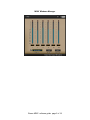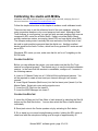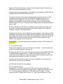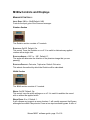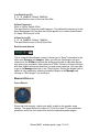
1
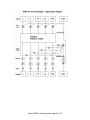
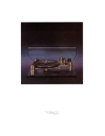
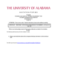
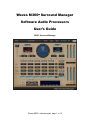
Waves M360° Surround Manager
Software Audio Processors
User’s Guide
M360˚ Surround Manager
Waves M360˚ software guide page 1 of 18
M360˚ Mixdown Manager
Waves M360˚ software guide page 2 of 18
Introduction and Overview
Introducing Waves M360°, a Surround Managing tool for 5 or 5.1 channels. This
tool offers Studio Monitoring Calibration and Bass Management solutions for
working on surround sound productions.
The Waves M360° manager allows you to monitor with a Satellite and Subwoofer
system (“Sub/Sat”) with flexible control of the Subwoofer feed as well as
individual channel gain and delay settings.
The Waves 360° Surround Toolkit follows the reproduction standards
recommended by the International Telecommunications Union in the ITU-R
BS.775 (1993). It also provides means to handle some common compromises
and variations of this standard. The M360°’s versatility allows it to complement
your work style. You will find it the tool of choice for working on soundtracks or
music for the best reproduction in Home Theater systems.
We believe that, with practice, surround will become as easy to work with as
stereo. There is, however, a potential problem with how the consumer’s actual
playback system is configured and calibrated. Even if the playback system is fully
calibrated and conformed to ITU recommendations, this is not the ideal array for
playing a spatial 360° spherical sound field, but it is the common one in
consumer electronics.
Overview of the M360°
The M360° has two plug-in components – M360° Manager and M360° Mixdown.
The M360° Manager is designed to insert on the master surround output. It is
dedicated to carry out some important chores:
• Allow calibration of the studio monitoring system.
• Setup monitoring with a Sub/Satellite (“Sub/Sat”) playback system.
• Preview standard 5.1 target playback processing.
The M360° Mixdown can be inserted directly after the Manager to preview or
apply Mixdown options.
IMPORTANT: In most cases the M360° Manager will be used for Monitoring
calibration and should be bypassed at Mixdown.
If your studio monitoring system elements are well-matched and the speaker
setup is conformed to the ITU recommendation, the use of the manager in
production should be quite minimal.
Waves M360˚ software guide page 3 of 18
Tweaking gains and delays is a common way to calibrate the sound stage,
achieving a steadier all round image and better directionality and localization of
phantom images. Bass management is necessary for proper Sub/Sat monitoring
in surround production facilities as well as Home Theater reproduction systems.
Here, the manager can replace hardware bass management alternatives from
within your DAW. You can safely use the LFE or .1(point one) channel output as
your Subwoofer feed. It will output both the redirected SUB signal and the LFE
channel as if they were separate elements each with its own gain, mute, solo and
invert.
The M360° Manager can be used in many ways, but the basic recommendation
is to insert it on the Master surround output and use it for calibration of levels and
speaker positions.
We strongly recommend that you calibrate your studio. A step-by-step calibration
procedure using the M360° manager was written by Bobby Owsinski and is
provided with this product so that you can calibrate and mix like the pros. Once
you have calibrated, we recommend boldly mixing a 5 or 5.1 channel image.
After the mix is ready, bypass the manager and print it. This will create a
straightforward ITU standard compliant image.
IMPORTANT: Be sure to bypass M360° Manager when printing your mix.
This manual will describe many optional applications and choices. Don’t be
alarmed by the multitude of features, they are here to serve you if you should
need them and not to add confusion to the production process. Read the chapter
on Production Disciplines for more suggestions.
The Surround Manager will only instantiate on 5 or 5.1 channel inserts.
LFE vs. SUB
The LFE channel and the Subwoofer signal are two different signals. They are
often confused with each other.
The LFE is a channel that’s used for Low Frequency Effects such as Explosions
or Dinosaur footfalls in film. You can use the LFE filter to apply a very steep LowPass filter at 120Hz or rely on an external encoder to filter it for you.
The SUB signal consists of redirected low frequencies from the directional
“Satellites” or L, C, R, Ls and Rs channels. The full-bandwidth signal of each
channel is split by a crossover to its high frequencies feeding the Satellite
speakers and Low frequencies redirected to the SUB.
Waves M360˚ software guide page 4 of 18
The Subwoofer feed combines the LFE channel audio (boosted by 10dB) with
the SUB signal. While the LFE channel is created in production and printed to
the master, the Subwoofer feed is created by the Bass Management portion of
the playback system and isn’t printed to the master.
Using M-360°
Basic Operation
To enjoy the full capacity of the M-360°, use the Manager as an insert on the
Master Surround output channel. It is recommended to go through the studio
calibration routine provided with this product before you begin to pan sources
using the S360° components. If your studio is not set up according to ITU
recommendations, adjust your speaker angles in the Manager so that the panpots will perform optimally in this setup. Even if you are sure that your studio is
well-calibrated, it is still recommended to insert the manager for further fine
tuning. We recommend that you create a custom work setup for your studio and
use it as your convenient default.
Manager Usage:
When you insert an M360° Manager on your master output you can use it for the
following applications:
• Adjust the speaker angles to the ones in your studio to work with the S360°
Panner – This will provide optimal translation of the mix you make to the
standard ITU recommendation.
• Use per-channel gain and delay to align the level and phase of all speakers –
This will assure that the directionality of the image is solid and not pulling in a
certain direction because of speaker level or phase differences.
• Use more target adjustment options to account for –3dB surrounds, +10dB
LFE playback or other options that relate to encoders and settings available in
consumer playback systems.
• Use Bass management to set up proper monitoring using a Sub/Sat
monitoring system.
Calibrating the studio monitoring system is the first step which should be
performed before you begin to mix. Essentially the calibration settings will allow
you to trim the gap between your listening environment and the standard ITU
spec. The Manager behaves like a correcting lens. Remember to bypass
Manager for Mixdown
Waves M360˚ software guide page 5 of 18
ADVANCED CALIBRATION OPTIONS
On top of just basic gain and delay calibration, the M360° manager allows you to
further calibrate speaker angles and make target adjustments.
Speaker Angles Calibration
Speaker angles calibration is required for setting internal rotation and width
algorithms to perform precisely per the default ±30° for L and R speakers and
±110° for the Ls and Rs speakers. You should measure the angle of your
speakers and update the value in the related control. The Speaker angles can be
sent to every instance of S360° Panner or Imager in order to further boost the
precision of the pan pots.
The plug-in top toolbar offers a “Send Angles” button. Whenever this button is
clicked the speaker angles set in the manager will be used in any S360° Panner
or Imager. Before you print a mix, it is important to send angles again to zero the
angle values in all Instances of S360° Panner or Imager. The Interface will
always show the Speaker icons at their ITU recommended angle but the beams
within the Graphs will represent the calibrated angles. This view allows you to
see the difference between the standard and the current setting.
IMPORTANT: Before you print a mix, you must reset the angles to the defaults
and send angles again to zero the angle values in all Instances of S360° Panner
or Imager.
Target Adjustments
After the Studio monitoring system is well calibrated, some further adjustments
can be made. Target adjustments are recommended for previewing common
settings that are found in consumer units.
LFE Adjust sets the LFE channel gain to –10dB, 0dB or +10dB to. When a
monitor system is calibrated, the LFE channel is set to playback +10dB relative to
the center channel. If we mix with our LFE Adjust at 0dB then our LFE channel
will play back 10dB too loud on a properly calibrated system. It makes sense to
adjust the LFE output to be 10dB louder throughout the mixing process so that
the result is aligned with the Standard. This setting is a default setup in the
M360°.
Surrounds Adjust sets –3dB, –6dB, +3dB, or +6dB to the rear speaker channels.
This setting is best previewed and treated after the overall mix is satisfactory as
the rotation and width pan-pots relay on matched gain satellites. Many times the
Surround channels are padded 3dB. Here the recommendation is to use the
Surround adjust control to preview how padded surrounds will affect the sound of
Waves M360˚ software guide page 6 of 18
your mix. If the pad is very disturbing then you can apply the mirror setting or
apply a 3dB boost to the surround channels using the L360°.
Center Adjust set –3dB, –4.5dB, –6dB, –Aligned, +Aligned, +3dB, +4.5dB, +6dB.
As in the case of the surround channels, the Center is also known to be set up
differently in some consumer systems. Many times it has different specifications
than the other satellite speakers. In many cases, home theater installations set
up the Center speaker in a straight line with the front speakers, L and R. The
result is that the Center speaker is usually slightly louder and has less delay
because it is closer to the listener than the other speakers. In this case,
adjustment settings can be used to preview a louder Center. On top of the
straightforward gain adjustment you can select +Aligned. This mode simulates a
Center speaker that is in a straight line with the L, R speakers on an equidistant
array. It boosts the gain and delays the other speakers according to a listener at
a 6ft. distance.
If your studio listening environment has a closer center it may be good to use the
+Aligned adjustment so that the pan-pots are not distorted due to the center
being closer. The need for this also depends on your working discipline and
target. For example, in film mixing, the Center emphasis may be wanted and the
Panner’s and Imager’s pan pots can always use the Left and Right speakers to
create a phantom center and use the Center channel for dialog alone or as
needed.
Waves M360˚ software guide page 7 of 18
Waves M360˚ software guide page 8 of 18
Mixdown usage
The Mixdown plug-in is very easy and straightforward to use. It allows you to
convert a 5.1 Surround image into its related Mono, Stereo, LCR, or LCRScompatible image using Mixdown matrices suggested again by the ITU and some
common alternatives.
The Mixdown plug-in will also show the Mixdown peak value in the corresponding
meters. This will allow you to create your stereo-compatible image of the
Surround mix from within the same session.
Just insert the Mixdown at the very last insert on the Master fader and select the
target format.
If you have an LFE channel and you want to include the LFE signal in your
Mixdown you can use the Mix LFE control to specify how much of the LFE signal
to mix into the Mixdown.
Use the input gain to avoid clipping the output due to increasing levels introduced
by the summation of audio from different channels.
Waves M360˚ software guide page 9 of 18
Calibrating the studio with M360°
Calibration instructions written by producer/engineer Bobby Owsinski, managing director of
Surround Associates. http://www.surroundassociates.com/
Follow the simple instructions in this chapter to achieve a well calibrated studio.
There are two ways to set the reference level of the main speakers, either by
using a spectrum analyzer or by sound pressure level meter. Although a Real
Time Analyzer is more precise, you can get fairly accurate readings with even an
inexpensive SPL meter like a Radio Shack. Keep in mind that Radio Shack
actually makes two meters; one analog (about $35) and one digital (about $60).
The cheaper analog meter is actually the more accurate of the two since it can
be read in much smaller increments than the digital one. Another excellent
device would be the Audio Toolbox, which has a very precise SPL meter as well
as an RTA.
Whichever SPL meter you use, make sure that it’s set for a C weighting on the
SLOW scale.
CALIBRATION SETUP
Before you can calibrate the system, you must make sure that the Pro Tools
session is configured properly. The easiest way is to use the included calibration
session. In the event that this session is unavailable, configure a 5.1 session in
the following manner:
A. Insert a 5.1 Master Fader into a 5.1 48kHz/24 bit multichannel session. You
will be required to create at least one input channel although it will remain
unused.
B. Insert Signal Generator (Multi mono) into the first insert point (Insert A) of the
Master Fader. Select pink noise as the signal source.
C. Insert the LFE Filter into the Insert B.
D. Insert the M360 Manager into Insert C.
CALIBRATION ROUTINE
1. Insert the Hi-Pass and Lo-Pass filters of each channel by selecting the filter All
button and the Sub filter button. You can also select the filters of each channel
individually.
2. Send pink noise to the Center speaker only by activating its Solo button.
3. Sit or stand in your normal mixing/listening position, holding the SPL meter at
chest level with the microphone facing up at an angle of approximately 45
Waves M360˚ software guide page 10 of 18
degrees at the Center speaker. Keep the meter at arm’s length to prevent any
audio from reflecting against your body.
4. Adjust the Center speaker Gain control either on the speaker or M360 until the
channel reaches the desired reference level.
The general reference level can be adjusted either by the level control on the
signal generator or the Input Gain on the M360. Generally speaking, this
reference level is 85dB if you’re mixing for film or 79dB for television, but
anything loud enough to excite the room will work. If you’re using the Radio
Shack analog SPL meter, a reference level of 80dB makes all the measurements
easy to read.
5. When calibration of the Center is complete, solo the Left channel and mute
the Center, but keep the meter aimed at the Center speaker as you take the
readings. Repeat for the Right channel.
6. Repeat step 5 for the Left and Right Surround channels. When taking the SPL
readings for the Left Surround or Right Surround speakers, keep the meter at the
same angle and position as you did for the front speakers, but turn your body 90
degrees from the Center speaker and aim the SPL meter towards the wall
closest to the speaker you are measuring.
REMEMBER: You’re only measuring one speaker at a time! All the others must
be muted.
7. To set the Sub Level
Mute all main speakers but the center, then solo the Sub. You should now hear
sound from only the sub from this point on.
8. Adjust the Send To Sub control until the level measures about 6dB LESS than
the main speaker reference level, or 79dB if the reference level is 85. The
reason why it reads 6dB less is because there are fewer frequency bands in the
sub range (which extends from about 25 to 80Hz).
9. Adjust the Send to Sub controls of the other 4 channels so that they’re the
same as the one that you just adjusted.
10. Mute the Sub and all main speakers.
11. To set the LFE level:
Solo the LFE on the M360. Set the LFE SPL level so it reads about 4dB
HOTTER than the main speaker reference level, or 89dB if the reference level is
85. Do this by using a combination of LFE Gain and LFE Adjust. In most
instances, the LFE Adjust will be set at +10. Take notice that there’s a 10dB
Waves M360˚ software guide page 11 of 18
difference between the sub level and the LFE level. This accounts for the 10dB
of gain/headroom for the LFE.
When setting either the sub or LFE, the meter will jump considerably. This is
normal since the SPL meter is only reading the peak of the loudest frequency
band. The correct reading is the center of the SPL swing.
Calibration is now complete!
To return to normal Pro Tools operation, make sure of the following:
Bypass or close the signal generator input.
Unmute or unsolo all channels and Raise the M360 Input Gain back to 0.0
It is recommended that you save this M360° setup to your user presets for
convenient future selection from the Load menu of the plug-in toolbar.
CONSIDERATIONS
•
•
•
In the event that one speaker has a lower SPL than the others and the
level cannot be increased, a second round of calibration must take place.
Start with the lowest level speaker first and use that as your reference
SPL while decreasing the others until the level of all speakers are the
same.
Some subwoofers are not sensitive enough to obtain the required level to
calibrate properly with the main speakers. In this case, simply plug any
device that could act as a line amp in (such as a hardware compressor set
on a 1:1 ration) before the subwoofer to raise the gain.
If you are using very small (5” woofer) main monitors and perceive an
upper bass-range (80 to 100Hz) dip in the frequency response, try either
raising the crossover frequency of the subwoofer or decreasing the HPF
slope of the main speakers (or both), then recalibrate.
Waves M360˚ software guide page 12 of 18
M360° Controls and Displays
MANAGER CONTROLS:
INPUT GAIN: 0dB to –24dB Default: 0dB.
Controls the Input gain of the Surround manager.
Rotation Section
The Rotation section consists of 3 controls.
ROTATION: On/Off. Default: On.
This control Turns the Rotation on or off. It is useful to eliminate any applied
rotation with a single click.
ROTATION ANGLE: +180° to −180°. Default: 0°.
The angle will determine the direction of the phantom image that you are
panning.
ROTATION PAN-POT: Pair-wise, Triple-wise. Default: Pair-wise.
This selects the method by which the Rotation will be calculated.
Width Section
The Width section consists of 3 controls.
WIDTH: On/Off. Default: On.
This control turns the width settings on or off. It is useful to audition the sound
with or without the applied width.
WIDTH RATIO: 0 to 4. Default: 1.
0 will collapse any image to a mono phantom. 1 will usually represent the Bypass
although some width Pan-pots don’t have a true input accurate bypass. A ratio of
Waves M360˚ software guide page 13 of 18
4 will be the widest. The sound of the width settings varies according to the
selected Width Pan-Pot.
WIDTH PAN-POT: Mono Divergence, Balanced, Front-stage, Focus, Front/Rearstage. Default: Mono Divergence for mono input, Balanced for others.
Speaker Angle Calibration
L,R ANGLE
±15° to ±60°. Default: ±30°
Adjusts the angles of the front speakers in relation to the Center of the front
soundstage.
LS,RS ANGLE
±90° to ±160° Default: ±110°
Adjusts the angles of the rear speakers in relation to the Center of the front
soundstage.
CENTER ADJUST
0dB(default), +3, +4.5, +6, –6, –4.5, –3dB and –Aligned, +Aligned.
Adjusts settings of Center Channel. Aligned Center compensates for a Center
speaker that is closer than the L/R, adjusting with both delay and gain.
Satellite channel strip controls
Each of the 5 main channels has the following controls in its dedicated strip in the
Manager GUI.
Waves M360˚ software guide page 14 of 18
MUTE
Default: Off.
Mutes the sound for the related channel.
SOLO
Default: Off.
Solos the sound for the related channel. Mutes all channels that are not in Solo.
PHASE INVERT
Default: Off.
Inverts the phase for the related channel.
GAIN
0dB to −Infinity. Default: 0dB.
Adjusts the channel gain for level calibration.
DELAY
0 to15 milliseconds. Default 0ms.
Adjusts the channel delay for phase calibration.
SEND SUB
0 to −Infinity. Default: –Inf.
Sends the related channel signal to the SUB signal by the specified gain.
Appears only in the 5, 5.1>5.1 component.
GET LFE
0 to –Infinity. Default: –Inf.
Redirects the LFE input signal to the related channel by the specified gain.
Appears only in the 5.1>5.1 component.
APPLY HIGH PASS
On/Off. Default: On.
Applies the Bass manager Crossover Hi-Pass filter to the specified channel.
Appears only in the 5, 5.1>5.1 component.
LFE section
The LFE channel has some of the same controls as the other channels as well
as some additional ones.
Waves M360˚ software guide page 15 of 18
SOLO, MUTE, INVERT PHASE, APPLY CUTOFF
Same functions as for the other channels. See per channel controls for
description.
LFE INPUT
0dB to –Infinity. Default 0dB
Controls the gain of the LFE input after the overall input gain.
LFE ADJUST
–10dB, 0dB, +10dB. Default: 0dB
Adjusts a gain offset of 10dB up or down for the LFE channel.
SUB Section
SOLO, MUTE, INVERT PHASE, APPLY CUTOFF
Same functions as for the other channels. See per channel controls for
description.
SUB GAIN
0dB to –Infinity. Default: 0dB.
APPLY LOW PASS
On/Off. Default: On.
Applies the Low Pass filter for the redirected audio from the satellite channels.
Bass Split section - (Appears only in the 5,5.1>5.1 component)
The Bass split section lets you specify the Bass Management Crossover settings
in terms of cutoff frequency and slope response “Q”.
LOW PASS FREQUENCY
60Hz to 240Hz. Default: 80Hz.
This specifies the Crossover cutoff frequency. This defines the frequency for the
Bass Management Low-Pass filter that will be applied for a certain channel when
it’s Apply Cutoff control is ON.
Waves M360˚ software guide page 16 of 18
LOW PASS SLOPE (Q)
6, 12, 18, 24dB/Oct. Default: 24dB/Oct.
This specifies the slope of the Low-Pass filter.
HI PASS FREQUENCY
60Hz to 240Hz. Default: 80Hz.
This specifies the Crossover cutoff frequency. This defines the frequency for the
Bass Management Hi-Pass filter that will be applied for a certain channel when
it’s Apply Cutoff control is ON.
HI PASS SLOPE (Q)
6, 12, 18, 24dB/Oct. Default: 12dB/Oct.
This specifies the slope of the Hi-Pass filter.
SEND SPEAKER ANGLES
This is a special WaveSystem control. It allows you to “Send” information to the
other open Panners and Imagers. When you click on Send angles, all open
instances of the S360° will receive this setting and be able to calculate the pan
pots even more accurately. New instances of S360° Panner or Imager will open
with their default settings so whenever you open more instances, you may want
to go to the Manager and click on the “Send Angles”. Setting the angles back to
default is only possible by selecting the default angles in the Manager and
clicking on “Send Angles” one more time.
MANAGER DISPLAYS
CIRCLE DISPLAY
Shows the final Imaging, rotation and width, as well as the speaker angle
settings. The graph shows the Letters L,C,R,Ls,Rs in their ITU-recommended
placement and it has four beams that show the adjusted speaker angles
Waves M360˚ software guide page 17 of 18
BASS CROSSOVER GRAPH
A Logarithmic EQ graph, showing the Hi-Pass and Low-Pass filters that make the
bass management crossover. Displays low frequencies only.
MIXDOWN CONTROLS
MIXDOWN
No Mixdown (default).
This control selects the mixdown format that you wish to output. You have the
following choices:
L,C,R,S (ITU).
L,C,R,S (ITU S-3dB). Plays the mono S signal from both the Ls and Rs speakers.
L,C,R (Wide).
L,C,R (ITU).
L,C,R (ITU-3dB surrounds).
Stereo (Wide).
Stereo (ITU).
Stereo (ITU-3dB surrounds).
Mono.
MIX LFE: –Infinity to 0dB. Default: –Inf.
The Mixdown Matrices do not fold the LFE channel signal into the Mixdown. The
Mix LFE will let you control how much LFE signal should be redirected to the
Mixdown channels.
GAIN: –Infinity to 0dB. Default: 0dB.
Adjust the input gain of the Mixdown Manager to eliminate clicking when it occurs
due to combining information from separate channels.
Waves M360˚ software guide page 18 of 18