1
Ref. Ares(2015)3098871 - 23/07/2015
EUROPEAN COMMISSION
JOINT RESEARCH CENTRE
Institute for Energy and Transport
ANNEX I TO CONTRACT N. …
Supply, installation and maintenance of a battery storage system - lot 2
(Ispra, Italy)
REFERENCE: JRC/IPR/2015/F.3/0042/OC
Technical Specifications
TABLE OF CONTENTS
1.
INTRODUCTION .................................................................................................... 2
2.
STAGE 1 SUPPLY REQUIREMENTS ................................................................. 3
3.
STAGE 1 DOCUMENTATION AND TRAINING .............................................. 9
4.
STAGE 1 SUPPLY, INSTALLATION, CALIBRATION, TESTING AND
ACCEPTANCE ............................................................................................................... 10
5.
STAGE 1 - GUARANTEE .................................................................................... 13
6.
STAGE 2 –MAINTENANCE................................................................................ 14
7.
TECHNICAL REPORTS...................................................................................... 16
8.
HEALTH AND SAFETY MEASURES (OHS) ................................................... 17
TS-C______
p. 1/17
EUROPEAN COMMISSION
JOINT RESEARCH CENTRE
Institute for Energy and Transport
1. INTRODUCTION
The Institute for Energy and Transport (IET) is one of the seven institutes of the Joint
Research Centre of the European Commission. IET is based both in Petten (the
Netherlands) and Ispra (Italy) and has a multidisciplinary team of more than 300
academic, technical and support staff members.
The mission of the JRC Institute for Energy and Transport (JRC-IET) is to provide
support to European Union policies and technology innovation to ensure sustainable,
safe, secure and efficient energy production, distribution and use and to foster sustainable
and efficient transport in Europe.
JRC-IET is doing so by carrying out research in both nuclear and non-nuclear energy
domains, with partners from the Member States and beyond. In state-of-the-art
experimental facilities, IET carries out key scientific activities in the following fields:
renewable energies including solar, photovoltaics and biomass; sustainable & safe
nuclear energy for current & future reactor systems; energy infrastructures and security
of supply; sustainable transport, fuels and technologies including hydrogen and fuel cells
as well as clean fossil fuel; energy techno/economic assessment; bioenergy including
biofuels; energy efficiency in buildings, industry, transport and end-use.
One of the IET units that are based in Petten is dedicated to Energy Security, Systems and
Market Unit. A research lab set up within this unit is devoted to studies on Smart Grid
and Interoperability. Besides being more intelligent, efficient, quality-focused and
resilient than current networks, smart grids are expected to better integrate renewable
energy sources (RES), which is required for meeting the "Energy Union" targets.
Increased penetration of RES in electricity networks results in growing power production
variability. Hence reliable balancing technologies are required 1) to provide extra power
when RES power production is too low and 2) to store energy when there is a surplus of
produced RES power. This balancing task can be provided by energy storage
technologies, not only in transmission and distribution grids but also in smaller-scale
networks. The requested battery storage systems must allow carrying out a variety of
experiments in this field.
TS-C______
p. 2/17
EUROPEAN COMMISSION
JOINT RESEARCH CENTRE
Institute for Energy and Transport
2. STAGE 1 SUPPLY REQUIREMENTS
a.
Object and scope:
The scope of the contract is the supply, installation, related services and maintenance of a
battery storage system for smart grid operations in Ispra (Italy).
The supply must have the following general characteristics:
Battery storage systems for smart grid operations
Nominal Power: 225 kW
Storage Capacity: 450 kWh
The technology of the storage system shall be lithium-ion battery or
equivalent, i.e. with simultaneously the same or better levels of security, low
maintenance, lifetime, peak charging and discharging rates, power and energy
density. It is up to the tenderer to fully demonstrate such equivalence through
independent, generally recognised technical/ scientific evidences, to be
mandatorily included in the technical offer
The whole system must be fully operational after it is connected to the
existing JRC AC grid (3-phase 400VAC and 1 phase 230VAC) (Plug&play);
Local and remote control;
Bi-directional 4 quadrant power converter;
AC circuit breakers and protection;
DC circuit breakers and protection;
Main isolation transformer;
Auxiliary power distribution circuit;
Metering on AC and DC side;
Integration in one or more (maximum three) standard 20-foot outdoor
container;
Able to operate in island mode (off-grid)
Able to provide continuously high quality power to protected loads, even
in case of loss of main grid supply.
The system includes a micro-grid switch, which allows a smooth
disconnection and reconnection to the mains
User's Manual in English.
See below the specific details.
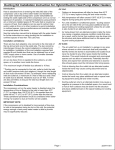
In order to meet the needs and to make clear how the system will be connected to the JRC
smart grid bus-bar as well as how the system will switch from island mode to on-grid
mode the tenders shall consider the following conception scheme:
TS-C______
p. 3/17
EUROPEAN COMMISSION
JOINT RESEARCH CENTRE
Institute for Energy and Transport
Figure 1
The supply must meet all the key technical requirements given below.
Key technical requirements for battery storage systems
A1
Chemistry: Lithium ion or equivalent, i.e. with simultaneously the same or
better levels of security, low maintenance, lifetime, peak charging and
discharging rates, power and energy density. It is up to the tenderer to fully
demonstrate such equivalence through independent, generally recognised
technical/ scientific evidences, to be mandatorily included in the technical offer.
A2
Maximum voltage: < 1000 Vdc
A3
Minimum usable capacity (on AC side): 450 kWh
A4
Support smooth automatic transition from on-grid to off-grid operation and
vice versa
A5
Able to achieve automatically synchronisation through synchrophasor
measurements when it returns back to the on-grid mode
A6
Dynamic Islanding must be supported by a micro-grid switch system as
shown in the figure above.
A7
DC breaker and protection
B1
Grid tie, 4 quadrant operation, P and Q dynamically settable
B2
3phase, 0.4kV +/- 10%, 50 Hz +/- 4%
B3
Continuous power at 25°C: 225 kW
TS-C______
p. 4/17
EUROPEAN COMMISSION
JOINT RESEARCH CENTRE
Institute for Energy and Transport
Key technical requirements for battery storage systems
B4
Peak power at 25°C, for 5 minutes: 270 kW
B5
B6
B7
B8
B9
B10
C1
C2
C3
C4
C5
C6
C7
C8
Supervision of battery charging and discharging (power limitation depending
on state of charge, coordinated action with battery EMS).
Efficiency: > 90% (at 25% of nominal power). Efficiency is interpreted in the
context of both battery charging and in battery discharging modes
Ramping capacity (P and Q): 0-100% in less than 1 second
AC breaker and protection
Connection to the Grid. Connection to and disconnection from the grid shall be
supported though a microgrid switch able to be controlled through a GUI or
SCADA.
Isolation transformer
Control Signals: select operation mode, specify set-points (P, Q, cosphi), switch
on/off battery, switch on/off converter, Disconnect from grid, synchronize to
grid
Monitoring signals: Ugrid, fgrid, Pconv, Qconv, converter state, SOC,Vbat,
Ibat, Ibatmax, battery state, alarms, AC measurement on all phases.
Dynamic active power control (P): the active power is specified according to a
set-point sent by the GUI or the SCADA. The transition time between two setpoint values must be less than 1 second. Alternatively, the active power can also
be specified as a schedule (day of week, daytime). The function parameters are
stored in the controller memory and can be changed by the GUI or the SCADA.
Dynamic reactive power control (Q): the reactive power can be specified
according to a set-point sent by the GUI or the SCADA. The transition time
between two set-point values must be less than 1 second. Alternatively, the
reactive power can also be specified as a continuous function of the injected
active power (Q= f(P)). The functions are stored in the controller memory and
can be changed by the GUI or the SCADA. Q(U) is a linear continuous function
of the reactive against the active power
Islanding Operation capability: the islanding operation must allow fixed or
variable frequency operation (frequency droops f(P)). The value of the
frequency and voltage can be changed through the GUI or the SCADA.
Low Voltage Ride Through (LVRD). The LVRT parameters shall be
adaptable in order to suit the requirements of distributed generation systems in
the different European countries. The available settings for the LVRT
parameters shall be provided in the offer.
User's Manual in English Language
Software: All software needed for the operation of the system shall be provided
in English and in the latest versions available at the time of commissioning and
must include any requirement licenses without time limitations.
TS-C______
p. 5/17
EUROPEAN COMMISSION
JOINT RESEARCH CENTRE
Institute for Energy and Transport
Key technical requirements for battery storage systems
C9
Size: Standard 20-foot container; reinforced floor able to support the
(supplied) battery system weight (maximum 3 units)
It must also support grid frequency stabilisation via virtual inertia, UPS capability
C10
C11
D1
D2
D3
D4
D5
D6
D7
D8
D9
D10
D11
D12
D13
D14
and black start.
Remote control capability (SCADA): MODbus/TCP
Outside door: Min 875/2000 mm with cylinder lock
Windows:
1x aluminium sliding window with lock
Thermal insulation: minimum 5 cm foam insulation on wall, ceiling and floor
Internal lighting:
2x fluorescent
Internal electrical plugs:
4x 16A, 230Vac on the walls
Electrical cabinet internal appliances: the electrical cabinet (3+1 phase, 16 A,
400 Vac) is supplying internal 1-phase appliances: the lights (phase 1), the AC
plugs (phase 1 and phase 2) , and the auxiliary supply of the battery converter
(phase 3). An external power supply cable (not part of the offer) will be
connected to the cabinet. The cabinet includes standard safety devices (RSD,
automatic fuses)
Connection box AC cables: an AC busbar is located in a separate connection
box inside the container. The AC cables (3-phase, 5 conductors, with double
isolation) are connected on one end to this busbar and on the other end to the
low voltage grid. The cable is not part of the offer. The box includes standard
safety devices (automatic fuses).
Connection box for communication cables: a separate connection box inside
the container is available for connecting the external communication cables.
Inside temperature control: the temperature inside the container must be
controlled (ideally by forced ventilation) to allow continuous operation of the
converter at nominal power with closed window and door, all year round
Openings for cables: enough openings must be available for the power AC, the
container power supply and the communication cables. Openings must be
available both in the lateral walls and in the floor.
Opening for maintenance: if required for maintenance, it must be possible to
easily remove the different components of the storage system out of the
container.
Painting: the inside and outside surfaces of the container must be painted in
white colour.
Mobility: the equipment inside the container must be well fixed to allow easy
transportation.
The control unit must be able to be installed inside the building in a special area;
its size cannot exceed the size of one standard container. The container(s)
hosting the batteries will be placed in a special spot, outside the building, that
can accommodate maximum two standard containers whose weight cannot
TS-C______
p. 6/17
EUROPEAN COMMISSION
JOINT RESEARCH CENTRE
Institute for Energy and Transport
Key technical requirements for battery storage systems
exceed the total of 28 tons. The limit for sustaining the container's weight is
around 2 tons per square meter. The containers hosting the batteries could be up
to 40 meters away from the control unit. See in the Annex the blueprint of the
both the building and the location dedicated to host the containers for the site of
Ispra.
D15
Min operating temp -20°C
Max operating temp 40°C
E1
Cooling power electronics: Fan forced ventilation must be provided and shall
be sufficient up to 20°C outdoor temperature. In addition, in case of higher
outdoor temperature (up to 40°C) an air-conditioning unit shall be available for
cooling.
Humidity:
< 95% non-condensing
Noise: < 85 dBA @ 2m
Enclosure:
Outdoor container
Enclosure: IP rating IP23
CE Marking or equivalent
Safety:
IEC 62103 – Electronic equipment for use in power installations
or equivalent
EMC: IEC 61000-3-4, IEC 61000-3-5 or equivalent
Warranty: 2 years including annual preventative maintenance
E2
E3
E4
E5
E6
F1
F2
F3
F4
Local on-device user interface (screen size >= 5 inch)
Explanatory and requirements details:
In islanding mode, there is no connection with grid. Islanding Capabilities can
include: Emergency Islanding Support through the battery based energy storage system,
Managing Critical/Non-Critical Loads of the experimental micro grid, and Penetrations of
Renewables.
The islanding mode of operation refers to the characteristics of the Battery Energy
Storage System controlled by components like Frequency control, inverter average
Active/Reactive Power control and charge control. The islanding mode refers to the case
when the Battery Energy System is used in coordination with the lab micro grid. Black start
refers to bidirectional flow of power, from the batteries to the micro grid and back to the
batteries. In UPS mode the flow of power is one way, usually from the grid to the batteries,
where some loads could be connected.
TS-C______
p. 7/17
EUROPEAN COMMISSION
JOINT RESEARCH CENTRE
Institute for Energy and Transport
The islanding operation shall allow fixed or variable frequency operation. This means
to have both functions – fixed and variable - but not at the same time.
The type of the container to be used for this contract is of a standard size of 20-foot.
The tenderers may use more than 1 container to achieve the purpose of the contract but no
more than 3.
The requirement for power is 225 kW (in Ispra). In order to meet this standard the
implicit rangeof P is -225kW < P < +225 kW (Ispra The requirement for the voltage is 0,4
kV. In order to meet this standard the implicit range is -400kV < Q < +400 kV. Active and
reactive power ranges shall be the same in islanding and in grid connected operations.
In islanding and in grid connected operations, the unit shall be capable to operate in
all 4 quadrants of apparent power:
1) P>0, Q>0
2) P>0, Q<0
3) P<0, Q>0
4) P<0, Q<0
F(p) is the frequency droop and Q(U) is the dynamic reactive power control.
Depending on the experiments, the reactive power of the inverter can be defined as a function
of its active power production [Q=Q(P)] or as a function of local voltage measurements
[Q=Q(U)].
Frequency droops f(P) is a linear decrease in frequency as the storage active power
goes from full charging to full discharging.
Example:
F = 50 - (P x alpha) / Prated
With:
F = frequency (48<F<52)
P = active power output
Prated = maximum active power
alpha = droop coefficient (0.5<alpha<2)
Cycles per day: an indicative target is 1 full cycle per day (1 MWh AC energy export
to grid per 24 hour).
A guarantee of twenty four (24) months is required on the whole system, starting
from the day of acceptance by the JRC, including on the 1MWh capacity
The supply shall meet the standard of the market for the metering accuracy, usually
+/- 0.1%
TS-C______
p. 8/17
EUROPEAN COMMISSION
JOINT RESEARCH CENTRE
Institute for Energy and Transport
The contract is divided into two stages:
Stage 1:
- Supply, installation, training, testing and calibration and provision of
documentation the supply within 5 months from the date of the last signature of
the contract.
- 2 year guarantee from the date of acceptance of supply and of the related services
through the Certificate of Conformity. During the period there is requested an
annual preventative maintenance for the supply.
Stage 2:
- After the end of the guarantee, preventive and corrective maintenance of the
supply for twelve months, renewable for three further years (for a total maximum
maintenance period of four years).
The detailed description of each stage is provided below:
3. STAGE 1 DOCUMENTATION AND TRAINING
1.
The full documentation related to the the supply must be provided electronically
and on paper, if requested, on the same time with the supply and must include detailed
technical specifications of all components, maintenance and service guidelines and a
comprehensive user manual covering all operation aspects of the equipment (installation,
operation, troubleshooting and maintenance of the equipment) and evidence that the
equipment was produced (manufactured) under a quality management system ISO 9001
or equivalent.
2.
The documentation and installation reports must be provided in English. All
documentation (written or drawn) submitted to JRC will be well structured and concise.
3.
The contractor must produce the deliverables related to documents in
electronic/paper format as requested by the Contracting Authority.
4.
The contractor must provide on-site 3 full days operational and service training
after installation of each supply to make clear understanding how the functionalities
works and operational parameters could be attained. Training must be conducted in
English. The dates and the detailed training programme must be mutually agreed upon
between both parties but shall be provided at the latest within 15 working days upon
request.. The estimated number of trainees for each of the training is between 3 and 8.
JRC will ensure the room and technical infrastructure for the training and the contractor
will provide the experts and the training materials. One training program will be
organized in Ispra.
TS-C______
p. 9/17
EUROPEAN COMMISSION
JOINT RESEARCH CENTRE
Institute for Energy and Transport
5.
The curriculum of the training must include at least:
a. Overview of the storage system components
b. Safety aspects
c. Operations of the storage system in grid connected mode (functions,
parameters)
d. Operations of the storage system in island connected mode (functions,
parameters)
e. Transition
between
island and
grid connected
modes
(functions, parameters)
f. Remote control and monitoring
g. Maintenance issues
4. STAGE 1 SUPPLY, INSTALLATION, CALIBRATION, TESTING AND
ACCEPTANCE
1.
The Contractor must supply, complete the assembly and install, connect of the
supply to the infrastructure/needed services, setting-to-work and commissioning of the
Battery storage systems (including the delivery of documentation and on-site training)
within 5 months from the date of the last signature of the contract. The duration does not
include the acceptance period required by JRC to confirm the compliance with the
contract and to sign the Certificate of Conformity but includes the delivery of all related
outputs.
2.
Delivery of the battery storage systems for smart grid operations must be done
within 2 months from the date of the signature of the contract by the last party.
The supply must be delivered DDP at European Commission – Joint Research Centre Institute for Energy and Transport, Ispra (Varese) Italy. The contractor has to bear the
risks and costs, including duties, taxes and other charges of delivering the good thereto.
3.
The Contractor will ensure that the various components/parts are suitably packed
to prevent accidental damage during their handling and delivery to the JRC Site (Ispra). A
written notice will be provided by the Contractor at least 7 days before the delivery of the
components/parts/equipment.
4.
After the entrance of the suply in JRC custom, installation activities must
commence on the agreed dates with JRC but not later than one month from the date of
the Commission´s written request. The contractor must install the equipment at the
premises indicated by the Commission.
TS-C______
p. 10/17
EUROPEAN COMMISSION
JOINT RESEARCH CENTRE
Institute for Energy and Transport
5.
The cabling work for connecting the equipment/system to the JRC grid will be
organized by JRC.
6.
All equipment must comply with the European and Italian regulations currently in
force and this must be certified by the contractor by providing adequate documentation
including (but not limiting to) certificates of conformity, CE markings and/or whatever
required by the relevant legislation. Compliance remains the sole responsibility of the
Contractor.
7.
The Contractor must do any remedial work and replacements necessary during
the assembly, installation, setting-to-work, calibration testing and commissioning period.
8.
The Contractor will thoroughly clean all equipment and remove all garbage, etc.,
from the working area and likewise make any necessary corrections or repair/replace
any damaged materials or equipment. Any finished surfaces that have been scratched
or discoloured shall be touched up or repainted to match the original colour. If any part
has been broken, bent, or otherwise damaged, it shall be replaced before the test.
9.
The Contractor’s personnel (and sub-contractor's personnel, if any) performing
on-site activities shall comply with all applicable Italian, site regulations, general and
specific nuclear facility regulations as defined by JRC, and any other pertinent rules,
regulations, guidelines and practices identified and communicated by JRC.
10.
Testing of the supply must take place to formally ascertain the conformity with
the present specifications within the 5 months, on days agreed by the contractor and the
JRC and with participation of the representatives of the contractor. Personnel for the
aforementioned tests must be provided by the contractor. The verification tests must serve
the purpose to ascertain that the supply is fully conforming to requirements and
specifications, including:
the check if anything is missing or appears to be damaged;
the set up and connection of the system and verification of its proper operation
and all functionalities.
11.
During the commissioning, the different functions and performance of the storage
system will be demonstrated by the contractor after JRC has connected the storage
system to its grid, including the calibration if required. The costs for the
commissioning tests must be included in this offer. During the commissioning, the
following functions will be tested:
Battery cycling test. During the test, the battery is connected to the low voltage
grid. Starting with a nearly fully charged battery (SOC >95%), the battery is
discharged at maximum current (as indicated by the battery management system)
TS-C______
p. 11/17
EUROPEAN COMMISSION
JOINT RESEARCH CENTRE
Institute for Energy and Transport
until the battery is nearly fully discharged (SOC <5%). In a second phase, the
battery is recharged at maximum current (as indicated by the battery management
system) until the battery is nearly fully charged (SOC >95%). The end of charge
and discharge, the change of maximum current must be automatically supervised
by the storage system controller. During this test, the efficiency of the converter
will also be recorded. The local and remote control and monitoring (GUI and
SCADA) will be tested.
Grid connected (parallel) operation: test of the dynamic active power control
(P) function (fixed setpoint, linear function, schedule), test of the dynamic
reactive power control (Q) function (fixed setpoint, function Q(U), function G(P))
Island operation: test of the P(f) frequency droops on a variable load profile
Personnel for the aforementioned tests shall be provided by the contractor.
12.
The contractor must demonstrate to the Commission that all operation modes,
capabilities and functions as described in the technical specifications and a complete
execution of all tasks and delivery of outputs indicated in the supplier's offer, in
conformity with the stipulated requirements. In case of a positive acceptance test result,
the Commission will sign the Certificate of Conformity for each of the supply. In case
of a negative acceptance test, the contractor must take any action necessary to pass a
second acceptance test.
13.
Acceptance will be signed by the Commission through the Certificate of
Conformity1 only after a complete execution of all tasks indicated above and
correspondingly in the contractor's offer, in conformity with the stipulated requirements.
Payment of stage 1 is conditioned to the delivery of such Certificate of Conformity2.
14.
The Contractor must ensure that Contract personnel (and any sub-Contract
personnel) performing activities on JRC site:
have the necessary ability and competence for the intended work;
are fit and healthy for undertaking the intended work;
The Contractor’s personnel (and sub-Contract personnel) performing on-site activities
services must comply with all applicable national legislation and with pertinent rules,
regulations, guidelines and practices in place in JRC-ISPRA.
1
2
As per article II.1.20 of the contract
As per article I.5 of the contract
TS-C______
p. 12/17
EUROPEAN COMMISSION
JOINT RESEARCH CENTRE
Institute for Energy and Transport
5. STAGE 1 - GUARANTEE
1. A guarantee of two years is required on the supply and its performance, starting
from the day of acceptance by the JRC (date of signing of the Certificate of
Conformity). The contractor must repair and/or replace, free of charge, any
equipment, component or part that is proven to be defective during the guarantee
period. An intervention must take place not later than 3 working days from the
call from the JRC confirmed by e-mail or fax. .
2. In maximum two (2) working days as of the date of the Commission’s request the
contractor will give technical assistance using appropriate means of
communication (e.g. by phone or e-mail).
3. The replacement of any parts will be performed after agreement with the JRC
technician in charge of the equipment who will be present during the needed
interventions.
4. All the parts replaced during the 24 months mentioned above must be covered by
the guarantee. The parts supplied must be fully compatible with the equipment
supplied and correct performance and appropriate operation must be guaranteed.
Replacement parts must be the original and certified by the manufacturer or
equivalent.
5. As soon as a loss of performance is identified, JRC will notify the Contractor who
will analyse the defect and undertake corrective action. If the corrective action is
not successfully completed within the specified time limit, the JRC may undertake
the corrective action with all consequential direct and indirect costs of JRC and its
agents to be borne by the Contractor.
6. The JRC may demand the guarantee to be extended for a period equal to that
covering the loss of performance where such loss of performance is not
attributable to JRC.
Preventive maintenance during the guarantee period:
1. The tenderer has to provide preventive maintenance at regular intervals
throughout the guarantee period in accordance with proposed Preventive
Maintenance Program for each of the supply.
TS-C______
p. 13/17
EUROPEAN COMMISSION
JOINT RESEARCH CENTRE
Institute for Energy and Transport
2. Preventive maintenance is understood as periodic intervention on the equipment
to ensure its proper function and calibration, in the absence of damage. The
preventive maintenance must take place according to the periodicity defined by
the manufacturer(s) and the manual(s) of the parts & components of the supply,
but at least once within every 12 months. The preventive maintenance must take
place on the JRC site on the initiative of the contractor after agreement between
the JRC technician in charge of the equipment and the supplier during the
working hours of the JRC.
3. This preventive maintenance must include at least:
a. Control and update of the equipment’s performance (including at least
inspection, maintenance, calibration and operational qualification of key
equipment and software updates) according to the applicable standards
including certificate(s);
b. Replacement of consumables, if required;
4. All related costs (including labour, travel and related expenses, consumables, etc.)
to the preventive maintenance must be covered by the contractor.
5. Maintenance intervention(s) shall in principle take place at the Commission
premises in site during normal working hours (Monday-Friday, 08.30 to 17.30,
excluding holidays) upon mutual agreement between both parties on the schedule
and shall be performed by the Contractor's technical staff.
A spare part is an interchangeable part that is kept in an inventory and used for the
repair or replacement of failed units. Parts that are not repairable are considered
consumable parts.
6. STAGE 2 –MAINTENANCE
Preventive maintenance after the end of the guarantee period:
1. After the end of the guarantee period, the contractor must provide preventive
maintenance according to the periodicity defined by the manufacturer(s) and the
manual(s) of the parts & components of the supply, but at least once within every
12 months. The preventive maintenance must take place on the JRC site on the
initiative of the contractor after agreement between the JRC technician in charge
of the equipment and the supplier during the working hours of the JRC.
TS-C______
p. 14/17
EUROPEAN COMMISSION
JOINT RESEARCH CENTRE
Institute for Energy and Transport
2. This preventive maintenance must include at least:
a. Control and update of the equipment’s performance (including at least
inspection, maintenance, calibration and operational qualification of key
equipment and software updates) according to the applicable standards
including certificate(s);
b. Replacement of spare parts and consumables, if required. The replacement
of consumables will be performed after agreement with the JRC technician
in charge of the equipment who will be present during the corrective
interventions.
c. All related costs (including labour, travel and related expenses,
consumables, consumables, etc.) to the preventive maintenance must be
covered by the contract.
Corrective maintenance after the end of the guarantee period:
1. The tenderer has to provide a corrective maintenance upon request (phone call
confirmed by fax or e-mail). As corrective maintenance is understood any
intervention made in case of improper performance or breakdown of the
equipment outside of the preventive maintenance. These interventions must take
place mainly at the JRC-Ispra during its working hours. If decided by JRC, the
equipment will be shipped o the supplier and be returned by the supplier to the
JRC. The transportation and related costs to transportation are to be covered by
JRC. If the transportation is required by the contractor, the transportation and
related costs are covered by the contractor.
2. The guarantee response time for the intervention must be as short as possible and
no more than 3 working days from the request.
3. The corrective maintenance must include at least:
Replacement and/or repairing of the broken/damaged components, if
required;
Replacement of spare parts and consumables, if required.
Testing and re-calibration of the equipment.
4. The replacement of any parts/consumables will be performed after agreement
with the JRC technician in charge of the equipment who will be present during the
corrective interventions.
5. The successful completion of the corrective maintenance must be done within 10
working days following the request by JRC, if this will be provided on JRC Ispra
site and within 10 working days from receipt of the equipment if the maintenance
will be provided on the contractor site. This period may be extended by the
Commission upon a duly substantiated prolongation request by the Contractor
6. The contract includes unlimited number of visits on-site for corrective
maintenance under stage 2. The contract must cover the cost related to the
corrective intervention (labour, travel to Ispra and related travel expenses)
TS-C______
p. 15/17
EUROPEAN COMMISSION
JOINT RESEARCH CENTRE
Institute for Energy and Transport
including the cost of the spare parts/components within the limit of maximum
2,000 EUR per year (based on the unit prices presented in the financial offer).
7. Agreed spare parts/components not covered in the above 2,000 EUR limit may be
the object of a separate offer to be considered for purchase by the JRC.
8. The parts supplied must be fully compatible with the instruments and the correct
performance and appropriate operation must be guaranteed.
9. Maintenance intervention(s) must in principle take place at the Commission
premises in site during normal working hours (Monday-Friday, 08.30 to 17.30,
excluding holidays) upon mutual agreement between both parties on the schedule
and must be performed by the Contractor's technical staff.
10. When deemed necessary and by mutual agreement by both parties, off-site
intervention(s) - at the sole expense of the Contractor (including shipment), hence
at no additional costs for the JRC - may take place.
7. TECHNICAL REPORTS
At the end of each intervention, both for the preventive and corrective maintenance, a
Technical Report will be produced and signed by the contractor, and countersigned by the
JRC responsible. This technical report will indicate the number of the contract, the work
performed, the time spent, and include a detailed account of the defects found and of any
parts replaced. Either the format of technical report attached in annex IV to the contract
or any other format may be used, where such other format provides for the required
information.
At the end of the each year of stage 2,, a Final Report will be produced. This final report
will indicate the number of the contract and consist of a list of all technical report/s drawn
up during the period and a copy of the countersigned Technical Report/s. This final
technical report must be approved by the JRC responsible and must condition.
This report also must describe how the stage was implemented in comparison with the
offer (annex to the contract).
All reports shall be in English and shall include the following mandatory information:
contractor, contract number, nature of the report, subject, name of the author and original
signature.
TS-C______
p. 16/17
EUROPEAN COMMISSION
JOINT RESEARCH CENTRE
Institute for Energy and Transport
8. HEALTH AND SAFETY MEASURES (OHS)
Interferential risks
During the periods of installation, guarantee or maintenance, the JRC will ensure that
where the equipment is located:
1. appropriate preventative safety measures are taken;
2. no experimental or other activity takes place, whether from JRC or other external
personnel;
As a consequence the possible interferential risks are eliminated or reduced to a level that
is not significant.
As risks may vary over the duration of the contract, any changes to interferential risks
must be communicated by the JRC to the contractor.
Before any intervention on the Ispra site the Contractor and the JRC will prepare and sign
the "Joint inspection report". This will:
1. either confirm the initial risk analysis and documentation,
2. or adapt it to new circumstances that were not foreseen, generating where
necessary either a new or an updated DUVRI ("Documento Unico di Valutazione
dei Rischi Interferenziali") or other specific document for Netherland.
The Contractor must make available the DUVRI or other specific document for
Netherland to any subcontractor and must provide the JRC with documentary evidence to
the effect that this obligation has been fulfilled.
Annex 1: Blue Print of the Building 18, which will be used to host the control unit of
the Battery Storage System.
Annex 2: Blueprint of the location outside the building 18 where the containers
hosting the batteries will be placed.
TS-C______
p. 17/17