1
battery’s voltage value. If the battery and voltage control circuitry is in working
order, the next step is to test the MCU and the sensor.
To test the MCU on this unit, the number that is going to be transmitted must be
known. The value can be printed to a computer screen for testing purposes. No
changes to the preexisting code should be made at all. That is, the code should
still transmit the number but more code can be added to instruct the MCU to also
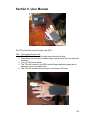
print the number to a screen. The finger sensor should be attached to one of the
design team members. A multimeter should be used to assure that current is
coming out of the photodiode. If it is not, refer to section 5.1.2. Then, the voltage
should be measured on the other side of the amplifier. If a strong voltage value
is present, the amplifier circuit is working properly.
This voltage is passed into the MCU to compute the pulse rate and SpO 2 . This
value is output to a screen and transmitted to the RDU. It is critical that this
number is medically relevant. For more information on the medical comparison,
see section 5.3.3. Since the MCU does not hold record of the voltage passed in,
it may be pertinent to measure this voltage with an oscilloscope. This assures
that the voltage is changing according to the beats of the heart. This change
allows the MCU to compute the pulse rate. For more information on how this
works, see section 2.3. Once it is guaranteed that this unit is working properly,
the RDU can be tested. The added code should be removed from the MCU
before the next step. This assures that the code flows properly and is not
constantly performing unnecessary steps. The MCU should not be cluttered with
test coding and this should all be erased before the system-level tests if possible.
The RDU is tested in a similar manner to the TSU, in that the first tests should be
on the power supplies. Since this unit has both AC power and backup batteries
this test is completed in three stages. First, the AC power should be connected.
The voltage coming in should be of the proper value. Additionally, at this point,
the batteries should not be in use. To check this, the batteries should be taken
out while the unit is on to assure that it remains powered up. Next, it should be
verified that the unit can switch between the two power supplies. When the AC is
unplugged, the unit should automatically switch to battery power without shutting
off. Then, the voltage across the battery should be tested. The battery should
have the proper voltage and be able to keep the unit turned on. Finally, the
voltage should be tested on the other side of the voltage converters in the same
manner as it was tested on the TSU. An oscilloscope should be utilized to
assure a clean DC signal is flowing into the circuit.
The MCU in the RDU should now be programmed with certain test cases to
execute. These should test the display, the indicators and the alarms in various
orders. Each has previously been tested but now must be incorporated with the
entire unit. This means that the MCU should be able to turn on the display and
switch between two different numbers while illuminating the correct indicator
LED. This is critical to the project, as the user must know which measurement is
being displayed at any moment in time. Next, each number should drop below
the threshold to assure that the alarm sounds with the proper tone at the correct
132