1
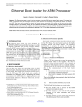
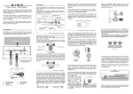
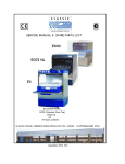
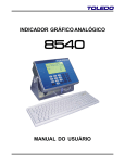
DIALighting IW19-10 Zoom Dimensions All dimensions are in millimeters Min,c/c 330 Safety Information WARNING! Read the safety precautions in this section before installing, powering, operating or servicing this product The following symbols are used to identify important safety information on the product and in this manual: DANGER! Safety hazard. Risk of severe injury or death. DANGER! Hazardous voltage. Risk of lethal or severe WARNING! Fire hazard. WARNING! LED light emission. Risk of eye injury. WARNING! Burn hazard. Hot surface. Do not touch. WARNING! Wear protective eyewear. WARNING!Refer to user manual. electric shock. Warning! Risk Group 3 (high risk) LED product according to EN 62471. Do not look into the beam ata distance of less than 8.3 meters (27 ft. 3 inches) from the front surface of the product. Do not view the light output with optical instruments or any device that may concentrate the beam. This product is for professional use only. It is not for household use. This product presents risks of severe injury or death due to fire and burn hazards, electric shock and falls. Read this manual before installing, powering or servicing the fixture, follow the safety precautions listed below and observe all warnings in this manual and printed on the fixture. If you have questions about how to operate the fixture safely, please contact your supplie PROTECTION FROM ELECTRIC SHOCK Disconnect the fixture from AC power before removing or installing any cover or part and when not in use. Always ground (earth) the fixture electrically. Use only a source of AC power that complies with local building and electrical codes and has both overload and ground-fault (earth-fault) protection. Before using the fixture, check that all power distribution equipment and cables are in perfect condition and rated for the current requirements of all connected devices. Power input and through put cables must be3-conductor, rated 20 A minimum, 1.5 mm² (16 AWG) minimum conductor size,Power input and through put cables must be3-conductor, rated 20 A minimum, 1.5 mm² (16 AWG) minimum conductor size ,exrta hard usage type(ST or equivalent). The cable must be heat-rewistant to 90° C (194° F) minimum. Use only Neutrik PowerCon NAC3FCA cable connectors to connect to power input sockets. Use only Neutrik PowerCon NAC3FCB cable connectors to connect to power throughput sockets. Isolate the fixture from power immediately if the power plug or any seal, cover, cable, or other component is damaged, defective, deformed, wet or showing signs of overheating. Do not reapply power until repairs have been completed. 3 Do not expose the fixture to rain or moisture. Refer any service operation not described in this manual to a qualified technician. Socket outlets used to supply A200 fixtures with power or external power switches must be located near the fixtures and easily accessible so that the fixtures can easily be disconnected from power. PROTECTION FROM BURNS AND FIRE Do not operate the fixture if the ambient temperature (Ta) exceeds 40° C (104° F). The exterior of the fixture becomes hot during use. Avoid contact by persons and materials. Allow the fixture to cool for at least 10 minutes before handling. Keep all combustible materials (e.g. fabric, wood, paper) at least 100 mm (3.9 in.) away from the head. Keep flammable materials well away from the fixture. Ensure that there is free and unobstructed airflow around the fixture. Do not illuminate surfaces within 200 mm (7.9 ins.) of the A200. Do not attempt to bypass thermostatic switches or fuses. If you relay power from one fixture to another using power throughput sockets, do not connect more than ten A200 fixtures in total to each other in an interconnected chain. Connect only other A200 fixtures to A200 power throughput sockets. Do not connect any other type of device to these sockets. Do not stick filters, masks or other materials onto any optical component. Do not modify the fixture in any way not described in this manual PROTECTION FROM INJURY Do not look continuously at LEDs from a distance of less than 8.3 meters (27 ft. 3 inches) from the front surface of the fixture without protective eyewear such as shade 4-5 welding goggles. At less than this distance, the LED emission can cause eye injury or irritation. At distances of 8.3 meters (27 ft. 3 inches) and above, light output is harmless to the naked eye provided that the eye’s natural aversion response is not overcome. Do not look at LEDs with magnifiers, telescopes, binoculars or similar optical instruments that may concentrate the light output. Ensure that persons are not looking at the LEDs from within 8.3 meters (27 ft. 3 inches) when the product lights up suddenly. This can happen when power is applied, when the product receives a DMX signal, or when SERVICE menu items are selected. Fasten the fixture securely to a fixed surface or structure when in use. The fixture is not portable when installed. Ensure that any supporting structure and/or hardware used can hold at least 10 times the weight of all the devices they support. If suspending from a rigging structure, fasten the fixture to a rigging clamp with an M12 bolt screwed into the threaded hole in the center of the base of the fixture. The bolt must protrude at least 20 - 30 mm (0.8 - 1.2 ins.) into the fixture. If the fixture is suspended by any other method, an M12 bolt must be tightened into this hole so that it protrudes at least 20 - 30 mm (0.8 - 1.2 ins.) into the fixture. Allow enough clearance around the head to ensure that it cannot collide with an object or another fixture when it moves. Check that all external covers and rigging hardware are securely fastened. Block access below the work area and work from a stable platform whenever installing, servicing or moving the fixture. Do not operate the fixture with missing or damaged covers, shields or any optical component. 4 Contents Dimensions . . . . . . . . . . . . . . . . . . . . . . . . . . . . . . . . . . . . . . . . . . . . . . . . . . . . . . . . . . . . . . . . . . . . . . . . 2 Safety Information . . . . . . . . . . . . . . . . . . . . . . . . . . . . . . . . . . . . . . . . . . . . . . . . . . . . . . . . . . . . . . . . . . 3 Fixture overview . . . . . . . . . . . . . . . . . . . . . . . . . . . . . . . . . . . . . . . . . . . . . . . . . . . . . . . . . . . . . . . . . . . 6 Introduction . . . . . . . . . . . . . . . . . . . . . . . . . . . . . . . . . . . . . . . . . . . . . . . . . . . . . . . . . . . . . . . . . . . . . . . . 7 Using for the first time . . . . . . . . . . . . . . . . . . . . . . . . . . . . . . . . . . . . . . . . . . . . . . . . . . . . . . . . . . . . . . . 7 AC power . . . . . . . . . . . . . . . . . . . . . . . . . . . . . . . . . . . . . . . . . . . . . . . . . . . . . . . . . . . . . . . . . . . . . . . . . . 8 Power voltage . . . . . . . . . . . . . . . . . . . . . . . . . . . . . . . . . . . . . . . . . . . . . . . . . . . . . . . . . . . . . . . . . . . . . 8 Power cables and power plug . . . . . . . . . . . . . . . . . . . . . . . . . . . . . . . . . . . . . . . . . . . . . . . . . . . . . . . . . 8 Relaying power to other devices . . . . . . . . . . . . . . . . . . . . . . . . . . . . . . . . . . . . . . . . . . . . . . . . . . . . . . . 9 Data link . . . . . . . . . . . . . . . . . . . . . . . . . . . . . . . . . . . . . . . . . . . . . . . . . . . . . . . . . . . . . . . . . . . . . . . . . . 10 Tips for reliable data transmission . . . . . . . . . . . . . . . . . . . . . . . . . . . . . . . . . . . . . . . . . . . . . . . . . . . . . 10 Connecting the data link . . . . . . . . . . . . . . . . . . . . . . . . . . . . . . . . . . . . . . . . . . . . . . . . . . . . . . . . . . . . 10 Physical installation . . . . . . . . . . . . . . . . . . . . . . . . . . . . . . . . . . . . . . . . . . . . . . . . . . . . . . . . . . . . . . . 11 Fastening the fixture to a flat surface. . . . . . . . . . . . . . . . . . . . . . . . . . . . . . . . . . . . . . . . . . . . . . . . . . . 11 Mounting the fixture on a truss . . . . . . . . . . . . . . . . . . . . . . . . . . . . . . . . . . . . . . . . . . . . . . . . . . . . . . . 11 Hanging the fixture. . . . . . . . . . . . . . . . . . . . . . . . . . . . . . . . . . . . . . . . . . . . . . . . . . . . . . . . . . . . . . . . . 12 Quick-mount surface mounting bracket . . . . . . . . . . . . . . . . . . . . . . . . . . . . . . . . . . . . . . . . . . . . . . . . . 12 Setup. . . . . . . . . . . . . . . . . . . . . . . . . . . . . . . . . . . . . . . . . . . . . . . . . . . . . . . . . . . . . . . . . . . . . . . . . . . . . 13 Control panel and menu navigation . . . . . . . . . . . . . . . . . . . . . . . . . . . . . . . . . . . . . . . . . . . . . . . . . DMX address setting . . . . . . . . . . . . . . . . . . . . . . . . . . . . . . . . . . . . . . . . . . . . . . . . . . . . . . . . . . . . Beam, Aura and FX control . . . . . . . . . . . . . . . . . . . . . . . . . . . . . . . . . . . . . . . . . . . . . . . . . . . . . . . Tailoring performance . . . . . . . . . . . . . . . . . . . . . . . . . . . . . . . . . . . . . . . . . . . . . . . . . . . . . . . . . . . Restoring factory default settings . . . . . . . . . . . . . . . . . . . . . . . . . . . . . . . . . . . . . . . . . . . . . . . . . . . . . . . . . . . . . . . . . 13 13 13 14 14 Operation and effects . . . . . . . . . . . . . . . . . . . . . . . . . . . . . . . . . . . . . . . . . . . . . . . . . . . . . . . . . . . . . 15 Effects . . . . . . . . . . . . . . . . . . . . . . . . . . . . . . . . . . . . . . . . . . . . . . . . . . . . . . . . . . . . . . . . . . . . . . . . . . 15 Service and maintenance. . . . . . . . . . . . . . . . . . . . . . . . . . . . . . . . . . . . . . . . . . . . . . . . . . . . . . . . . . 17 Cleaning. . . . . . . . . . . . . . . . . . . . . . . . . . . . . . . . . . . . . . . . . . . . . . . . . . . . . . . . . . . . . . . . . . . . . . . . . 17 Control menu service utilities. . . . . . . . . . . . . . . . . . . . . . . . . . . . . . . . . . . . . . . . . . . . . . . . . . . . . . . . . 18 DMX protocol . . . . . . . . . . . . . . . . . . . . . . . . . . . . . . . . . . . . . . . . . . . . . . . . . . . . . . . . . . . . . . . . . . . . . 19 FX: pre-programmed effects . . . . . . . . . . . . . . . . . . . . . . . . . . . . . . . . . . . . . . . . . . . . . . . . . . . . . . . 23 LEE colors and RGB equivalents . . . . . . . . . . . . . . . . . . . . . . . . . . . . . . . . . . . . . . . . . . . . . . . . . . 24 Onboard control menus. . . . . . . . . . . . . . . . . . . . . . . . . . . . . . . . . . . . . . . . . . . . . . . . . . . . . . . . . . . . 25 Display messages. . . . . . . . . . . . . . . . . . . . . . . . . . . . . . . . . . . . . . . . . . . . . . . . . . . . . . . . . . . . . . . . . 26 Specifications . . . . . . . . . . . . . . . . . . . . . . . . . . . . . . . . . . . . . . . . . . . . . . . . . . . . . . . . . . . . . . . . . . . . . 27 Fixture overview Display Control buttons AC mains power input AC mains power throughput Safety cable attachment point DMX output DMX input Note: head fan grill in production models is rotated 90° compared to this illustration. Figure 1: Fixture overview 6 Introduction This compact LED-based moving-head washlight features: Independent or linked Beam (primary LED array) and Aura (secondary background LED array) control Range of pre-programmed independent and synchronized Beam and Aura effects available via DMX that give instant access to the full potential of the fixture Beam RGBW color control with color temperature control Aura RGB control ‘Color wheel’ color snap Beam and Aura effects Onboard control panel and backlit LCD graphic display Motorized zoom Smooth electronic dimming Electronic shutter with strobe and pulse effects Calibrated and raw modes Osram Ostar high-power emitters DMX control 540° pan and 232° tilt ranges Using for the first time Warning! Read “Safety Information” on page 3 before installing, powering, operating or servicing the A200. Before applying power to the fixture: . • Carefully review “Safety Information” starting on page 3. • Check that the local AC mains power source is within the fixture’s power voltage and frequency ranges. • See “Power cables and power plug” on page 8. Install a Neutrik PowerCon NAC3FCA power input connector on a suitable power cable. If drawing power from a mains power outlet, install a suitable power plug on the power cable. 7 AC power Warning!Read “Safety Information” starting on page 3 before connecting the fixrures to AC mains power. Warning! For protection from electric shock, the A200 must be grounded (earthed). The powerdistribution circuit must be equipped with a fuse or circuit breaker and ground-fault (earth-fault)protection. Warning! Socket outlets or external power switches used to supply the A200 with power must be located near the fixture and easily accessible so that the fixtures can easily be disconnected from power. Important! Do not insert or remove live Neutrik PowerCon connectors to apply or cut power, as this may cause arcing at the terminals that will damage the connectors. Important! Do not use an external dimming system to supply power to the A200, as this may cause damage to the fixture that is not covered by the product warranty. The A200 can be hard-wired to a building electrical installation if you want to install it permanently, or a power plug that is suitable for the local power outlets can be installed on the power cable. Power voltage Warning! Check that the voltage range specified on the fixture,s serial number label matches the local AC mains power voltage before applying power to the fixture. The fixtures accept AC mains power at 100-240 V nominal, 50/60 Hz. Do not apply AC mains power to the fixture at any other voltage than that specified on the fixture’s serial number label. Power cables and power plug Power input and throughput cables must be rated 20 A minimum, have three conductors 1.5 mm² (16 AWG) minimum conductor size and an outer cable diameter of 5 - 15 mm (0.2 - 0.6 in.). Cables must be hard usage type (SJT or equivalent) and heat-resistant to 90° C (194° F) minimum. In the EU the cable must be HAR approved or equivalent. If you install a power plug on the power cable, install a grounding-type (earthed) plug that is rated 20 A minimum. Follow the plug manufacturer’s instructions. Table 1 shows standard wire color-coding schemes and some possible pin identification schemes; if pins are not clearly identified, or if you have any doubts about proper installation, consult a qualified electrician. Wire Color (EU models) Wire Color (US models) Conductor Symbol Screw (US) brown black live L yellow or brass blue white neutral N silver yellow/green green ground (earth) or Table 1: Wire color-codig and power connections 8 green Installing a power input connector on a power cable Housing Insert Chuck Bushing To install a Neutrik PowerCon NAC3FCA input connector on a power cable: 1. Slide the bushing over the cable. 2. Slide the white chuck over cables with a diameter (Da) of 5 - 10 mm (0.2 - 0.4 in.), or the black chuck over cables with a diameter of 10 15 mm (0.4 - 0.6 in.). 3. Prepare the end of the cable by stripping 20 mm (0.8 in.) of the cable’s outer jacket. Cable end 4. Strip 8 mm (1/3 in.) from the end of each of the wires. 5. Insert each of the wire ends into the appropriate terminal (see instructions and Table 1 above) and fasten the clamping device using a small flathead screw driver. 6. Push and insert the chuck into the housing (note that there is a raised key on the chuck to ensure that it is oriented correctly). 7. Fasten the bushing using a wrench to a torque of 2.5 Nm (1.8 lb.-ft). Terminals Illustrations above used by kind permission of Neutrik AG Relaying power to other devices Warning! Do not connect more than ten A200 fixtures in total to AC mains power in on einterconnected chain Power can be relayed to another device via the light-grey PowerCon throughput socket that accepts a light-grey PowerCon NAC3FCB cable connector. Note that blue input and light-grey throughput connectors have different designs: one type cannot be connected to the other. .If you link fixtures in a chain so that they all draw AC mains power via the first fixture, certain points must be respected: 2 l A hard usage, three-conductor, 16 AWG or 1.5 mm cable with SJT or equivalent cable jacket must be used to connect the first fixture to AC mains power and to interconnect all the fixtures in the chain up to a maximum of seven fixtures in total. l Light-grey Neutrik PowerCon NAC3FCB connectors must be used to draw AC mains power from the fixtures' power throughput sockets and blue Neutrik PowerCon NAC3FCA connectors must be used to supply power at the fixture's power input sockets. l No matter what the AC mains power voltage is, do not connect more than ten A200 fixtures in total(i.e. including the first fixture) to AC mains power in one interconnected daisy chain using power input and throughput connectors. 9 Data link A DMX 512 data link is required in order to control a A200 via DMX. The A200 has 3-pin XLR connectors for DMX data input and output. The pin-out on all connectors is pin 1 = shield, pin 2 = cold (-), and pin 3 = hot (+). To add more fixtures or groups of fixtures when the above limit is reached, add a DMX universe and another daisy-chained link. Tips for reliable data transmission Use shielded twisted-pair cable designed for RS-485 devices: standard microphone cable cannot transmitcontrol data reliably over long runs. 24 AWG cable is suitable for runs up to 300 meters (1000 ft). Heavier gauge cable and/or an amplifier is recommended for longer runs. Connecting the data link To connect the A200 to data: 1. Connect the DMX data output from the controller to the closest A200’s male 3-pin XLR DMX input connector. 2. Connect the DMX output of the fixture closest to the controller to the DMX input of the next fixture and continue connecting fixtures output to input. 10 Physical installation Warning! The A200 must be either fastened to a flat surface such as a stage or wall, or clamped to a truss or similar structure in any orientation using a rigging clamp. Do not apply power to the fixture if it is standing freely or the fixture can be moved. Warning! If the fixture can cause injury or damage it if falls, attach an approved safety cable to one of the safety cable attachment points on the base (see “Fixture overview” on page 6). Check that all surfaces to be illuminated are minimum 200 mm (7.9 ins.) from the fixture, that combustible materials (wood, fabric, paper, etc.) are minimum 100 mm (3.9 in.) from the head, that there is free airflow around the fixture and that there are no flammable materials nearby. Make sure that it is impossible for the moving head to collide with another fixture or other object... Fastening the fixture to a flat surface The A200 can be fastened to a fixed flat surface that is oriented at any angle. Check that the surface can support at least 10 times the weight of all fixtures and equipment to be installed on it. Warning! The supporting surface must be hard and flat or air vents in the base may be blocked, which will cause overheating. Fasten the fixture securely. Do not stand it on a surface or leave it where it can be moved or can fall over. Attach a securely anchored safety cable to the safety cable attachment point (see “Fixture overview” on page 6) if the fixture is to be installed in any location where it may fall and cause injury or damage if the primary attachment fails. Mounting the fixture on a truss The A200 can be clamped to a truss or similar rigging structure in any orientation. Warning! Use a rigging clamp with an M12 bolt if suspending the fixture from its base. The clamp must be screwed into the central threaded hole in the fixture base. The M12 bolt must protrude 20 - 30 mm (0.8 - 1.2 ins.) into the fixture base. An M12 bolt that is suitable for many types of rigging clamp is supplied with the fixture, but youmust pass the bolt through the clamp and check that the distance the bolt will protrude into the fixture base is within the 20 - 30 mm limits before using it. If the bolt is not within these limits, you must find an alternative bolt that is. To clamp a A200 to a truss: In st al lM 12 b W Se olt a e wh rni U en ng se r M su ! s an pe ua nd l! ing fix tu re . 1. Check that the rigging structure can support at least 10 times the weight of all fixtures and equipment to be installed on it. Figure 2: Rigging clamp bolt 2. Check that the rigging clamp is undamaged and can bear at least 10 times the weight of the fixture. Fasten the clamp to the fixture with a minimum grade 8.8 steel M12 bolt in the threaded hole in the center of the base of the fixture. The bolt must protrude 20 - 30 mm (0.8 - 1.2 ins.) into the base of the fixture. 11 3. Block access under the work area. Working from a stable platform, hang the fixture on the truss with the arrow on the base towards the area to be illuminated. Tighten the rigging clamp. 4. Secure the fixture against clamp failure with a secondary attachment such as an approved safety cable that is rated for the weight of the fixture using one of the attachment points at the edges of the base (see “Fixture overview” on page 6). Do not use any other part of the fixture as a safety cable attachment point. 5. Check that the head will not collide with other fixtures or objects. Hanging the fixture In some regions, it may be legal to use two safety cables, one looped through one cable attachment point (see “Fixture overview” on page 6) and the other looped through the other cable attachment point, to suspend the fixture. If one cable fails, the other will provide secondary attachment. However, this suspension method is not recommended as it will not hold the base firmly, and moving pan and tilt will cause the fixture and light beam to swing uncontrollably. Instead, we strongly recommend installation using a rigging clamp as described above. Warning! If you choose to suspend using two cables anyway, you must install a minimum 8.8 grade steel M12 bolt in the rigging clamp hole in the center of the fixture’s base. See Figure 2. The bolt must protrude 20 - 30 mm (0.8 - 1.2 ins.) into the base. If you do not secure the base in this way, there is a risk that the fixture may separate from the base and fall. Quick-mount surface mounting bracket The bracket can be screwed to a surface and the A200 mounted on and removed from the bracket in seconds. A securely anchored safety cable or other secondary attachment must be provided if the bracket is used. 12 Setup Warning! Read “Safety Information” on page 3 before installing, powering, operating or servicing the fixture. Control panel and menu navigation The onboard control panel and backlit graphic display are used to set the A200's DMX address, configure individual fixture settings (personality), read out data and execute service utilities. See “Onboard control menus” on page 25 for a complete list of menus and commands. Using the control buttons l To enter a menu, select a function or apply a selection, press ► (Enter). l Press ▲ (Up) and ▼ (Down) to scroll within a menu or adjust values. l To escape a function or move back one level in the menu structure, press ◄ (Menu / Escape). Control button reset shortcut Holding ◄(Menu/Escape) pressed in and pressing ▲ (Up) forces the fixture to reset. DMX address setting The DMX address, also known as the start channel, is the first channel used to receive instructions from the controller. For independent control, each fixture must be assigned its own control channels. Two A200 fixtures of the same type may share the same address, however, if identical behavior is desired. Address sharing can be useful for diagnostic purposes and symmetric control, particularly when combined with the inverse pan and tilt options. The DMX address is configured using the DMX ADDRESS menu in the control panel. Beam, Aura and FX control NORMAL and ADVANCED modes DMX control mode is selected in the CONTROL MODE menu. The A200 has two DMX control modes: NORMAL (normal mode – uses 14 DMX channels) ADVANCED (advanced mode – uses 25 DMX channels). NORMAL mode When the A200 is set to NORMAL standard mode, the Beam DMX channels 1 - 14 control the output of both the Beam and the A200. The behavior of the Beam and Aura are identical. Extended mode When the A200 is set to ADVANCED extended mode: Independent control of the Beam is available on channels 1 - 14 A range of FX (pre-programmed effects with combined Beam and Aura output) is available on channels 15 - 19 Independent control of the Aura is available on channels 20 - 25. See “DMX protocol” on page 19 for details of the DMX commands available in the different modes. 13 Tailoring performance Pan and tilt movement The P/T SPEED settings set the maximum speed of pan and tilt movement. FAST optimizes for speed and SLOW optimizes for smoothness of movement. NORMAL is the default setting and gives a good compromise between these two. The PAN INVERT and TILT INVERT commands reverse the direction of pan and tilt, and the SWAP command sends pan commands to tilt and vice versa. These settings are useful for symmetrical effects with multiple fixtures. Cooling FANS gives you a choice of two settings: • The default setting REGULATED should suit use in all normal situations and ensure excellent service lifetimes for all components. • FULL maximizes cooling and reduces the operating temperature of the components in the head. It is recommended when the A200 is used intensively in a warm environment or in fixed installations. Note that it will give increased fan noise compared to the other cooling modes. Whatever cooling mode is selected, a thermal cutout shuts down power to the LEDs if the fixture temperature exceeds safe limits. If this occurs, you must reset the fixture via the control menus or via DMX, or cycle power to the fixture off and on again. If a thermal shutdown occurs, you are pushing the fixture to its limits. Clean the fixture, particularly the air vents, and check that there is sufficient airflow around the fixture. Consider increasing ventilation, reducing the ambient temperature, or switching to FULL mode. Dimming Output Output Output Output DIMMER CURVE provides four dimming options (see Figure 3): DMX % DMX % DMX % DMX % Optically linear Square law Inverse square law S-curve Figure 3: Dimming curve options l LINEAR – the increase in light intensity appears to be linear as DMX value is increased. l SQUARE LAW – light intensity control is finer at low levels and coarser at high levels. l INVERSE SQUARE LAW – light intensity control is coarser at low levels and finer at high levels. l S-CURVE – light intensity control is finer at low levels and high levels and coarser at medium levels. Whichever DIMMER CURVE option you select, you can choose between FAST or SMOOTH dimming settings: l FAST is the default setting. It gives a virtually instantaneous reaction when you dim from one intensity to another, but dimming slowly from one intensity to another may appear slightly uneven. l The SMOOTH setting gives smoother dimming during slow changes in intensity, but it limits the speed of dimming changes slightly. This makes it ideal for slow, smooth dimming, but a short time-lag may be noticeable if you try to dim quickly from one intensity to another. l Restoring factory default settings The A200 factory default settings can be restored by applying a FACTORY SETTING → LOAD command. 14 Operation and effects Warning! Read “Safety Information” starting on page 3 before installing, powering, operating or servicing the A200. This section describes only DMX control features that require particular explanation. See “DMX protocols” on page 19 for a full list of the DMX channels and values required to control the different effects. Effects Beam and Aura The A200 has two LED arrays: The Beam: the LEDs that provide the main output, and The Aura: the secondary LEDs that illuminate the front of the head, provide local diffuse light output and can be set to contrast with the Beam output. See “Beam, Aura and FX control” on page 13 for full details of these modes and how to set them up. Shutter effect The electronic ‘shutter’ effect available for the Beam and the Aura provides instant open and blackout, variable speed regular and random strobe and opening/closing pulse effects as well as burst and sine wave effects. Dimming Beam and Aura intensity can be adjusted 0 - 100% using electronic dimming. See the available dimming curve options in “Dimming” on page 14 Zoom The Beam can be zoomed from 58° to maximum (narrow) 11° one-tenth peak angles. Aura output is automatically dimmed as the zoom approaches maximum. There is a linear dimming curve from normal Aura output when the Beam is at 90% zoom, to zero Aura output when the Beam is at maximum (narrow) zoom. Pan and tilt The A200’ s moving head can be panned through 540° and tilted through 232°. The speed of pan/tilt movement can be adjusted on the DMX fixture control channel 8 and in the fixture’ s onboard control panel. Both NORMAL and ADVANCED control modes offer fine control of pan and tilt. In each case, the main control channel sets the first 8 bits (the most significant byte or MSB), and the fine channel sets the second 8 bits (the least significant byte or LSB) of the 16-bit control byte. In other words, the fine channel works within the position set by the main channel. Controlling color Color wheel effects The electronic ‘color wheel’ effects available for the Beam and the Aura give the convenience and feel of a mechanical color wheel and let you snap between 33 different full LEE-referenced colors. You can also scroll continuously forwards or backwards through the colors or display random colors at variable speed. The approximate RGB equivalents of the ‘color wheel’ colors are given in “LEE colors and RGB equivalents”on page 24. Color wheel priority The color wheel effect channels for the Beam and Aura have priority and override any color set on the Beam RGBW channels or on the Aura RGB channels. To use the RGBW and RGB channels, you must set the color wheel effect channel for Beam or Aura respectively to a DMX value from 000 - 009. If you set either color wheel channel to a DMX value above 009, the color wheel effect overrides RGBW or RGB control. 15 RGBW and RGB control RGBW (in raw mode) or RGB (in calibrated mode) color control is available for the Beam and RGB control is available for the Aura. CTC (Color Temperature Control) CTC is available for the Beam on the CTC channel 14. Setting this channel to DMX value 20 or above allows you to adjust the Beam’ s overall color temperature, i.e. the color that has been set using the color wheel channel or the RGBW channels. Note that the more saturated the color, the less it will be affected by adjustments in color temperature. The biggest CTC variation is available when displaying white. Overall color temperature can be varied from 10 000-2500K.The default color temperature is 5600K. FX: pre-programmed Beam and Aura effects A library of pre-programmed effects in which Beam and Aura output can be independent or synchronized isavailable via DMX. These effects are simply called FX in this manual and in the fixture menus. The library isavailable twice in the DMX channel layout with identical functions and effects, and two different FX can be combined and run simultaneously with one ‘superimposed’ over the other. See “FX: pre-programmed effects” on page 23 for an overview of the FX available. Effects are selected using the FX select DMX channels 15 and 17. Where modification is possible, the selected FX can be modified using its FX adjust channel. Modifications can include speed, amount, offset,smoothness, etc. depending on the FX selected. FX Sync and Random operation The FX system uses a dedicated internal synchronization clock. If two different FX that repeat in cycles are activated, the FX Sync DMX channel 19 can be used to synchronize them. When two FX are synchronized,the repeat cycle of FX2 is adjusted to ensure that FX2 arrives at the end of a cycle and starts to repeat the cycle at the same time as FX1. If one FX with a short repeat cycle is combined with another FX with a long repeat cycle, the short FX can repeat twice or more in the time it takes the long FX to repeat once. But if two FX with different repeat cycles are synchronized, the short cycle is adjusted so that it arrives at the end of a cycle at the same time as the long cycle. Sync shift The sync shift option modifies FX synchronization so that FX2 runs with a time offset. This means that the FX2 cycle start point is delayed relative to FX1, but the amount of the delay remains constant. Random operation Selecting random operation makes random changes in the duration of those FX effects that have repeat cycles. This means that some cycles are shorter and some cycles are longer in a random pattern. The random sync option changes the duration of FX repeat cycles in a random pattern. Cycle duration is random, but it is always changed by the same amount for FX1 and FX2 so that FX remain synchronized. The overall speed of this synchronized effect is controlled on channel 16. The random no sync option changes the duration of FX effect cycles in a random pattern, and FX1 and FX2 are not synchronized. The speed of FX1 and FX2 effects are controlled independently on channels 16 and 18 respectively. FX priority and overriding If an FX is activated, it overrides any other settings for the parameters that the FX modifies. For example, an FX that modifies the zoom will override any zoom angle set on the zoom channel (DMX channel 3). If the same FX is selected on both the FX1 select and FX2 select channels, only the FX1 adjust channel is active. The FX2 adjust channel is ignored. If different FX are selected on the FX1 select and FX2 select channels, FX2 is superimposed onto FX1 and Fx2 overrides FX1 whenever both FX modify the same parameter. 16 Service and maintenance Warning! Read “Safety Information” on page 3 before servicing the A200. Warning! Disconnect the fixture from AC mains power and allow to cool for at least 10 minutes before handling. Do not view the light output from less than 8.3 meters (27 ft. 3 inches) without shade 4-5 welding goggles. Be prepared for the fixture to light suddenly if connected to power. Warning! Refer any service operation not described in this user manual to a qualified service technician. Important! Excessive dust, smoke fluid, and particle buildup degrades performance, causes overheating and will damage the fixture. Damage caused by inadequate cleaning or maintenance is not covered by the product warranty. It is policy to apply the strictest possible calibration procedures and use the best quality materials available to ensure optimum performance and the longest possible component lifetimes. However, LEDs are subject to wear and tear over the life of the product, resulting in gradual changes in color and overall brightness over many thousands of hours of use. The extent of wear and tear depends heavily on operating conditions and environment, so it is impossible to specify precisely whether and to what extent LED performance will be affected. However, you may eventually need to ask Professional to replace LEDs if their characteristics are affected by wear and tear after an extended period of use and if you require fixtures to perform within very precise optical and color parameters. The manufacturer’s LED lifetime data is based on performance under the manufacturer’s test conditions. As with all LEDs, the gradual reduction in luminous output will be accelerated when LEDs are used in a fixture, where conditions are much tougher than in manufacturer’s testing. To maximize LED lifetimes, keep the ambient temperature as low as possible and drive the LEDs no harder and for no longer than necessar Cleaning Cleaning schedules for lighting fixtures vary greatly depending on the operating environment. It is therefore impossible to specify precise cleaning intervals for the A200. Environmental factors that may result in a need for frequent cleaning include: • Use of smoke or fog machines. • High airflow rates (near air conditioning vents, for example). • Presence of cigarette smoke. • Airborne dust (from stage effects, building structures and fittings or the natural environment at outdoor events, for example). If one or more of these factors is present, inspect fixtures within their first 100 hours of operation to see whether cleaning is necessary. Check again at frequent intervals. This procedure will allow you to assess cleaning requirements in your particular situation. Use gentle pressure only when cleaning, and work in a clean, well-lit area. Do not use any product that contains solvents or abrasives, as these can cause surface damage. 17 Warning!Disconnect from power and allow to cool before cleaning. To clean the fixture: 1. Disconnect the fixture from power and allow it to cool for at least 10 minutes. 2. Vacuum or gently blow away dust and loose particles from the outside of the fixture and the air vents at the back and sides of the head and in the base with low-pressure compressed air. 3. Remove the central screw from the grill on the front of the head, remove the grill and clean the LED lenses by wiping gently with a soft, clean lint-free cloth moistened with a weak detergent solution. Do not rub the surface hard: lift particles off with a soft repeated press. Dry with a soft, clean, lint-free cloth or low-pressure compressed air. Remove stuck particles with an unscented tissue or cotton swab moistened with glass cleaner or distilled water. Control menu service utilities Functions test The TEST feature provides four test routines, allowing testing of pan/tilt, LEDs and display separately or together without a controller. 18 DMX protocols NORMAL ADVANCED DMX Value Percent Function 0 - 19 20 - 49 50 - 64 65 - 69 70 - 84 85 - 89 90 - 104 105 - 109 110 - 124 125 - 129 130 - 144 145 - 149 150 - 164 165 - 169 170 - 184 185 - 189 190 - 204 205 - 209 210 - 224 225 - 229 230 - 244 245 - 255 0-7 8 -19 20 - 25 26 - 27 28 - 33 34 - 35 36 - 41 42 - 43 44 - 49 50 - 51 52 - 57 58 - 59 60 - 65 66 - 67 68 - 73 74 - 75 76 - 81 82 - 83 84 - 89 90 - 91 92 - 97 98 - 100 Electronic shutter effect Shutter closed Shutter open Strobe 1 ( fast → slow ) Shutter open Strobe 2 : opening pulse ( fast → slow ) Shutter open Strobe 3 : closing pulse ( fast → slow ) Shutter open Strobe 4 : random strobe ( fast → slow ) Shutter open Strobe 5 : random opening pulse ( fast → slow ) Shutter open Strobe 6 : random closing pulse ( fast → slow ) Shutter open Strobe 7 : burst pulse ( fast → slow ) Shutter open Strobe 8 : random burst pulse ( fast → slow ) Shutter open Strobe 9 : sine wave ( fast → slow ) Shutter open Strobe 10 : burst ( fast → slow ) Shutter open 2 0 - 255 0 - 100 Beam Dimmer 0 → 100% intensity 3 0 - 255 0 - 100 Zoom Wide→narrow 4 0 - 255 0 - 100 Pan Left→right 5 0 - 255 0 - 100 Pan fine Pan fine (Least Significant Byte) 6 0 - 255 0 - 100 Tilt Tilt 0 - 232° 7 0 - 255 0 - 100 Tilt fine Tilt fine (Least Significant Byte) 0-9 10 - 14 15 - 39 40 - 44 45 - 49 50 - 54 55 - 59 60 - 64 65 - 69 70 - 74 75 - 89 90 - 94 95 - 99 100 - 104 105 - 109 110 - 114 115 - 119 120 - 124 125 - 249 250 - 255 0-3 4-5 6 - 13 14 - 15 16 - 17 18 - 19 20 - 21 22 - 23 24 - 25 26 - 27 28 - 33 34 - 35 36 - 37 38 - 40 41 - 42 43 - 44 45 - 46 47 - 48 49 - 97 98 - 100 1 8 Fixture control settings No function Reset entire fixture 1 No function PTSP = NORM 2 PTSP = FAST 2 PTSP = SLOW 2 No function Fan mode FULL 2 No function Fan mode REGULATED 2 No function Calibrated color output mode COLOR CALIB = ON 3 No function Raw color output mode COLOR CALIB = OFF 3 No function Fast dimming, speed of changes unrestricted 2 No function Smooth dimming, speed of changes restricted slightly 2 No function Illuminate display 1 If DMX Reset is disabled in the menu, a reset command can only be executed if channel 2 is set to 232 and channel 1 is setto zero. These values need to be held for 5 seconds before feature is activated. Values must be "snapped to" to function. 2 Menu override: setting unaffected by power off/on. 3 Value must be held for 3 seconds to activate. Setting unaffected by power off/on. Table 2: A200 DMX Protocol 19 DMX Value Percent 0-9 10 - 14 15 - 19 20 - 24 25 - 29 30 - 34 35 - 39 40 - 44 45 - 49 50 - 54 55 - 59 60 - 64 65 - 69 70 - 74 75 - 79 80 - 84 85 - 89 90 - 94 95 - 99 100 - 104 105 - 109 110 - 114 115 - 119 120 - 124 125 - 129 130 - 134 135 - 139 140 - 144 145 - 149 150 - 154 155 - 159 160 - 164 165 - 169 170 - 174 175 - 179 0-1 2-3 4-5 6-7 8 -9 10 - 11 12 - 13 14 - 15 16 - 17 18 - 19 20 - 21 22 - 23 24 - 25 26 - 27 28 - 29 30 - 31 32 - 33 34 - 35 36 - 37 38 - 39 40 - 41 42 - 43 44 - 45 46 - 47 48 - 49 50 - 51 52 - 53 54 - 55 56 - 57 58 - 59 60 - 61 62 - 63 64 - 65 66 - 67 68 - 69 180 - 201 202 - 207 208 - 229 230 - 234 70 - 78 79 - 80 81 - 89 90 - 91 235 - 239 240 - 244 245 - 249 250 - 255 92 - 93 94 - 95 96 - 97 98 - 100 0-255 0-100 Beam Red Red 0 → 100% 0-255 0-100 Beam Green Green 0 → 100% 0-255 0-100 Beam Blue Blue 0 → 100% 13 0-100 0-100 Beam white white 0 → 100% Note: if channel 8 is set to 90-94, this channel has no effect –white LEDs are activated by RGB mixing Color 14 0-19 20-255 0-07 8-100 Beam CCT No Function CTC 10 000K → 2 500K NORMAL ADVANCED 9 10 11 12 Function Beem Color wheel effect No function. RGBW color mixing enabled LEE 790 - Moroccan pink LEE 157 - Pink LEE 332 - Special rose pink LEE 328 - Follies pink LEE 345 - Fuchsia pink LEE 194 - Surprise pink LEE 181 - Congo Blue LEE 071 - Tokyo Blue LEE 120 - Deep Blue LEE 079 - Just Blue LEE 132 - Medium Blue LEE 200 - Double CT Blue LEE 161 - Slate Blue LEE 201 - Full CT Blue LEE 202 - Half CT Blue LEE 117 - Steel Blue LEE 353 - Lighter Blue LEE 118 - Light Blue LEE 116 - Medium Blue Green LEE 124 - Dark Green LEE 139 - Primary Green LEE 089 - Moss Green LEE 122 - Fern Green LEE 738 - JAS Green LEE 088 - Lime Green LEE 100 - Spring Yellow LEE 104 - Deep Amber LEE 179 - Chrome Orange LEE 105 - Orange LEE 021 - Gold Amber LEE 778 - Millennium Gold LEE 135 - Deep Golden Amber LEE 164 - Flame Red Open Color wheel rotation effect Clockwise, fast → slow Stop (this will stop wherever the color is at the time) Counter -clockwise, slow → fast Open Random color Fast Medium Slow Open - 15 0-255 0-100 FX1 select Pre-programmed effect 1 selection (see “FX: pre-programmed effects” on page 23) - 16 0-255 0-100 FX1 adjust, sync speed adjust Zero → maximum • If no sync set on channel 19, adjusts FX1 • If sync set on channel 19, adjusts synchronized FX1+FX2 speed - 17 0-255 0-100 FX2 select Pre-programmed effect 2 selection (see “FX: pre-programmed effects” on page 23) Table 2: A200 DMX Protocol 20 NORMAL - ADVANCED 18 - - DMX Value Percent 0 - 255 0 - 100 0-49 0-19 50-100 20-100 0-7 8-9 10 - 25 26 - 27 28 - 33 34 - 35 36 - 41 42 - 43 44 - 49 50 - 51 52 - 57 58 - 59 60 - 65 66 - 67 68 - 73 74 - 75 76 - 81 82 - 83 84 - 89 90 - 91 92 - 97 98 - 100 0 - 100 19 Function FX2 adjust Zero → maximum • If no sync set on channel 19, adjusts FX2 • If sync set on channel 19, has no effect Sync ( FX synchronization) No sync • FX1 and FX2 run through cycles independently • Cycle duration is regular • Channel 16 and channel 18 adjust FX1 and FX2 independently Sync • FX1 and FX2 run through cycles in sync • Cycle duration is regular • Channel 16 adjusts overall speed, channel 18 has no effect Aura control - 20 0 - 19 20 - 24 25 - 64 65 - 69 70 - 84 85 - 89 90 - 104 105 - 109 110 - 124 125 - 129 130 - 144 145 - 149 150 - 164 165 - 169 170 - 184 185 - 189 190 - 204 205 - 209 210 - 224 225 - 229 230 - 244 245 - 255 - 21 0 - 255 Electronic shutter effect Shutter closed Shutter open Strobe 1 ( fast → slow ) Shutter open Strobe 2 : opening pulse ( fast → slow ) Shutter open Strobe 3 : closing pulse ( fast → slow ) Shutter open Strobe 4 : random strobe ( fast → slow ) Shutter open Strobe 5 : random opening pulse ( fast → slow ) Shutter open Strobe 6 : random closing pulse ( fast → slow ) Shutter open Strobe 7 : burst pulse ( fast → slow ) Shutter open Strobe 8 : random burst pulse ( fast → slow ) Shutter open Strobe 9 : sine wave ( fast → slow ) Shutter open Strobe 10 : burst ( fast → slow ) Shutter open Aura dimmer 0 → 100% intensity Table 2: A200 DMX Protocol 21 NORMAL - ADVANCED 22 DMX Value Percent 0-9 10 - 14 15 - 19 20 - 24 25 - 29 30 - 34 35 - 39 40 - 44 45 - 49 50 - 54 55 - 59 60 - 64 65 - 69 70 - 74 75 - 79 80 - 84 85 - 89 90 - 94 95 - 99 100 - 104 105 - 109 110 - 114 115 - 119 120 - 124 125 - 129 130 - 134 135 - 139 140 - 144 145 - 149 150 - 154 155 - 159 160 - 164 165 - 169 170 - 174 175 - 179 0-1 2-3 4-5 6-7 8 -9 10 - 11 12 - 13 14 - 15 16 - 17 18 - 19 20 - 21 22 - 23 24 - 25 26 - 27 28 - 29 30 - 31 32 - 33 34 - 35 36 - 37 38 - 39 40 - 41 42 - 43 44 - 45 46 - 47 48 - 49 50 - 51 52 - 53 54 - 55 56 - 57 58 - 59 60 - 61 62 - 63 64 - 65 66 - 67 68 - 69 180 - 201 202 - 207 208 - 229 230 - 234 70 - 78 79 - 80 81 - 89 90 - 91 235 - 239 240 - 244 245 - 249 250 - 255 92 - 93 94 - 95 96 - 97 98 - 100 Function Beem Color wheel effect Open. RGBW color mixing enabled LEE 790 - Moroccan pink LEE 157 - Pink LEE 332 - Special rose pink LEE 328 - Follies pink LEE 345 - Fuchsia pink LEE 194 - Surprise pink LEE 181 - Congo Blue LEE 071 - Tokyo Blue LEE 120 - Deep Blue LEE 079 - Just Blue LEE 132 - Medium Blue LEE 200 - Double CT Blue LEE 161 - Slate Blue LEE 201 - Full CT Blue LEE 202 - Half CT Blue LEE 117 - Steel Blue LEE 353 - Lighter Blue LEE 118 - Light Blue LEE 116 - Medium Blue Green LEE 124 - Dark Green LEE 139 - Primary Green LEE 089 - Moss Green LEE 122 - Fern Green LEE 738 - JAS Green LEE 088 - Lime Green LEE 100 - Spring Yellow LEE 104 - Deep Amber LEE 179 - Chrome Orange LEE 105 - Orange LEE 021 - Gold Amber LEE 778 - Millennium Gold LEE 135 - Deep Golden Amber LEE 164 - Flame Red Open Color wheel rotation effect Clockwise, fast → slow Stop (this will stop wherever the color is at the time) Counter -clockwise, slow → fast Open Random color Fast Medium Slow Open - 23 0-255 0-100 Beam Red Red 0 → 100% - 24 0-255 0-100 Beam Green Green 0 → 100% - 25 0-255 0-100 Beam Blue Blue 0 → 100% Table 2: A200 DMX Protocol Note: DMX values labeled "No function" will have no effect - the last functional value will be used. 22 FX: pre-programmed effects The table below lists the pre-programmed effects that can be selected on DMX channels 15 and 17. Two effects can be superimposed by selecting one effect on channel 15 and a different effect on channel 17. DMX Value Percent 0-9 10 - 12 13 - 15 16 - 18 19 - 21 22 - 24 25 - 39 Function FX Adjust 0-3 4 5 6-7 8 9 10 - 15 Dimmer sync Idle Dimmer sync Strobe sync Dimmer + strobe sync Aura color sync Aura all sync Reservedl n/a n/a n/a n/a n/a n/a n/a 40 - 42 43 - 45 46 - 48 49 - 51 52 - 54 55 - 60 61 - 63 64 - 66 67 - 69 70 - 72 73 - 75 76 - 99 16 17 18 19 - 20 21 22 - 23 24 25 26 - 27 28 29 30 - 38 Aura strobe delay Aura strobe delay Strobe alternate single Strobe alternate dual Strobe alternate triple 3- step strobe Reserved Intensity random alternate Aura ramp, Beam flash Beam ramp, Aura flash Intensity Aura, Beam ramp Intensity Beam, Aura ramp Reserved Trigger Delay Speed Speed Speed Speed n/a Speed Speed Speed Speed Speed n/a Color FX 100 - 102 103 - 108 109 - 111 112 - 114 115 - 126 127 - 129 130 - 132 133 - 135 136 - 138 139 - 141 142 - 159 39 40 - 42 43 44 45 - 49 50 51 52 53 54 - 55 56 - 62 Aura color offset Aura color offset Reserved Hue shimmer Saturation shimmer Reserved Color strobe Color offset strobe Aura color strobe Aura color offset strobe Color spikes Reserved Color offset n/a Amount Amount n/a n/a Color offset on strobe n/a Aura color offset on strobe Strength n/a Zoom FX 160 - 162 163 - 165 166 - 168 169 - 171 172 - 174 175 - 177 178 - 180 181 - 219 63 64 65 66 67 - 68 69 70 71 - 85 Zoom / color offset Color zoom ramp in Color zoom ramp out Color zoom fade in Color zoom fade out Reserved Zoom ramp up Zoom ramp down Reserved Speed Speed Speed Speed n/a Speed Speed n/a Reserved 220 - 255 Reserved n/a Type Aura Sync Intensity FX 86 - 100 Table 3: FX (pre-programmed Beam and Aura effects) 23 LEE colors and RGB equivalents The table below gives approximate RGB equivalents for the LEE colors available in the standard A200’s color wheel effects for the Beam (on DMX channel 9 in NORMAL and ADVANCED modes) and Aura (on DMX channel 22 in ADVANCED mode only). DMX Integer Lee no. 24 Name Red Green Blue 790 Moroccan Pink 255 235 052 157 Pink 214 134 048 332 Special rose Pink 255 000 044 328 Follies Pink 255 059 113 345 Fuchsia Pink 255 138 219 194 Surprise Pink 226 175 226 181 Congo Blue 040 001 255 071 Tokyo Blue 000 000 255 120 Deep Blue 000 078 255 079 Just Blue 000 199 255 132 Medium Blue 000 255 234 200 Double CT Blue 149 246 255 161 State Blue 137 255 227 201 Full CT Blue 213 220 222 202 Half CT Blue 219 232 175 117 Steel Blue 205 255 199 353 Lighter Blue 115 255 165 118 Light Blue 006 255 143 116 Medium Blue Green 000 255 94 124 Dark Green 029 255 000 139 Primary Green 032 223 000 089 Moss Green 075 255 000 122 Fern Green 080 232 000 738 JAS Green 108 226 000 088 Lime Green 145 194 000 100 Spring Yellow 210 255 000 104 Deep Amber 225 232 000 179 Chrome Orange 023 215 000 105 Orange 247 214 000 021 Gold Amber 255 163 000 778 Millennium Gold 255 152 000 135 Deep Golden Amber 255 108 000 164 Flame Red 255 080 000 Onboard control menus Menu Item Options 1 - XXX DMX ADDRESS ADVANCED CONT MODE MOTOR SETTING NORMAL P/T SPEED Normal /Fast/Slow P/T SWAP NO /YES PAN INVERT TILT INVERT Normal / Reverse Normal / Reverse REGULATED FULL LINEAR SQUARE LAW INV SQUARE LAW S-CURVE OFF DIM 1/2/3/4 OFF ON ON FANS DIMMER MODE DIMMER SPEED DMX RESET PERSONALITY DISPLAY DISPLAY INTENSITY ERROR MODE INFO FACTORY SETTING Pan and tilt speed normal / fast / slow Swap pan and tilt (pan commands move tilt and vice versa) - off / on Pan inversion (reverse direction pan control) Tilt inversion (reverse direction tilt control) Cooling fan speed thermostatically regulated Max. cooling fan speed Linear dimming curve Square law dimming curve Inverse square law dimming curve 2MN S-curve dimming curve Fast dimming with unrestricted speed Smooth dimming with restricted speed Disable reset via DMX Enable reset via DMX Display is always on Display switches off and goes into Sleep mode if the controls have not been pressed for 2 minutes. 10-100 Display intensity. Default=100 NORMAL SILENT TEST Notes (Default settings in bold print) DMX address (default address = 1). The DMX address range is limited so that the fixture will always have enough DMX channels in the 512 available. Independent control of Beam and Aura, FX available (fixture uses 25 DMX channels) Linked control of Beam and Aura using Beam channels, Aura copies Beam (fixture uses 14 DMX channels) Display errors at 100% intensity (regardless of DISPLAY INTENSITY setting) and illuminate the service light Silent error mode. The error message does not appear in the display, but the service lamp is illuminated TEST ALL TEST LED TEST PAN&TILT TEST DISPLAY V1.0 VERSION Test LEDs and pan/tilt movement Test LEDs only Test pan/tilt movement only Test all segments in onboard display panel LOAD Return all settings (except calibrations) to factory defaults CPU firmware version Table 4: Control menu 25 Display messages Message Appears when... RST (Reset) ... the fixture is indexing effects at startup. Wait for reset to complete. SRST (Serial reset) ... the fixture has received a reset command. Wait for reset to complete. Note that you can set PERSONALITY → DMX RESET to OFF to prevent accidental DMX reset commands. HTSE - HEAD TMP SEN ERR ...there is a malfunction in the head temperature sensor circuit. Contact service for assistance. LTSE - LAMP TMP SEN ERROR ...there is a malfunction in the LED temperature sensor circuit. Contact service for assistance. FBEP - PAN FBACK ERR FBET - TILT FBACK ERR What to do ...there is a malfunction in the optical pan/tilt monitoring circuit (e.g. sensor defective). After Reset fixture. Contact service if a time-out, the effect in question stops in a problem continues. random position. TSER - TILT SENSOR ERR ...there is a malfunction in the electrical indexing circuit for pan, tilt or one of the drivers. Reset fixture. Contact service if problem continues. FANS - FAN ERROR ...there is a fan or fan driver error. Check that fan on rear of head is free to rotate freely. Contact service for assistance. PSER - PAN SENSOR ERR Table 5: Display messages 26 Specifications Physical Length . . . . . . . . . . . . . . . . . . . . . . . . . . . . . . . . . . . . . . . . . . . . . . . . . . . . . .305 mm (12 in.) across yoke Width . . . . . . . . . . . . . . . . . . . . . . . . . . . . . . . . . . . . . . . . . . . . . . . . . . . . . . .305 mm (12 in.) across yoke Height . . . . . . . . . . . . . . . . . . . . . . . . . . . . . . . . . . . . . . . . . . . . . . . . . .358 mm (14.1 in.), head straight up Weight . . . . . . . . . . . . . . . . . . . . . . . . . . . . . . . . . . . . . . . . . . . . . . . . 5.6 kg (12.3 lbs.) without accessories Dynamic Effects Beam color mixing . . . . . . . . . . . . . . . . . . . . . . . . . . . . . . . . . . . . . . . . . . . . . . . . . . . . . . . . . . . . . . . RGBW Aura (secondary lens array illumination) color mixing . . . . . . . . . . . . . . . . . . . . . . . . . . . . . . . . . . . . . . RGB Beam color temperature control . . . . . . . . . . . . . . . . . . . . . . . . . . . . . . . . . CTO, variable 10 000 - 2500 K Beam and Aura electronic 'color wheel' effect . . . . . . 33 LEE-referenced colors plus white, variable-speed color-wheel rotation effect and random color Beam and Aura independent shutter effects . . . . . . . . . . . . . . . . . . . . Electronic, with regular and random pulse, burst and strobe effects Pre-programmed effects . . Range of independent and synchronized Beam and Aura FX, two combinable Electronic dimming . . . . . . . . . . . . . . . . . . . . . . Independent Beam and Aura, four dimming curve options Zoom . . . . . . . . . . . . . . . . . . . . . . . . . . . . . . . . . . . . . . . . . . . . . . . . . . . . . 11° - 58° (one-tenth peak angle) Pan . . . . . . . . . . . . . . . . . . . . . . . . . . . . . . . . . . . . . . . . . . . . . . . . . . . . . . . . . . . . . . . . . . . . . . . . . . . . 540° Tilt . . . . . . . . . . . . . . . . . . . . . . . . . . . . . . . . . . . . . . . . . . . . . . . . . . . . . . . . . . . . . . . . . . . . . . . . . . . . . 232° Pan and tilt speed . . . . . . . . . . . . . . . . . . . . . . . . . . . . . . . .Adjustable via onboard control panel and DMX Optics and Photometric Data Light source . . . . . . . . . . . . . . . . . . . . . . . . . . . . . . . . . . . . . . . . 12 Osram Ostar high-power long-life emitters Total luminous output . . . . . . . . . . . . . . . . . . . . . . . . . . . . . . . . . . . . . . . 3850 lumens (zoom at maximum) Control and Programming Control options. . . . . . . . . . . . . . . . . . . . . . . . . . . . . .Independent or synchronized Beam and Aura control Control . . . . . . . . . . . . . . . . . . . . . . . . . . . . . . . . . . . . . . . . . . . . . . . . . . . . . . . . . . . . . . . . . . . . . . . . . .DMX Control resolution. . . . . . . . . . . . . . . . . . . . . . . . . . . . . . . . . . . . . . . . . .8-bit, with 16-bit control of pan & tilt DMX channels . . . . . . . . . . . . . . . . . . . . . . . . . . . . . . . . . . . . . . . . . . . . . . . . . . . . . . . . . . . . . . . . . . . 14/25 Setting and addressing . . . . . . . . . . . . . . . . . . . . . . . . . . . . . . . . Control panel with backlit graphic display Protocol . . . . . . . . . . . . . . . . . . . . . . . . . . . . . . . .. . . . . . .. . . . . . .. . . . . . . . . . . . . . . . . . . . USITT DMX512-A Construction Color . . . . . . . . . . . . . . . . . . . . . . . . . . . . . . . . . . . . . . . . . . . . . . . . . . . . . . . . . . . . . . . . . . . . . . . . . . Black Housing . . . . . . . . . . . . . . . . . . . . . . . . . . . . . . . . . . . . . . . . . . . High-impact flame-retardant thermoplastic Protection rating. . . . . . . . . . . . . . . . . . . . . . . . . . . . . . . . . . . . . . . . . . . . . . . . . . . . . . . . . . . . . . . . . . .IP 20 Installation Mounting points . . . . . . . . . . . M12 hole for rigging clamp, attachment points for surface-mounting bracket Orientation . . . . . . . . . . . . . . . . . . . . . . . . . . . . . . . . . . . . . . . . . . . . . . . . . . . . . . . . . . . . . . . . . . . . . . . .Any Minimum distance to combustible materials . . . . . . . . . . . . . . . . . . . . . . . . . . 100 mm (3.9 in.) from fixture Minimum distance to illuminated surfaces . . . . . . . . . . . . . . . . . . . . . . . . . . . 200 mm (7.9 ins.) from fixture Location . . . . . . . . . . . . . . . . . . . . . . . . . . . . . . . .Indoor use only, must be fastened to structure or surface Connections AC power input . . . . . . . . . . . . . . . . . . . . . . . . . . . . . . . .Neutrik PowerCon NAC3MPA input socket (blue) AC power throughput. . . . . . . . . . . . . . . . . . . . . . . . . . .Neutrik PowerCon NAC3MPB output socket (grey) DMX data in/out . . . . . . . . . . . . . . . . . . . . . . . . . . . . . . . . . . . . . . . . . . . . . . . . . . . . . . . . .3-pin locking XLR 27 Electrical AC power . . . . . . . . . . . . .. . . . . . . . . . . . . . 100-240 V nominal, 50/60 Hz Maximum total power consumption . . . . . . . . . . . . . . . . . . . . . . . . . .260 W Power supply unit . . . . . . . . . . . . . . . . . . . .Auto-ranging electronic switch mode Power consumption, all effects static, zero light output . . . . . . . . . . . . . . . . <15 W Typical Power and Current 100 120 208 230 240 V, V, V, V, V, 60 60 60 50 50 Hz Hz Hz Hz Hz . . . . . . . . . . . . . . . . . . . . . . . . . . . . . . . . . . . . . . . . . . . . . . . . . . . . . . . . . . . . . . . . . . . . . . . . . . . . . . . . . . . . . . . . . . . . . . . . . . . . . . . . . . . . . . . . . . . . . . . . . . . . . . . . . . . . . . 236 234 229 228 228 W, W, W, W, W, 2.4 2.0 1.2 1.1 1.0 A, A, A, A, A, PF PF PF PF PF 0.994 0.992 0.970 0.959 0.953 PF = power factor. Measurements made at nominal voltage with all LEDs at full intensity. Allow for a deviation of +/- 10%. Thermal Cooling. . . . . . . . . Forced air (temperature-regulated, low noise, user-definable levels) Maximum ambient temperature (Ta max.). . .. . . . . . . . . . . . . . . 40° C (104° F) Minimum ambient temperature (Ta min.). . . . . . . . . . . . . . . . . . . 5° C (41° F) Total heat dissipation (calculated, +/- 10%). . . . . . . . . . . . . . . . . . . . 820 BTU/hr. 28