1
Preface
Thank you for choosing DELTA’s high-performance VFD-M-D Series. The VFD-M-D Series is
manufactured with high-quality components and materials and incorporate the latest microprocessor
technology available.
This manual is to be used for the installation, parameter setting, troubleshooting, and daily
maintenance of the AC motor drive. To guarantee safe operation of the equipment, read the following
safety guidelines before connecting power to the AC motor drive. Keep this operating manual at hand
and distribute to all users for reference.
To ensure the safety of operators and equipment, only qualified personnel familiar with AC motor
drive are to do installation, start-up and maintenance. Always read this manual thoroughly before
using VFD-M-D series AC Motor Drive, especially the WARNING, DANGER and CAUTION notes.
Failure to comply may result in personal injury and equipment damage. If you have any questions,
please contact your dealer.
PLEASE READ PRIOR TO INSTALLATION FOR SAFETY.
DANGER!
1.
Ensure that VFD-M-D is grounded in a correct way before putting it into use.
2.
AC input power must be disconnected before any wiring to the AC motor drive is made.
3.
A charge may still remain in the DC-link capacitors with hazardous voltages, even if the power
has been turned off. To prevent personal injury, please ensure that power has been turned off
before opening the AC motor drive and wait ten minutes for the capacitors to discharge to safe
voltage levels.
4.
Never reassemble internal components or wiring.
5.
The AC motor drive may be destroyed beyond repair if incorrect cables are connected to the
input/output terminals. Never connect the AC motor drive output terminals U/T1, V/T2, and
W/T3 directly to the AC mains circuit power supply.
6.
Ground the VFD-M-D using the ground terminal. The grounding method must comply with the
laws of the country where the AC motor drive is to be installed. Refer to the Basic Wiring
Diagram.
7.
VFD-M-D series is used only to control variable speed of 3-phase induction motors, NOT for 1phase motors or other purpose.
8.
VFD-M-D series is the specific drive for the elevator door and other automatic door control,
NOT for those devices that may cause personal injury, such as life support equipment or any
life safety situation.
9.
VFD-M-D is produced with strict quality management. It will need the safety device when it is
used in those occasions that may cause severe accident due to the malfunction.
WARNING!
1.
DO NOT use Hi-pot test for internal components. The semi-conductor used in the AC motor
drive is easily damaged by high-pressure.
2.
There are highly sensitive MOS components on the printed circuit boards. These components
are especially sensitive to static electricity. To prevent damage to these components, do not
touch these components or the circuit boards with metal objects or your bare hands.
3.
Only quality person is allowed to install, wire and maintain AC motor drive.
CAUTION!
1.
Some parameter settings will cause the motor to run immediately after applying power.
2.
DO NOT install the AC motor drive in a place subjected to high temperature, direct sunlight,
high humidity, excessive vibration, corrosive gases or liquids, or airborne dust or metallic
particles.
3.
Only use AC motor drives within specification. Failure to comply may result in fire, explosion or
electric shock.
4.
To prevent personal injury, please keep children and unqualified people away from the
equipment.
5.
When the motor cable between the AC motor drive and motor is too long, the layer insulation of
the motor may be damaged. Please use a frequency inverter duty motor or add an AC output
reactor to prevent damage to the motor. Refer to appendix B Reactor for details.
6.
The rated voltage for the AC motor drive must be ≤ 240V and the mains supply current capacity
must be ≤ 5000A RMS.
Table of Contents
Preface ............................................................................................................. i
Table of Contents .......................................................................................... iii
Chapter 1 Introduction ................................................................................ 1-1
1.1 Receiving and Inspection ................................................................... 1-2
1.1.1 Nameplate Information................................................................ 1-2
1.1.2 Model Explanation ...................................................................... 1-2
1.1.3 Series Number Explanation ........................................................ 1-3
1.1.4 Appearances............................................................................... 1-3
1.1.5 Remove Instructions ................................................................... 1-4
1.2 Preparation for Installation and Wiring ............................................... 1-5
1.2.1 Ambient Conditions..................................................................... 1-5
1.2.2 Minimum Mounting Clearance .................................................... 1-6
1.3 Dimensions......................................................................................... 1-8
Chapter 2 Wiring.......................................................................................... 2-1
2.1 Basic Wiring Diagrams ....................................................................... 2-2
2.2 External Wiring ................................................................................... 2-6
2.3 Main Circuit ........................................................................................ 2-7
2.3.1 Main Terminals Connections ...................................................... 2-7
2.3.2 Main Circuit Terminals ................................................................ 2-9
2.4 Control Circuit................................................................................... 2-10
2.4.1 Circuit diagram for digital inputs (NPN mode) ........................... 2-10
2.4.2 Control Terminals ...................................................................... 2-13
Chapter 3 Keypad and Start Up ..................................................................3-1
3.1 Keypad ...............................................................................................3-1
3.1.1 Description of the Digital Keypad LC-M2E .................................. 3-1
3.1.2 How to Operate the Digital Keypad LC-M2E ............................... 3-2
3.1.3 LC-M2E ....................................................................................... 3-3
3.2 Preparations before Start-up...............................................................3-4
3.3 Operation Method ...............................................................................3-5
3.4 Trial Run .............................................................................................3-5
Chapter 4 Parameters..................................................................................4-1
4.1 Summary of Parameter Settings.........................................................4-2
4.2 Description of Parameter Settings ....................................................4-14
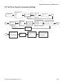
4.3 The Flow Chart for Parameter Settings ............................................4-89
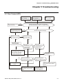
Chapter 5 Troubleshooting .........................................................................5-1
5.1 Over Current (OC) ..............................................................................5-1
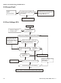
5.2 Ground Fault.......................................................................................5-2
5.3 Over Voltage (OV) ..............................................................................5-2
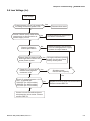
5.4 Low Voltage (Lv).................................................................................5-3
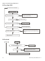
5.5 Over Heat (OH)...................................................................................5-4
5.6 Overload .............................................................................................5-4
5.7 Display of LC-M2E is Abnormal ..........................................................5-5
5.8 Phase Loss (PHL)...............................................................................5-5
5.9 Motor cannot Run ...............................................................................5-6
5.10 Motor Speed cannot be Changed .....................................................5-7
5.11 Motor Stalls during Acceleration....................................................... 5-8
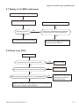
5.12 The Motor does not Run as Expected .............................................. 5-8
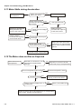
5.13 Electromagnetic/Induction Noise ...................................................... 5-9
5.14 Environmental Condition .................................................................. 5-9
5.15 Affecting Other Machines ............................................................... 5-10
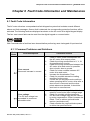
Chapter 6 Fault Code Information and Maintenance................................ 6-1
6.1 Fault Code Information ....................................................................... 6-1
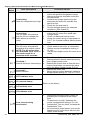
6.1.1 Common Problems and Solutions............................................... 6-1
6.1.2 Reset .......................................................................................... 6-4
6.2 Maintenance and Inspections............................................................. 6-5
Appendix A Specifications ........................................................................ A-1
Appendix B Accessories ........................................................................... B-1
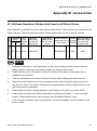
B.1 All Brake Resistors & Brake Units Used in AC Motor Drives..............B-1
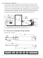
B.1.1 Dimensions and Weights for Brake Resistors ............................ B-2
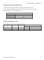
B.2 Non-fuse Circuit Breaker Chart ..........................................................B-3
B.3 Fuse Specification Chart ....................................................................B-3
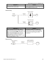
B.4 Reactor ..............................................................................................B-4
B.4.1 AC Reactor ................................................................................. B-4
B.4.2 Zero Phase Reactor (RF220X00A)............................................. B-6
B.5 VFD-PU06..........................................................................................B-7
B.5.1 Description of the Digital keypad VFD-PU06 .............................. B-7
B.5.2 Explanation of Display Message................................................. B-7
B.5.3 VFD-PU06 Operation Flow Chart ............................................... B-8
B.6 AMD - EMI Filter Cross Reference.....................................................B-9
B.6.1 Dimensions............................................................................... B-12
v
Appendix C How to Select the Right AC Motor Drive .............................. C-1
C.1 Capacity Formulas ............................................................................ C-2
C.2 General Precaution ........................................................................... C-4
C.3 How to Choose a Suitable Motor....................................................... C-5
Chapter 1 Introduction|VFD-M-D Series
Chapter 1 Introduction
The AC motor drive should be kept in the shipping carton or crate before installation. In order to retain
the warranty coverage, the AC motor drive should be stored properly when it is not to be used for an
extended period of time. Storage conditions are:
Store in a clean and dry location free from direct sunlight or corrosive fumes.
Store within an ambient temperature range of -20 °C to +60 °C.
Store within a relative humidity range of 0% to 90% and non-condensing environment.
Store within an air pressure range of 86kPA to 106kPA.
CAUTION!
1.
DO NOT store in an area with rapid changes in temperature. It may cause condensation and
frost.
2.
DO NOT place on the ground directly. It should be stored properly. Moreover, if the surrounding
environment is humid, you should put exsiccator in the package.
3.
If the AC motor drive is stored for more than 3 months, the temperature should not be higher
than 30 °C. Storage longer than one year is not recommended, it could result in the degradation
of the electrolytic capacitors.
4.
When the AC motor drive is not used for a long time after installation on building sites or places
with humidity and dust, it’s best to move the AC motor drive to an environment as stated above.
Revision May 2009, MDE5, SW V1.1
1-1
Chapter 1 Introduction|VFD-M-D Series
1.1 Receiving and Inspection
This VFD-M-D AC motor drive has gone through rigorous quality control tests at the factory before
shipment. After receiving the AC motor drive, please check for the following:
Check to make sure that the package includes an AC motor drive, the User Manual/Quick Start
and CD, dust covers and rubber bushings.
Inspect the unit to assure it was not damaged during shipment.
Make sure that the part number indicated on the nameplate corresponds with the part number
of your order.
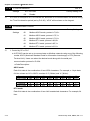
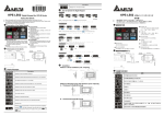
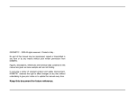
1.1.1 Nameplate Information
Example for 0.5HP/0.4kW 230V 1-Phase 230V AC motor drive
AC Drive Model
Input Spec.
Output Spec.
Output Frequency Range
MODEL : VFD004M21B-D
IN PU T : 1 PH 6 .3 A/3 PH 3 .2A 2 00-24 0V 50 / 60 Hz
O UTPU T : 3PH 0 -2 40 V 2.5A 1.0 kVA 0 .5 HP
FR E QU EN C Y R AN GE : 0 .1-40 0Hz
Serial Number & Bar Code
004M21BDT5220001
Software version
01.02
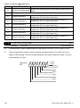
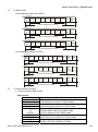
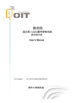
1.1.2 Model Explanation
VFD 004 M 21 B - D
Specific AC Motor Drives
for Elevator Door
Version Type
Mains Input Voltage
21: 230V Single phase
M Series
Applicable motor capacity
004: 0.5 HP(0.4kW)
Series Name ( V ariable F requency D rive)
1-2
Revision May 2009, MDE5, SW V1.1
Chapter 1 Introduction|VFD-M-D Series
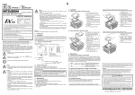
1.1.3 Series Number Explanation
004M21BD T 6 22 0001
Production number
Production week
Production year 2006
Production factory
230V 1-phase 0.5HP(0.4kW)
(Taoyuan)
Model
If the nameplate information does not correspond to your purchase order or if there are
any problems, please contact your distributor.
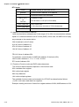
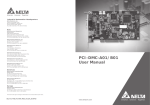
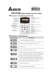
1.1.4 Appearances
VFD004M21B-D
Revision May 2009, MDE5, SW V1.1
1-3
Chapter 1 Introduction|VFD-M-D Series
VFD004M21W-D
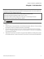
1.1.5 Remove Instructions
Remove Keypad
1-4
Revision May 2009, MDE5, SW V1.1
Chapter 1 Introduction|VFD-M-D Series
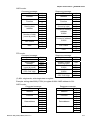
Remove Front Cover
RST Side
UVW Side
1.2 Preparation for Installation and Wiring
1.2.1 Ambient Conditions
Install the AC motor drive in an environment with the following conditions:
Operation
Air Temperature:
-10 ~ +50°C (14 ~ 122°F) for UL & cUL
Relative Humidity:
<90%, no condensation allowed
Atmosphere pressure: 86 ~ 106 kPa
Installation Site Altitude: <1000m
Vibration:
<20Hz: 9.80 m/s2 (1G) max
20 ~ 50Hz: 5.88 m/s2 (0.6G) max
Storage
Transportation
Temperature:
Relative Humidity:
Atmosphere pressure:
Vibration:
-20°C ~ +60°C (-4°F ~ 140°F)
<90%, no condensation allowed
86 ~ 106 kPa
<20Hz: 9.80 m/s2 (1G) max
20 ~ 50Hz: 5.88 m/s2 (0.6G) max
Pollution Degree 2: good for a factory type environment.
CAUTION!
1.
Operating, storing or transporting the AC motor drive outside these conditions may cause
damage to the AC motor drive.
2.
Failure to observe these precautions may void the warranty!
Revision May 2009, MDE5, SW V1.1
1-5
Chapter 1 Introduction|VFD-M-D Series
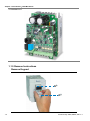
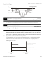
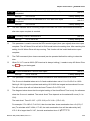
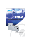
1.2.2 Minimum Mounting Clearance
15 0mm
50 mm
5 0mm
15 0mm
Air Flow
CAUTION!
1.
Mount the AC motor drive vertically on a flat vertical surface by using bolts or screws.
Other directions are not allowed.
2.
The AC motor drive will generate heat during operation. Allow sufficient space around the
unit for heat dissipation.
3.
The heat sink temperature may rise to 90°C when running. The material on which the AC
motor drive is mounted must be noncombustible and be able to withstand this high
temperature.
4.
When the AC motor drive is installed in a confined space (e.g. cabinet), the surrounding
temperature must be within 10 ~ 40°C with good ventilation. DO NOT install the AC motor
drive in a space with bad ventilation.
5.
Prevent fiber particles, scraps of paper, saw dust, metal particles, etc. from adhering to
the heatsink.
6.
When installing multiple AC motor drives in the same cabinet, they should be adjacent in
a row with enough space in-between. When installing one AC motor drive below another
one, use a metal separation barrier between the AC motor drives to prevent mutual
heating.
1-6
Revision May 2009, MDE5, SW V1.1
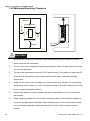
Chapter 1 Introduction|VFD-M-D Series
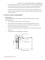
Installation with Metal Separation
150mm
Installation without Metal Separation
150mm
B
150mm
B
Air Flow
150mm
150mm
150mm
Side View
Revision May 2009, MDE5, SW V1.1
1-7
Chapter 1 Introduction|VFD-M-D Series
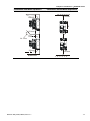
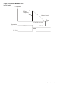
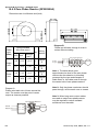
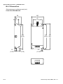
1.3 Dimensions
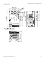
(Dimensions are in millimeter and [inch])
VFD004M21B-D
1-8
Revision May 2009, MDE5, SW V1.1
Chapter 1 Introduction|VFD-M-D Series
VFD004M21W-D
Revision May 2009, MDE5, SW V1.1
1-9
Chapter 1 Introduction|VFD-M-D Series
This page intentionally left blank.
1-10
Revision May 2009, MDE5, SW V1.1
Chapter 2 Wiring|VFD-M-D Series
Chapter 2 Wiring
After removing the front cover, check if the power and control terminals are clear of debris. Be sure to
observe the following precautions when wiring.
General Wiring Information
Applicable Codes
All VFD-M-D series except VFD004M21W-D are Underwriters Laboratories, Inc. (UL) and
Canadian Underwriters Laboratories (cUL) listed, and therefore comply with the requirements of
the National Electrical Code (NEC) and the Canadian Electrical Code (CEC).
Installation intended to meet the UL and cUL requirements must follow the instructions provided
in “Wiring Notes” as a minimum standard. Follow all local codes that exceed UL and cUL
requirements. Refer to the technical data label affixed to the AC motor drive and the motor
nameplate for electrical data.
The "Line Fuse Specification" in Appendix B, lists the recommended fuse part number for each
VFD-M-D series part number. These fuses (or equivalent) must be used on all installations
where compliance with U.L. standards is a required.
NOTE
VFD004M21W-D has no approvals.
CAUTION!
Make sure that power is only applied to the R/L1, S/L2, T/L3 terminals. Failure to comply may
result in damage to the equipment. The voltage and current should lie within the range as
indicated on the nameplate.
Check the following items after completing the wiring:
1. Are all connections correct?
2. No loose wires?
3. No short-circuits between terminals or to ground?
A charge may still remain in the DC bus capacitors with hazardous voltages even if the power
has been turned off. To prevent personal injury, please ensure that the power is turned off and
wait ten minutes for the capacitors to discharge to safe voltage levels before opening the AC
motor drive.
Revision May 2009, MDE5, SW V1.1
2-1
Chapter 2 Wiring|VFD-M-D Series
DANGER!
1.
All the units must be grounded directly to a common ground terminal to prevent electric shock,
fire and interference.
2.
Only qualified personnel familiar with AC motor drives are allowed to perform installation, wiring
and commissioning.
3.
Make sure that the power is off before doing any wiring to prevent electric shocks.
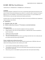
2.1 Basic Wiring Diagrams
Users must connect wires according to the circuit diagrams on the following pages. Do not plug a
modem or telephone line to the RS-485 communication port or permanent damage may result.
Terminals 1 & 2 are the power supply for the optional copy keypad PU06 only and should not be used
for RS-485 communication.
2-2
Revision May 2009, MDE5, SW V1.1
Chapter 2 Wiring|VFD-M-D Series
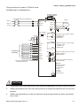
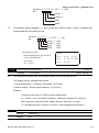
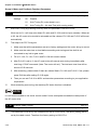
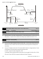
The figure below for models of VFD-M-D series
VFD004M21B-D; VFD004M21W-D
Fuse/NFB(None Fuse Breaker)
R(L1)
B2
U(T1)
R(L1)
S(L2)
S(L2)
T(L3)
T(L3)
V(T2)
W(T3)
M otor
IM
3~
E
RA1
VP Voltage
24V
12V
+12/24V
PG A
B
GN D
Force stop
Em ergency stop
Door open limit signal
Factory
setting
Door close limit signal
Demo mode
FWD/STO P
REV/STOP
Digital Signal Common
* Don't apply the mains voltage directly
to above terminals.
RB1
VP
RC1
A
B
M ulti-function contact output
240VAC 2.5A
120VAC 5A
24VDC 5A
RA2
DCM
M I1
M I2
RC2
M ulti-function contact output
240VAC 2.5A
120VAC 5A
24VDC 5A
M I3
M I4
Mo1
output of multi-function contact
(open collector)
48VDC50mA
M I5
FWD
REV
Mo2
DCM
MCM
6 ←1
Common o utput ter minal of
photocoupler
RS-485
Serial interface
1: Reserved
2: Reserved
3: SG 4: SG +
5:NON E
6: R eserved
CAUTION!
1.
2.
The wiring of main circuit and control circuit should be separated to prevent erroneous actions.
Please use shield wire for the control wiring and not to expose the peeled-off net in front of the
terminal.
3.
Please use the shield wire or tube for the power wiring and ground the two ends of the shield
wire or tube.
Revision May 2009, MDE5, SW V1.1
2-3
Chapter 2 Wiring|VFD-M-D Series
4.
Damaged insulation of wiring may cause personal injury or damage to circuits/equipment if it
comes in contact with high voltage.
5.
The AC motor drive, motor and wiring may cause interference. To prevent the equipment
damage, please take care of the erroneous actions of the surrounding sensors and the
equipment.
6.
When the AC drive output terminals U/T1, V/T2, and W/T3 are connected to the motor terminals
U/T1, V/T2, and W/T3, respectively. To permanently reverse the direction of motor rotation,
switch over any of the two motor leads.
7.
With long motor cables, high capacitive switching current peaks can cause over-current, high
leakage current or lower current readout accuracy. To prevent this, the motor cable should be
less than 20m for 3.7kW models and below. And the cable should be less than 50m for 5.5kW
models and above. For longer motor cables use an AC output reactor.
8.
The AC motor drive, electric welding machine and the greater horsepower motor should be
grounded separately.
9.
10.
Use ground leads that comply with local regulations and keep them as short as possible.
No brake resistor is built in the VFD-M-D series, it can install brake resistor for those occasions
that use higher load inertia or frequent start/stop. Refer to Appendix B for details.
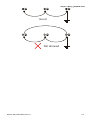
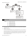
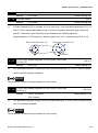
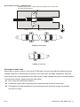
11.
Multiple VFD-M-D units can be installed in one location. All the units should be grounded
directly to a common ground terminal, as shown in the figure below. Ensure there are no
ground loops.
Excellent
2-4
Revision May 2009, MDE5, SW V1.1
Chapter 2 Wiring|VFD-M-D Series
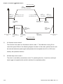
Good
Not allowed
Revision May 2009, MDE5, SW V1.1
2-5
Chapter 2 Wiring|VFD-M-D Series
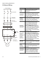
2.2 External Wiring
Items
Power Supply
Power
supply
Fuse/NFB
(Optional)
There may be an inrush current
during power up. Please check the
chart of Appendix B and select the
correct fuse with rated current. Use of
an NFB is optional.
Magnetic
contactor
(Optional)
Please do not use a Magnetic
contactor as the I/O switch of the AC
motor drive, as it will reduce the
operating life cycle of the AC drive.
FUSE/NFB
Magnetic
contactor
Input AC
Line Reactor
EMI Filter
R/L1
S/L2
T/L3
B1
Braking
Resistor
B2
U/T1
V/T2
W/T3
Zero-phase
Reactor
Output AC
Line Reactor
Motor
Explanations
Please follow the specific power
supply requirements shown in
Appendix A.
Used to improve the input power
factor, to reduce harmonics and
provide protection from AC line
disturbances. (surges, switching
Input AC
spikes, short interruptions, etc.). AC
Line Reactor
line reactor should be installed when
(Optional)
the power supply capacity is 500kVA
or more and exceeds 6 times the
inverter capacity, or the mains wiring
distance ≤ 10m.
Zero-phase
Reactor
(Ferrite Core
Common
Choke)
(Optional)
Zero phase reactors are used to
reduce radio noise especially when
audio equipment is installed near the
inverter. Effective for noise reduction
on both the input and output sides.
Attenuation quality is good for a wide
range from AM band to 10MHz.
Appendix B specifies the zero phase
reactor. (RF220X00A)
EMI filter
(Optional)
To reduce electromagnetic
interference, please refer to Appendix
B for more details.
Brake
Resistor
(Optional)
Used to reduce the deceleration time
of the motor. Please refer to the chart
in Appendix B for specific Brake
Resistors.
Motor surge voltage amplitude
Output AC
depends on motor cable length. For
Line Reactor
applications with long motor cable
(Optional)
(>20m), it is necessary to install a
reactor at the inverter output side.
2-6
Revision May 2009, MDE5, SW V1.1
Chapter 2 Wiring|VFD-M-D Series
2.3 Main Circuit
2.3.1 Main Terminals Connections
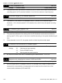
The figure below for models of VFD-M-D series
VFD004M21B-D; VFD004M21W-D
Braking Resistor (Optional)
BR
Non-fuse breaker
( NFB )
MC
R
S
T
B1
R(L1)
S(L2)
T(L3)
E
Terminal Symbol
B2
U(T1)
V(T2)
Motor
W(T3)
E
Explanation of Terminal Function
R/L1, S/L2, T/L3
AC line input terminals (1-phase/3-phase)
U/T1, V/T2, W/T3
AC drive output terminals for connecting 3-phase
induction motor
B1, B2
IM
3~
Connections for Brake Resistor (optional)
Earth connection, please comply with local regulations.
CAUTION!
Mains power terminals (R/L1, S/L2, T/L3)
Connect these terminals (R/L1, S/L2, T/L3) via a non-fuse breaker or earth leakage
breaker to 3-phase AC power (some models to 1-phase AC power) for circuit protection. It
is unnecessary to consider phase-sequence.
It is recommended to add a magnetic contactor (MC) in the power input wiring to cut off
power quickly and reduce malfunction when activating the protection function of AC motor
drives. Both ends of the MC should have an R-C surge absorber.
Please make sure to fasten the screw of the main circuit terminals to prevent sparks which
Please use voltage and current within the regulation shown in Appendix A.
is made by the loose screws due to vibration.
Revision May 2009, MDE5, SW V1.1
2-7
Chapter 2 Wiring|VFD-M-D Series
When using a GFCI (Ground Fault Circuit Interrupter), select a current sensor with
sensitivity of 200mA, and not less than 0.1-second detection time to avoid nuisance
tripping.
Output terminals for main circuit (U, V, W)
When it needs to install the filter at the output side of terminals U/T1, V/T2, W/T3 on the
AC motor drive. Please use inductance filter. Do not use phase-compensation capacitors
or L-C (Inductance-Capacitance) or R-C (Resistance-Capacitance), unless approved by
Delta.
DO NOT connect phase-compensation capacitors or surge absorbers at the output
Use a well-insulated motor, suitable for inverter operation.
When using a GFCI (Ground Fault Circuit Interrupter), select a current sensor with
terminals of AC motor drives.
sensitivity of 200mA, and not less than 0.1-second detection time to avoid nuisance
tripping.
Terminals [B1, B2] for connecting external brake unit
Braking resistor(optional)
Refer to Appendix B for the use of
special braking resistor
BR
B2
Connect a brake resistor or brake unit in applications with frequent deceleration ramps,
The AC motor drive has a built-in brake chopper, you can connect the external brake
When not used, please leave the terminals [B1, B2] open.
short deceleration time, too low brake torque or requiring increased brake torque.
resistor to the terminals [B1, B2] when needed.
2-8
Revision May 2009, MDE5, SW V1.1
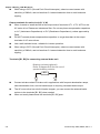
Chapter 2 Wiring|VFD-M-D Series
Frame
Power Terminals
W/T3
V/T2
U/T1
N/L2
L/L1
2.3.2 Main Circuit Terminals
Torque
Wire Gauge
Wire Type
14kgf-cm
12-14 AWG.
(3.3-2.1mm2)
Copper only, 75℃
R/L1, S/L2, T/L3 (M-D)
L/L1, N/L2 (W-D)
A
(12in-lbf)
U/T1, V/T2, W/T3,
NOTE
Frame A: VFD004M21B-D; VFD004M21W-D
Revision May 2009, MDE5, SW V1.1
2-9
Chapter 2 Wiring|VFD-M-D Series
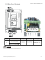
2.4 Control Circuit
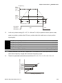
2.4.1 Circuit diagram for digital inputs (NPN mode)
NPN Mode
+24
multi-input
terminal
DCM
Internal Circuit
Terminal symbols and functions
Terminal
Symbol
FWD
Forward-Stop command
REV
Reverse-Stop command
MI1
Multi-function Input 1
MI2
Multi-function Input 2
MI3
Multi-function Input 3
MI4
Multi-function Input 4
MI5
Multi-function Input 5
DCM
Digital Signal Common
A
A-phase Input Terminal
B
B-phase Input Terminal
VP
2-10
Factory Settings
Terminal Function
+12/24 Vdc Output
ON: Connect to DCM
ON:
Run in FWD direction (door close)
OFF:
Stop acc. to Stop Method
ON:
Run in REV direction (door open)
OFF:
Stop acc. to Stop Method
Refer to Pr.5-00 to Pr.5-04 for programming the
Multi-function Inputs.
ON: the activation current is 16mA.
OFF: leakage current tolerance is 10μA.
Common for digital inputs.
This terminal is used for feedback pulse input. It
also can be used as multi-function input
terminal.
Maximum pulse: 500KP/Sec
Support types: voltage output and open
collector.
It can apply +12 or +24 VDC power for encoder
and change by switch (12V/100mA, 24V/50mA).
Revision May 2009, MDE5, SW V1.1
Chapter 2 Wiring|VFD-M-D Series
Factory Settings
Terminal
Symbol
Terminal Function
RA1
Multi-function Relay1 output
(N.O.) a
RB1
Multi-function Relay1 output
(N.C.) b
5A(N.O.)/3A(N.C.) 240VAC
RC1
Multi-function Relay1
common
Inductive Load:
RA2
Multi-function Relay2 output
(N.O.) a
1.5A(N.O.)/0.5A(N.C.) 24VDC
RC2
Multi-function Relay2
common
MO1
Multi-function Output 1
(Photocoupler)
ON: Connect to DCM
Resistive Load:
5A(N.O.)/3A(N.C.) 24VDC
1.5A(N.O.)/0.5A(N.C.) 240VAC
Refer to Pr.6-00 and Pr.6-01 for programming
Maximum 48VDC, 50mA
Refer to Pr.6-02 to Pr.6-03 for programming
Max: 48Vdc
50mA
MO1~MO2-DCM
MO2
Multi-function Output 2
(Photocoupler)
MO1~MO2
MCM
Internal Circuit
MCM
Multi-function output common Common for Multi-function Outputs
* Control signal wiring size: 18 AWG (0.75 mm2) with shielded wire.
Revision May 2009, MDE5, SW V1.1
2-11
Chapter 2 Wiring|VFD-M-D Series
Digital inputs (MI1~MI5, DCM)
When using contacts or switches to control the digital inputs, please use high quality
components to avoid contact bounce.
Digital outputs (MO1, MO2, MCM)
Make sure to connect the digital outputs to the right polarity, see wiring diagrams.
When connecting a relay to the digital outputs, connect a surge absorber or fly-back diode
across the coil and check the polarity.
General
Keep control wiring as far away as possible from the power wiring and in separate conduits
The AC motor drive control wiring should be properly installed and not touch any live
Never to connect or disconnect any wiring when there are messages displayed on the
to avoid interference. If necessary let them cross only at 90º angle.
power wiring or terminals.
digital keypad.
2-12
Revision May 2009, MDE5, SW V1.1
Chapter 2 Wiring|VFD-M-D Series
2.4.2 Control Terminals
Frame
Control Terminals
Torque
Wire Gauge
A
Terminals
2.5kgf-cm (2.2in-lbf)
16-22 AWG.
NOTE
Frame A: VFD004M21B-D; VFD004M21W-D
Revision May 2009, MDE5, SW V1.1
2-13
Chapter 2 Wiring|VFD-M-D Series
This page intentionally left blank.
2-14
Revision May 2009, MDE5, SW V1.1
Chapter 3 Keypad and Start Up|VFD-M-D Series
Chapter 3 Keypad and Start Up
3.1 Keypad
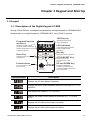
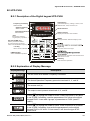
3.1.1 Description of the Digital Keypad LC-M2E
Among VFD-M-D series, messages are displayed by the digital keypad for VFD004M21B-D,
whereas there is no digital keypad for VFD004M21W-D, use of PU06 is optional.
LED Display
Program/Function
mode key
Selects normal mode/
program mode. Displays
the AC drive status, such as
output frequency.
Enter Key
DIGITAL KEYPAD
Indicates motor and
drive parameter.
LED Indicates
RUN
STOP
FWD
REV
MOD E
RUN
ENTE R
STOP
RES ET
Lamp lights during RUN,
STOP, FWD & REV
operation.
Run key
Starts AC drive operation.
Used to enter programming
parameters
Potentiometer
It is no function for this
specific drive
50
VFD-M
100
0
FREQ SET
LC-M2E
Display Message
STOP/RESET Key
Stops and resets the
parameter after a fault
occurs.
UP and DOWN Key
Sets the parameter
number or changes the
numerical data such as the
freq. reference.
Descriptions
Displays the AC drive Master Frequency.
Displays the actual output frequency present at terminals U/T1, V/T2,
and W/T3.
User defined unit (where U = F x Pr.0-05)
Displays the output current present at terminals U/T1, V/T2, and
W/T3.
Displays the AC motor drive forward run status.
Displays the AC motor drive reverse run status.
Revision May 2009, MDE5, SW V1.1
3-1
Chapter 3 Keypad and Start Up|VFD-M-D Series
Display Message
Descriptions
Displays the selected parameter.
Displays the actual stored value of the selected parameter.
External Fault.
Display “End” for approximately 1 second if input has been accepted.
Display “Err”, if the input is invalid.
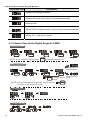
3.1.2 How to Operate the Digital Keypad LC-M2E
Selection mode
畫面選擇
START
MODE
MODE
MODE
MODE
MODE
G O STA RT
NOTE: In the selection mode, press
ENTER
to set the parameters.
To set parameters
parameter set
successfully
ENTER
or
ENTER
ENTER
MODE
move to previous
display
NOTE: In the parameter setting mode, you can press
to return to the selection mode.
parameter set
error
MODE
資料修改
To modify data
START
轉向設定
To set direction
or
3-2
or
Revision May 2009, MDE5, SW V1.1
Chapter 3 Keypad and Start Up|VFD-M-D Series
3.1.3 LC-M2E
Unit: mm [inch]
Reference Table for the 7-segment LED Display of the Digital Keypad
Digit
LED
Display
English
alphabet
0
1
2
3
4
5
6
7
8
9
A
b
Cc
d
E
F
G
Hh
I
Jj
K
L
n
Oo
P
q
r
S
Tt
U
v
Y
Z
LED
Display
English
alphabet
LED
Display
English
alphabet
LED
Display
Revision May 2009, MDE5, SW V1.1
3-3
Chapter 3 Keypad and Start Up|VFD-M-D Series
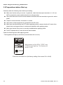
3.2 Preparations before Start-up
Carefully check the following items before proceeding.
Make sure that the wiring is correct. In particular, check that the output terminals U, V, W. are
NOT connected to power and that the drive is well grounded.
Verify that there are no short-circuits between terminals and from terminals to ground or mains
power.
Check for loose terminals, connectors or screws.
Verify that no other equipment is connected to the AC motor
Make sure that all switches are OFF before applying power to ensure that the AC motor drive
doesn’t start running and there is no abnormal operation after applying power.
Make sure that the front cover is correctly installed before applying power.
Do NOT operate the AC motor drive with humid hands.
Check the following items after applying power:
- The keypad should light up as follows (normal status with no error)
DIGITAL KEYPAD
RUN
STOP
FWD
REV
M ODE
RUN
ENTER
STO P
RESET
When power is ON, LEDs "STOP" and
"FWD" should light up. The display will
show "F4.00" .
50
VFD-M
10 0
0
FREQ SET
LC-M2E
- The built-in fan should run (the factory setting of fan control Pr.0-16=03)
3-4
Revision May 2009, MDE5, SW V1.1
Chapter 3 Keypad and Start Up|VFD-M-D Series
3.3 Operation Method
The operation method can be set via control terminals and LC-M2E keypad. Please choose a suitable
method depending on application and operation rule.
Operation Method
Operation
Command Source
Frequency Source
RUN
LC-M2E keypad
STOP
RESET
VP Voltage
+12/24V
PG A
GND B
VP
A
B
DCM
MI1
MI2
MI3
MI4
MI5
F D
REV
Force stop
Emergency stop
Door open limit signal
Operate from
external signal
24V
12V
Door close limit signal
Demo mode
FWD/STOP
REV/STOP
Digital signal common
Multi-function
input terminals
External terminals
input:
FWD-DCM
REV-DCM
DCM
*Don't apply the mains voltage
directly to above terminals
.
Parameter setting:
Pr. 5-00~Pr.5-04 to 01~04
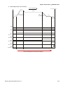
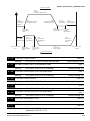
3.4 Trial Run
After finishing checking the items in “3.2 preparation before start-up”, you can perform a trial run. The
factory setting of the operation source is from the keypad (Pr.0-12=00).
1.
After applying power, verify that the display shows F4.00Hz.
2.
Pressing RUN
key for forward running (door close). And if you want to change to reverse
running (door open), you should press
stop, please press
STOP
RESET
Revision May 2009, MDE5, SW V1.1
or
key. And if you want to decelerate to
key.
3-5
Chapter 3 Keypad and Start Up|VFD-M-D Series
3.
Check following items:
Check if the motor direction of rotation is correct.
Check if the motor runs steadily without abnormal noise and vibration.
Check if acceleration and deceleration are smooth.
If the results of trial run are normal, please start the formal run.
NOTE
1.
Stop running immediately if any fault occurs and refer to the troubleshooting guide for solving
the problem.
2.
Do NOT touch output terminals U, V, W when power is still applied to L1/R, L2/S, L3/T even
when the AC motor drive has stopped. The DC-link capacitors may still be charged to
hazardous voltage levels, even if the power has been turned off.
3.
To avoid damage to components, do not touch them or the circuit boards with metal objects or
your bare hands.
3-6
Revision May 2009, MDE5, SW V1.1
Chapter 4 Parameters|VFD-M-D Series
Chapter 4 Parameters
The VFD-M-D parameters are divided into 9 groups by property for easy setting. In most applications,
the user can finish all parameter settings before start-up without the need for re-adjustment during
operation.
The 9 groups are as follows:
Group 0 User Parameters
Group 1 Basic Parameters
Group 2 Motor and Feedback Function Parameters
Group 3 Door Open Parameters
Group 4 Door Close Parameters
Group 5 Multi-Step Speed and PLC Parameters
Group 6 Digital Output Parameters
Group 7 Protection and Special Parameters
Group 8 Communication Parameters
Revision May 2009, MDE5, SW V1.1
4-1
Chapter 4 Parameters|VFD-M-D Series
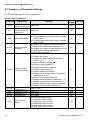
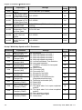
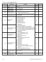
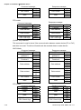
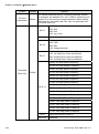
4.1 Summary of Parameter Settings
: The parameter can be set during operation.
Group 0 User Parameters
Parameter
0-00
0-01
0-02
0-03
0-04
0-05
0-06
0-07
0-08
0-09
4-2
Explanation
Factory
Customer
Setting
Settings
Identity Code of
Read-only
the AC motor drive
Rated Current
Display of the AC Read-only
motor drive
08: Keypad lock
09: All parameters are reset to factory settings
Parameter Reset
(50Hz, 230V)
10: All parameters are reset to factory settings
(60Hz, 220V)
00: Display the frequency command value (F)
01: Display the actual output frequency (H)
Start-up Display
02: Display the content of user-defined unit (U)
Selection
03: Multifunction display, see Pr.0-04
04: FWD/REV command
00: Display output current (A)
01: Display the pulses
02: Display the walking distance and step
speed (1.tt)
03: Display DC-BUS voltage ( u )
04: Display output voltage (E)
05: Output power factor angle (n)
Content of Multi
06: Display output power (P)
Function Display
07: Display actual motor speed
08: Display the estimated value of torque as it
relates to current (t)
09: Display PG numbers/10ms (G)
10: Display the temperature of heat sink (°C)
11: Display external input terminal status (I.)
12: Display external output terminal status (o.)
13: Display communication address (d.)
User-Defined
0.01 to 160.0
Coefficient K
Software Version Read-only
Password Input
00 to 9999
Password Set
00 to 9999
00: Distance control mode 1
01: Distance control mode 2
Door Control
02: Multi-step control mode 1
Mode
03: Multi-step control mode 2
04: Multi-step control mode 3
05: Multi-step control mode 4
##
#.#
00
00
00
1.00
#.##
00
00
00
Revision May 2009, MDE5, SW V1.1
Chapter 4 Parameters|VFD-M-D Series
Parameter
Explanation
0-10
PWM Carrier
Frequency
Selections
0-11
AVR Function
0-12
Source of
Operation
Command
0-13
Stop Method
0-14
Door Open/Close
Control
0-15
Position Mode
0-16
Fan Control
0-17
0-18
Settings
01~15 kHz
Factory
Customer
Setting
12
00: AVR function enable
01: AVR function disable
02: AVR function disable for decel.
00: Digital keypad
01: External terminals. Keypad STOP enabled.
02: External terminals. Keypad STOP disabled.
03: RS-485 serial communication (RJ-11).
Keypad STOP enabled.
04: RS-485 serial communication (RJ-11).
Keypad STOP disabled.
00: Ramp to stop
01: Coast to stop
00: Enable door open/close operation
01: Disable door open operation
02: Disable door close operation
00: No limit signal, detected by PG number or
current level
01: Door open limit signal only, door close limit
is detected by PG number or current level
02: Door close limit signal only, door open limit
is detected by PG number or current level
03: Door open and close limit signal
04: Detect by PG number and also accept
external door open/close limit signal
00: Always fan on
01: Drive stops 1 minute later, fan stop running
02: Run and fan on, stop and fan off
03: Preliminary temperature attained, fan start
to run (when temperature is equal or higher
than 60 oC, it runs. When it is less than 40
o
C, it stops.
Stall Current Level
0.0~200.0%
of Position Mode
00: V/F control
Control Methods
01: Vector Control
00
00
00
00
00
03
30.0
00
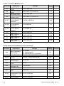
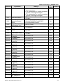
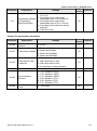
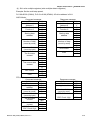
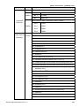
Group 1 Basic Parameters
Parameter
1-00
1-01
1-02
Explanation
Maximum Output
Frequency (Fmax)
Maximum Voltage
Frequency (Fbase)
Maximum Output
Voltage (Vmax)
Revision May 2009, MDE5, SW V1.1
Settings
Factory
Customer
Setting
50.00 to 400.0 Hz
60.00
0.10 to 400.0 Hz
60.00
230V series: 0.1V to 255.0V
220.0
4-3
Chapter 4 Parameters|VFD-M-D Series
Parameter
1-03
1-04
1-05
1-06
1-07
1-08
1-09
1-10
1-11
1-12
1-13
Explanation
Mid-Point Frequency
(Fmid)
Mid-Point Voltage
(Vmid)
Minimum Output
Frequency (Fmin)
Minimum Output
Voltage (Vmin)
Frequency Setting
for Low Speed
Operation
Acceleration Time
for Low Speed
Operation
Deceleration Time
for Low Speed
Operation
Skip Frequency 1
Upper Limit
Skip Frequency 1
Lower Limit
Skip Frequency 2
Upper Limit
Skip Frequency 2
Lower Limit
Settings
Factory
Customer
Setting
0.10 to 400.0 Hz
0.50
230V series: 0.1V to 255.0V
1.7
0.10 to 400.0 Hz
0.50
230V series: 0.1V to 255.0V
1.7
0.10 Hz to 400.0 Hz
4.00
0.1 to 3600 sec
2.0
0.1 to 3600 sec
2.0
0.00 to 400.0 Hz
0.00
0.00 to 400.0 Hz
0.00
0.00 to 400.0 Hz
0.00
0.00 to 400.0 Hz
0.00
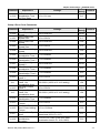
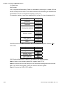
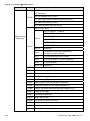
Group 2 Motor and Feedback Function Parameters
Parameter
2-00
2-01
2-02
2-03
2-04
2-05
2-06
2-07
2-08
2-09
4-4
Explanation
Settings
00: Disable
01: Auto tuning R1
02: Auto tuning R1 + no-load test
Motor Rated Current FLA*5% ~ FLA*120% (FLA=2.5A)
Motor No-Load
FLA*0% ~ motor rated current
Current
Torque
0.0 to 10.0
Compensation
Number of Motor
02~16
Poles
Motor Line-to-line
0.00~99.99 Ω
Resistance R1
Motor Rated Slip
0.00 to 20.00 Hz
Slip Compensation
0 to 250%
Limit
Torque
Compensation Time 0.01 to 10.00 Sec
Constant
Slip Compensation
0.01 to 10.00 Sec
Time Constant
Motor Parameters
Auto Tuning
Factory
Customer
Setting
00
2.50
1.00
1.0
04
0.00
3.00
200
0.05
0.10
Revision May 2009, MDE5, SW V1.1
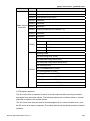
Chapter 4 Parameters|VFD-M-D Series
Parameter
2-10
2-11
2-12
Explanation
Settings
Compensation
Coefficient for Motor 00 to 16
Instability
PG Pulse Range
00 to 4000
00: Disable
01: Forward / CCW rotation (A phase leads
PG Input
B phase)
02: Forward / CCW rotation (B phase leads
A phase)
Factory
Customer
Setting
07
600
00
2-13
Electrical Gear A
01 to 5000
100
2-14
Electrical Gear B
01 to 5000
100
0.0 to 10.0
0.5
0.00 to 100.00 (0.00 disable)
1.00
2-15
2-16
2-17
2-18
2-19
2-20
2-21
2-22
2-23
2-24
2-25
2-26
2-27
2-28
ASR (Auto Speed
Regulation for door
open) control (with
PG only) (P)
ASR (Auto Speed
Regulation for door
open) control (with
PG only) (I)
PG Slip
Compensation Limit
Deviation Range of
PG Feedback Signal
Error
PG Feedback Signal
Detection Time
Treatment of the
Erroneous PG
Feedback Signals
Sample time for
refreshing the
content of 210DH
and 210EH
Door Width Autotuning Frequency
Door Width Autotuning Function
Door Width Pulses
(Unit: 1)
Door Width Pulses
(Unit: 10000)
0.00 to 60.00 Hz
20.00
0.01 to 100 Hz
3.00
0.0 to 100.0 sec
1.0
00: Warn and keep operation
01: Fault and RAMP to stop
02: Warn and low speed operation
02
0.01 to 1.00 sec
0.10
0.10 to 1.00 sec
0.10
00: disable
01: enable
00
01 to 9999
7500
00 to 99
00
0.0 to 10.0
0.5
Reserved
Reserved
ASR (Auto Speed
Regulation for door
close) control (with
PG only) (P)
Revision May 2009, MDE5, SW V1.1
4-5
Chapter 4 Parameters|VFD-M-D Series
Parameter
2-29
Explanation
ASR (Auto Speed
Regulation for Door
Close) control (with
PG only) (I)
Factory
Customer
Setting
Settings
0.00 to 100.00 (0.00 disable)
1.00
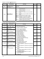
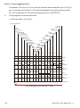
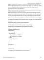
Group 3 Door Open Parameters
Parameter
3-00
3-01
3-02
3-03
3-04
3-05
3-06
3-07
3-08
3-09
3-10
3-11
3-12
3-13
3-14
3-15
3-16
3-17
4-6
Explanation
Door Open Coupling
Speed
Door Open High
Speed Start
Door Open High
Speed 1
Door Open Final
Speed Start
Door Open Final
Speed
Door Open Holding
Speed Start
Door Open Holding
Speed
Door Open
Acceleration Time 1
Door Open
Deceleration Time 1
Door Open High
Speed 2
Door Open
Acceleration Time 2
Door Open
Deceleration Time 2
Door Open Holding
Torque
Response Time of
Door Open Holding
Torque
Door Open Time-out
Setting
The Current Level 1
to Decrease to Pr.312 after Door Open
Completed
The Current Level 2
to Decrease to Pr.312 after Door Open
Completed
Holding Time for
Terminal REV
Factory
Customer
Setting
Settings
0.00 to 400.0Hz
8.40
00 to 65535 (Pluses number)
300
0.00 to 400.0Hz
42.00
0.0 to 100.0%
95.0
0.00 to 400.0Hz
5.00
0.0 to 100.0%
99.0
0.00 to 400.0Hz
2.00
0.1 to 3600sec
2.0
0.1 to 3600sec
2.0
0.00 to 400.0Hz
30.00
0.1 to 3600sec
10.0
0.1 to 3600sec
10.0
0.0 to 100.0%
30.0
0.01 to 10.00sec
0.20
0.0 to 180.0sec (0.0: disable)
0.0
0.0 to 150.0%
0.0%
0.0 to 150.0%
0.0%
0.0 to 999.9 sec (999.9 sec for always
holding)
0.0
Revision May 2009, MDE5, SW V1.1
Chapter 4 Parameters|VFD-M-D Series
Parameter
3-18
Explanation
S Curve
Acceleration Time
for Door Open
Settings
0.0 to 10.0 sec
Factory
Customer
Setting
0.0
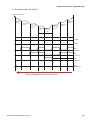
Group 4 Door Close Parameters
Parameter
4-00
4-01
4-02
4-03
4-04
4-05
4-06
4-07
4-08
4-09
4-10
4-11
4-12
4-13
4-14
4-15
4-16
4-17
4-18
Explanation
Door Close High
Speed 1
Door Close Final
Speed Start
Door Close Final
Speed
Door Close Holding
Speed Start
Door Close Holding
Speed
Door Close
Acceleration Time 1
Door Close
Deceleration Time 1
Door Close High
Speed 2
Door Close
Acceleration Time 2
Door Close
Deceleration Time 2
Re-open Current
Level 1
Re-open Current
Level 1 for
Acceleration Area
Re-open Current
Level 2
Re-open Current
Level 2 for
Acceleration Area
Re-open
Deceleration Time
Door Close Holding
Torque
Response Time of
Door Close Holding
Torque
Re-open Low Speed
Area
Re-open
Acceleration
Boundary
Revision May 2009, MDE5, SW V1.1
Settings
0.00 to 400.0Hz
Factory
Customer
Setting
30.00
0.0 to 100.0%
4.0
0.00 to 400.0Hz
5.00
0.0 to 100.0%
1.0
0.00 to 400.0Hz
2.00
0.1 to 3600sec
2.0
0.1 to 3600sec
2.0
0.00 to 400.0Hz
20.00
0.1 to 3600sec
10.0
0.1 to 3600sec
10.0
0.0 to 150.0%
100.0
100~200% (100% is Pr.4-10 setting)
0.0 to 150.0%
150
100.0
100~200% (100% is Pr.4-12 setting)
150
0.1 to 3600sec
0.2
0.0 to 100.0%
30.0
0.01 to 10.00sec
0.20
1.0 to 99.0% (100% is the door width, low
speed area is 0%~Pr. 4-17)
2.0
8.0 to 97.0% (100% is the door width,
acceleration area is Pr. 4-18~100%)
70.0
4-7
Chapter 4 Parameters|VFD-M-D Series
Parameter
4-19
4-20
4-21
4-22
4-23
4-24
4-25
Explanation
Door Close Time-out
Setting
The Current Level 1
to Decrease to Pr.415 after Door Close
The Current Level 2
to Decrease to Pr.415 after Door Close
Holding Time for
Terminal FWD
S Curve
Acceleration Time
for Door Close
Re-open Current
Level 1 for Low
Speed
Re-open Current
Level 2 for Low
Speed
Factory
Customer
Setting
Settings
0.0 to 180.0sec (0.0: disable)
0.0
0.0~150.0%
0.0
0.0~150.0%
0.0
0.0 to 999.9 sec (999.9 sec for always
holding)
0.0
0.0 to 10.0 sec
0.0
0.0~150.0%
100.0
0.0~150.0%
100.0
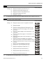
Group 5 Multi-Step Speed and PLC Parameters
Parameter
5-00
Multi-Function Input
Terminal (MI1)
5-01
Multi-Function Input
Terminal (MI2)
5-02
5-03
5-04
5-05
5-06
5-07
Multi-Function Input
Terminal (MI3)
Multi-Function Input
Terminal (MI4)
Multi-Function Input
Terminal (MI5)
Multi-Function Input
Terminal (A)
Multi-Function Input
Terminal (B)
Multi-Function Input
Terminal (COM1)
5-08
Multi-Function Input
Terminal (COM2)
5-09
Multi-Function Input
Terminal (COM3)
5-10
4-8
Explanation
Multi-Function Input
Terminal (COM4)
Factory
Customer
Setting
Settings
00: No function
01: Multi-step speed command 1
02: Multi-step speed command 2
03: Multi-step speed command 3
04: Multi-step speed command 4
05: 1st/2nd Accel/decel Time Selection
06: Low speed operation
07: FWD/REV command for low speed
operation
08: Demo mode
09: Force stop (NO)
10: Force stop (NC)
11: Emergency stop (NO)
12: Emergency stop (NC)
13: Operation command selection
(Keypad/external terminal)
14: Parameter lock enable (NC)
15: Reset (NO)
16: Reset (NC)
17: The signal when it is in open completed
position
18: The signal when it is in close completed
position
19: Open allowance signal
20: Force door open signal
21: Home return
00
00
00
00
00
00
00
00
00
00
00
Revision May 2009, MDE5, SW V1.1
Chapter 4 Parameters|VFD-M-D Series
Parameter
Explanation
Settings
Factory
Customer
Setting
22: The curve selection for 1st/2nd step
door open/close
23: The signal when it is in open completed
position, including RUN signal
5-11
5-12
5-13
5-14
5-15
5-16
5-17
5-18
5-19
5-20
5-21
5-22
5-23
5-24
5-25
5-26
5-27
5-28
5-29
5-30
5-31
5-32
Line Start Lockout
24: The signal when it is in close completed
position, including RUN signal
00: Disable
01: Enable
00: 2-wire (FWD/STOP, REV/STOP)
01: 2-wire (FWD/REV, RUN/STOP)
02: 3-wire operation control
2-wire/3-wire
Operation Control
Mode
Digital Terminal Input
01 to 20 (*2.5ms)
Debouncing Time
Waiting Time for Next
0.1 to 999.9sec
Demo
The Record for Demo
00 to 9999
Times
00: Disable
Clear Demo Times
01: Enable
1st Step Speed
0.00 to 400.0 Hz
Frequency
2nd Step Speed
0.00 to 400.0 Hz
Frequency
3rd Step Speed
0.00 to 400.0 Hz
Frequency
4th Step Speed
0.00 to 400.0 Hz
Frequency
5th Step Speed
0.00 to 400.0 Hz
Frequency
6th Step Speed
0.00 to 400.0 Hz
Frequency
7th Step Speed
0.00 to 400.0 Hz
Frequency
th
8 Step Speed
0.00 to 400.0 Hz
Frequency
9th Step Speed
0.00 to 400.0 Hz
Frequency
10th Step Speed
0.00 to 400.0 Hz
Frequency
11th Step Speed
0.00 to 400.0 Hz
Frequency
12th Step Speed
0.00 to 400.0 Hz
Frequency
13th Step Speed
0.00 to 400.0 Hz
Frequency
14th Step Speed
0.00 to 400.0 Hz
Frequency
15th Step Speed
0.00 to 400.0 Hz
Frequency
16th Step Speed
0.00 to 400.0 Hz
Frequency
Revision May 2009, MDE5, SW V1.1
00
00
01
2.0
00
00
0.00
0.00
0.00
0.00
0.00
0.00
0.00
0.00
0.00
0.00
0.00
0.00
0.00
0.00
0.00
0.00
4-9
Chapter 4 Parameters|VFD-M-D Series
Parameter
5-33
5-34
Explanation
Factory
Customer
Setting
Settings
Multi-function Input
Terminal Status
(N.O/N.C)
0~8191
0
Reset after reopen/re-close
Bit0=0: Disable to detect the incorrect
open/close limit
Bit0=1: Enable to detect the incorrect
open/close limit
Bit1=0: Enable to re-open when door close
error
Bit1=1: Disable to re-open when door close
error
Bit2=0: Enable S-Curve when re-open
Bit2=1: Disable S-Curve when re-open
Bit3=0: Disable to reset door width to
100.0% after door open completed
Bit3=1: Enable to reset door width to
100.0% after door open completed
00
Group 6 Digital Output Parameters
Parameter
6-00
6-01
6-02
6-03
6-04
6-05
4-10
Factory
Customer
Setting
Explanation
Settings
Multi-function Output
(RA1, RB1, RC1)
Multi-function Output
(RA2, RC2)
Multi-function Output
MO1
(communication)
Multi-function Output
MO2
(communication)
Multi-function Output
MO3
(communication)
Multi-function Output
MO4
(communication)
00: No function
01: AC drive operational
02: Master frequency attained
03: Over-Torque Detection
04: Low-Voltage Indication
05: Operation Mode Indication
06: Fault Indication
07: Warning Indication
08: Demo Indication
09: A Step Completed
10: A Demo Completed
11: Forced Stop Indication
12: Heat Sink Overheat Warning
13: AC Drive Ready
14: Emergency Stop
15: Soft Brake Signal
16: Zero Speed Output Signal
17: Feedback Signal Error
18: Position Detection 1 (both door open and
close)
19: Position Detection 2 (both door open and
close)
20: Position Detection 3 (both door open and
close)
21: The signal outputs when it is in close
completed position
22: The signal outputs when it is in open
completed position
23: Door Close Error
24: Reserved
6-06
Multi-function Output
MO5
(communication)
6-07
Multi-function Output
MO6
(communication)
00
00
00
00
00
00
00
00
Revision May 2009, MDE5, SW V1.1
Chapter 4 Parameters|VFD-M-D Series
Parameter
Explanation
Settings
Factory
Customer
Setting
25: Position Complete Signal
26: Reserved
27: Position Detection 1 (door close only)
28: Position Detection 2 (door close only)
29: Position Detection 3 (door close only)
30: Position Detection 1 (door open only)
31: Position Detection 2 (door open only)
32: Position Detection 3 (door open only)
6-08
6-09
6-10
6-11
6-12
~
6-15
Multi-function Output
status
Position Detection 1
Position Detection 2
Position Detection 3
00 to 255
00
0.0 to 100.0%
0.0 to 100.0%
0.0 to 100.0%
25.0
12.5
7.5
Reserved
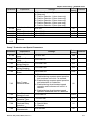
Group 7 Protection and Special Parameters
Parameter
7-00
7-01
7-02
7-03
7-04
7-05
7-06
7-07
7-08
7-09
Explanation
Software Brake
Level
DC Brake Current
Level
DC Brake Time
during Start-Up
DC Brake Time
during Stopping
Start-Point for DC
Brake
Over-Torque
Detection Mode
Over-Torque
Detection Level
Over-Torque
Detection Time
Electronic Thermal
Overload Relay
Selection
Electronic Thermal
Characteristic
Revision May 2009, MDE5, SW V1.1
Settings
Factory
Customer
Setting
370~430 Vdc
380
0.0 to 100.0 %
0.0
0.0 to 999.9 sec
0.0
0.0 to 999.9 sec
0.0
0.00 to 400.0Hz
0.00
00: Disabled
01: Enabled during constant speed operation
and continues until oL/oL1 is reached.
02: Enabled during constant speed operation
and halted after oL2 detection
03: Enabled during Accel/constant speed
operation and continues until oL/oL1 is
reached
04: Enabled during Accel/constant speed
operation and halted after oL2 detection
00
10.0 to 200.0%
150.0
0.1 to 60.0 sec
0.1
00: Standard Motor
01: Special Motor
02: Disabled
01
30 to 600 sec
60
4-11
Chapter 4 Parameters|VFD-M-D Series
Parameter
7-10
7-11
7-12
Explanation
Auto Restart After
Fault
Delay Time for
Speed Search
Current Limit for
Speed Search
Factory
Customer
Setting
Settings
00 to 10
06
0.1 to 600.0 sec
2.0
20.0 to 200.0%
150.0
7-13
Speed Trace at
Restart after Fault
00: Speed search starts with the Master
Frequency reference value
01: Starts with the minimum output frequency
7-14
Auto Reset Time at
Restart after Fault
00 to 9999sec
7-15
7-16
7-17
7-18
7-19
7-20
4-12
00: No fault
01: Over Current (oc)
02: Over Voltage (ov)
03: Overheat (oH)
Present Fault
Record
04: Overload (oL)
05: Overload (oL1)
06: External Fault (EF)
07: Reserved
08: CPU failure (cF3)
09: Hardware Protection Failure (HPF)
10: Current exceed during Acceleration (ocA)
Second Most Recent
11: Current exceed during Deceleration (ocd)
Fault Record
12: Current exceed during Steady State (ocn)
13: Ground Fault (GFF)
14: Reserved
15: CPU READ failure (CF1)
16: CPU WRITE failure (CF2)
Third Most Recent
17: Reserved
Fault Record
18: Motor overload (oL2)
19: Reserved
20: Software/password protection
(PcdE/Ccde)
21: Reserved
22: Reserved
23: Reserved
Fourth Most Recent 24: Reserved
Fault Record
25: Reserved
26: PG feedback error (PGEr)
27: Door open/close complete signal error
(PSEr)
28: Door open time-out (ٛ eca)
35: Communication time-out (CE10)
Accumulative Motor
00 to 1439 min
Operation Time
(Min.)
Accumulative Motor
00 to 9999 day
Operation Day
01
600
00
00
00
00
00
00
Revision May 2009, MDE5, SW V1.1
Chapter 4 Parameters|VFD-M-D Series
Parameter
7-21
Explanation
Settings
00: According to the fast deceleration time
(Pr.4-14)
01: According to door open/close
Deceleration Method
deceleration time 1 (Pr.3-08/4-06)
for Emergency
02: According to door open/close
Stop/Forced Stop
deceleration time 2 (Pr.3-11/4-09)
03: According to DC brake time during
stopping
04: Free run to stop
Factory
Customer
Setting
00
Group 8 Communication Parameters
Parameter
8-00
8-01
8-02
Explanation
Communication
Address
Settings
01 to 254
00: Baud rate 4800bps
01: Baud rate 9600bps
Transmission Speed
02: Baud rate 19200bps
03: Baud rate 38400bps
00: Warn and keep operating
01: Warn and ramp to stop
Transmission Fault
Treatment
02: Warn and coast to stop
Factory
Customer
Setting
01
02
03
03: No warning and keep operating
8-03
Time-out Detection
8-04
Communication
Protocol
8-05
Response Delay
Time
Revision May 2009, MDE5, SW V1.1
0.0 ~ 60.0 seconds (0.0: Disable)
00: 7,N,2 (Modbus, ASCII)
01: 7,E,1 (Modbus, ASCII)
02: 7,O,1 (Modbus, ASCII)
03: 8,N,2 (Modbus, RTU)
04: 8,E,1 (Modbus, RTU)
05: 8,O,1 (Modbus, RTU)
0.0
00 ~ 200 msec
00
03
4-13
Chapter 4 Parameters|VFD-M-D Series
4.2 Description of Parameter Settings
Group 0: User Parameters
operation.
: The parameter can be set during
: This parameter can be set during operation.
0 – 00
Identity Code of the AC Motor Drive
0 – 01
Rated Current Display of the AC Motor Drive
Settings
Settings
Read Only
Factory setting: ##
Read Only
Factory setting: #.#
Pr. 0-00 displays the identity code of the AC motor drive. The capacity, rated current, rated
voltage and the max. carrier frequency relate to the identity code. Users can use the following
table to check how the rated current, rated voltage and max. carrier frequency of the AC motor
drive correspond to the identity code.
Pr.0-01 displays the rated current of the AC motor drive. By reading this parameter the user
can check if the AC motor drive is correct.
230V Series
kW
HP
Pr.0-00
Rated Output
Current (A)
Max. Carrier
Frequency
0.4
0.5
00
2.5
15KHz
0 – 02 Parameter Reset
Factory Setting: 00
Settings 08
Keypad Lock
09
All parameters are reset to factory settings (50Hz, 230V)
10
All parameters are reset to factory settings (60Hz, 220V)
This parameter allows the user to reset all parameters to the factory settings except the fault
records (Pr.7-15 ~ Pr.7-18).
50Hz: Pr.1-01 is set to 50Hz and Pr.1-02 is set to 230V.
60Hz: Pr.1-01 is set to 60Hz and Pr.1-02 is set to 230V.
4-14
When Pr.0-02=08, the keypad is locked. To unlock the keypad, set Pr.0-02=00.
Revision May 2009, MDE5, SW V1.1
Chapter 4 Parameters|VFD-M-D Series
0 – 03
Start-up Display Selection
Factory Setting: 00
Settings 00
Display the frequency command value. (F)
01
Display the actual output frequency (H)
02
Display the content of user-defined unit (U)
03
Multifunction display, see Pr.0-04
04
FWD/REV command
This parameter determines the start-up display page after power is applied to the drive.
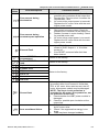
0 – 04
Content of Multi-Function Display
Factory Setting: 00
Settings 00
Display the output current in A supplied to the motor
01
Display the pulses
02
Display the walking distance and step speed (x.yy.y)
03
Display the actual DC BUS voltage in VDC of the AC
motor drive
04
Display the output voltage in VAC of terminals U, V, W
to the motor.
05
Display the power factor angle in º of terminals U, V, W
to the motor.
06
Display the output power in kW of terminals U, V and W
to the motor.
07
Display the actual motor speed in rpm (enabled in
vector control mode or PG (Encoder) feedback control)
08
Display the estimated value of torque in Nm as it relates
to current.
09
Display PG encoder feedback pulses/10ms.
Display value= (rpm*PPR)/6000 (see note)
10
Display the temperature of heat sink in °C.
11
Display external input terminal status (I.)
12
Display external output terminal status (o.)
13
Display communication address (d.)
This parameter sets the display when Pr. 0-03 is set to 03.
Revision May 2009, MDE5, SW V1.1
4-15
Chapter 4 Parameters|VFD-M-D Series
[( rpm XPPR)/1000]X10=Pulse/10ms
60
Setting 09: the display value is
with rpm=motor speed in revs/min; PPR=encoder pulse per revolution; 1000 (1 sec=1000ms);
10: encoder pulse per 10ms.
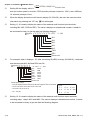
When the display shows the multi-function display (Pr.0-03=03), the user also can view other
on the keypad.
information by pressing the “UP” key
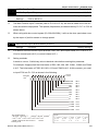
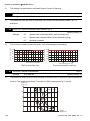
Setting 11: It is used to display the status of the external multi-function input terminals,
including MI1~MI5, FWD and REV. The value it displays is hexadecimal number. It needs to
be converted to binary to get the result as following diagram.
Weights 2 7 2 6 2 5 2 4 2 3 2 2 2 1 2 0 *0=OFF *1=ON
Bit
7 6 5 4 3 2 1 0
MI1
MI2
MI3
MI4
MI5
FWD
REV
Reserved
For example: when it displays I. 52. After converting 52(HEX) to binary (01010010), it indicates
that the terminals MI2, MI5 and REV are ON.
7
6
5
4
3
2
1
0
Weights 2 2 2 2 2 2 2 2
Bit
0 1 0 1 0 0 1 0
*0=OFF *1=ON
MI1
=OFF
MI2
=ON
MI3
=OFF
MI4
=OFF
MI5
=ON
FWD =OFF
REV =ON
Reserved
The display value
7
6
5
4
2
3
1
0
=bit7x2+bit6x2+bit5x2+bit4x2+bit3x2+bit2x2+bit1x2+bit0x2
7
6
5
4
3
2
1
0
=0x2+1x2+0x2+1x2+0x2+0x2+1x2+0x2
NOTE:
2=8
2=16
2
2=32
2=2
=82 =52 (H)
0
1
2=1
=0+64+0+16+0+0+2+0
2=4
3
2=64
4
2=128
6
7
5
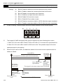
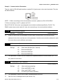
Setting 12: It is used to display the status of the external multi-function output terminals,
including relay1, relay2, MO1 and MO2. The value it displays is hexadecimal number. It needs
to be converted to binary to get the result as following diagram.
4-16
Revision May 2009, MDE5, SW V1.1
Chapter 4 Parameters|VFD-M-D Series
Weights 2 3 2 2 2 1 2 0 *0=OFF *1=ON
Bit
3 2 1 0
Relay 1
Relay 2
MO1
MO2
For example: when it displays o. C. After converting C(HEX) to binary (1100), it indicates that
the terminals MO1 and MO2 are ON.
3
2
1
0
Weights 2 2 2 2
Bit
1 1 0 0
*0=OFF *1=ON
Relay 1 =OFF
Relay 2 =OFF
MO1
MO2
The display value
3
2
1
0
=bit3x2+bit2x2+bit1x2+bit0x2
2
1
=1x2+1x2+0x2+0x2
0
=8+4+0+0
=12 =C (H)
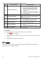
0 – 05
NOTE:
0
2=1
1
2=2
2
2=4
3
2=64
4
2=128
2=8
2=16
6
7
5
2=32
User Defined Coefficient K
Settings
=ON
=ON
0.1 to 160.0
Unit: 0. 1
Factory Setting: 1.0
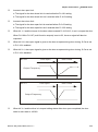
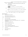
The coefficient K determines the multiplying factor for the user-defined unit.
The display value is calculated as follows:
U (User-defined unit) = Frequency Command * K (Pr.0-05)
H (actual output) = Actual output frequency * K (Pr.0-05)
Example:
A conveyor belt runs at 13.6m/s at motor speed 60Hz.
K = 13.6/60 = 0.21 (0.226667 rounded to 1 decimal), therefore Pr. 0-05=0.2
With Frequency command 35Hz, display shows U and 35*0.2=7.0m/s.
(To increase accuracy, use K=2.2 or K=22.7 and disregard decimal point.)
0 – 06
Software Version
Settings
Read Only
Display
#.#
Revision May 2009, MDE5, SW V1.1
4-17
Chapter 4 Parameters|VFD-M-D Series
0 – 07
Unit: 1
Password Input
Settings
00 to 9999
Display
00~02 (times of wrong password)
Factory Setting: 00
The function of this parameter is to input the password that is set in Pr.0-08. Input the correct
password here to enable changing parameters. You are limited to a maximum of 3 attempts.
After 3 consecutive failed attempts, a blinking “PcdE” will show up to force the user to restart
the AC motor drive in order to try again to input the correct password.
Password Set
0 – 08
Unit: 1
Settings
00 to 9999
Display
00
No password set or successful input in Pr. 0-07
Factory Setting: 00
01
Password has been set
To set a password to protect your parameter settings.
If the display shows 00, no password is set or password has been correctly entered in Pr.0-07.
All parameters can then be changed, including Pr.0-08.
The first time you can set a password directly. After successful setting of password the display
will show 01.
Be sure to record the password for later use.
To cancel the parameter lock, set the parameter to 00 after inputting correct password into Pr.
0-07.
The password consists of min. 1 digit and max. 4 digits.
How to make the password valid again after decoding by Pr.0-07:
Method 1: Re-input original password into Pr.0-08 (Or you can enter a new password if you
want to use a changed or new one).
Method 2: After rebooting, password function will be recovered.
4-18
Revision May 2009, MDE5, SW V1.1
Chapter 4 Parameters|VFD-M-D Series
Password Decode Flow Chart
0-08
0-07
Displays 00 when
entering correct
password into
Pr.0-07.
Correct Password
END
Incorrect Password
END
0-08
0-07
Displays 00 when
entering correct
password into
Pr.0-07.
3 chances to enter the correct
password.
1st time displays "01" if
password is incorrect.
2nd time displays "02", if
password is incorrect.
3rd time displays "Pcde"
(blinking)
If the password was entered
incorrectly after three tries,
the keypad will be locked.
Turn the power OFF/ON to
re-enter the password.
0 – 09 Door Control Mode
Factory Setting: 00
Settings
00
Distance control mode 1
01
Distance control mode 2
02
Multi-step control mode 1
03
Multi-step control mode 2
04
Multi-step control mode 3
05
Multi-step control mode 4
This parameter is used to select the control mode of AC motor drives. Refer to the following
explanation for detail.
00 Distance control mode 1
The drive is controlled by sensorless control. It should be set the Pr.2-11~Pr.2-14 correctly. It
will store the door width in Pr.2-24 and Pr.2-25 by Auto-tuning. It operates the door for speed
switch and completed position by counting the PG pulses. In this mode, position function will
be executed whenever power again and operates with low speed to the 0% or 100% door
width by the operation direction.
Revision May 2009, MDE5, SW V1.1
4-19
Chapter 4 Parameters|VFD-M-D Series
O pen Do or ( REV)
3- 02
1s t Step
Do or O pen H igh Sp eed
3- 00
Do or Op en
Co up ling
Sp eed
3- 07
1st S tep Do or Open
Ac ce leration Time
3-08
1s t Step Do or Ope n
Dece lera tio n Time
3- 03
Do or Op en F ina l
Sp ee d Start
3- 01
Do or Open
High Spe ed
St art
4- 04
4- 02
Do or Clo se
Door Clo se
Ho lding Spe ed Final Speed
Door Clo se Limit
0.0%
4- 03
Do or Clo se
Ho ldi ng Spe ed
St art
3 -04
Do or Op en
Final Speed
3- 05
Door Open
Holding
Sp ee d S tart
4- 05
Do or Clo se
Ac ce leration
Time 1
4- 06
Do or Clo se
De ce lera tio n
Time 1
4- 01
Do or Close
Fi nal Spe ed
Start
3- 06
Do or Op en
Ho lding Spe ed
4- 00
Do or Clo se
Hi gh Spe ed 1
Do or Op en L imit
100 .0%
Cl ose Do or (FW D)
01 Distance control mode 2
This function is the same as “00 distance control mode 1”. The difference is using PG to
control the speed. Refer to the following diagram for detail. In this mode, position function will
be executed whenever power again and operates with low speed to the 0% or 100% door
width by the operation direction.
02 Multi-step control mode 1
The drive is controlled by sensorless control. For operating the door, it uses four multi-input
(level trigger) for speed switch and limit switches for completed position.
4-20
Revision May 2009, MDE5, SW V1.1
Chapter 4 Parameters|VFD-M-D Series
5-25
9th step
5-24
8th step
5-23
7th step
Frequency
5-26
10th step
5-27
11th step
5-28
12th step
5-22
6th step
5-21
5th step
5-20
4thstep
5-19
3rd step
5-18
2nd step
5-29
13th step
5-30
14th step
5-31
15th step
5-32
16th step
5-17
1st step
1
2
3
4
5
6
7
8
9
10
11
12 13 14 15
16
03 Multi-step control mode 2
The drive is controlled by sensorless control. For operating the door, it uses three multi-input
(level trigger) and operation direction (FWD/REV) to deal with speed switch and limit switch to
deal with completed position. (4th logic signal: open: 0, close: 1)
Open Door (REV)
5-17
1st step
speed
5-25
9th step
speed
5-18
2nd step
speed
5-26
10th step
speed
Door Close Limit
0.0%
Revision May 2009, MDE5, SW V1.1
5-19
3rd step
speed
5-20
4th step
speed
5-27
11th step
5-28
speed
12th step
speed
5-21
5th step
speed
5-29
13th step
speed
Close Door (FWD)
5-22
6th step
speed
5-30
14th step
speed
5-23
7th step
speed
5-31
15th step
speed
5-24
8th step
speed
5-32
16th step
speed
Door Open Limit
100.0%
4-21
Chapter 4 Parameters|VFD-M-D Series
04 Multi-step control mode 3
The drive is controlled by sensorless control. For operating the door, it switches speed by
external signal and uses limit switch to deal with completed position. The signals must be edge
trigger. In this mode, it needs to run the door to the close complete position after power on
again or AC motor drive stops.
Open Door (REV)
5-19
5-20
3- 07
1s t S tep Do or Ope n
Ac ce lera tio n Time
5-18
3- 08
1s t Step Do or O pen
Decelera tio n Time
5-21
5-22
5-23
5-24
4- 05
Door Close
Acceleration
Time 1
4- 06
Do or Clo se
De ce lera tion
Time 1
5-27
5-26
5-25
Door Close Limit
0.0%
MI1
MI2
MI3
MI4
Door Open Limit
100.0%
Close Door (FWD)
05 Multi-step control mode 4
The speed curve is the same as multi-speed step mode 3, but the speed switch signals are
level trigger. In this mode, it can switch speed without detecting speed switch limit to run to the
door close complete position after power on again.
Comparison Table
Advantage
00 Distance
control mode 1
Uses PG signal to distinguish the
position for speed switch without
sensor.
Disadvantage
It depends on PG signal highly. It will
cause pulse loss or wrong position for
speed switch when getting error PG
signal.
01 Distance
control mode 2
Uses PG signal to distinguish the
position for speed switch without
sensor and control output frequency
precisely.
02 Multi-step
control mode 1
Uses four multi-input signal for
It needs to have sensor and external
switching 16-step speed. That means it controller to distinguish operation
has 16-step speed for single direction. direction.
4-22
It will cause incorrect output frequency
due to inaccurate PG feedback signal
or low PG resolution.
Revision May 2009, MDE5, SW V1.1
Chapter 4 Parameters|VFD-M-D Series
Advantage
Disadvantage
03 Multi-step
control mode 2
Uses three multi-input signal and
operation direction for switching 16step speed, It doesn’t need external
controller to distinguish operation
direction.
04 Multi-step
control mode 3
There is only 5-step speed for the
Uses edge trigger for speed switch. It
single direction. It needs to run to the
has 5-step speed for the single
close complete position after power on
direction to simplify the detection of the
again or AC motor drive stops due to
position sensor.
the edge trigger.
05 Multi-step
control mode 4
Uses level trigger for speed switch. It
There is only 5-step speed for the
has 5-step speed for the single
direction to simplify the detection of the single direction.
position sensor.
0 – 10
Unit: 1
PWM Carrier Frequency Selection
Settings
230V Series
It needs to have sensor. To compare
with “02 multi-step control mode 1”, it
only has 8-step speed for the single
direction.
01 to 15kHz
Factory Setting: 12
Power
Setting Range
Factory Setting
0.5HP (0.4kW)
01~15kHz
12kHz
This parameter determines the PWM carrier frequency of the AC motor drive.
Carrier
Frequency
Acoustic
Noise
1kHz
Significant
Electromagnetic
Noise or leakage
current
Minimal
Heat
Dissipation
Current
Wave
Minimal
Minimal
Significant
Significant
8kHz
15kHz
Minimal
Significant
From the table, we see that the PWM carrier frequency has a significant influence on the
electromagnetic noise, AC motor drive heat dissipation, and motor acoustic noise.
0 – 11
Automatic Voltage Regulation (AVR)
Factory Setting: 00
Settings
00
AVR function enabled
01
AVR function disabled
02
AVR function disabled for deceleration
Revision May 2009, MDE5, SW V1.1
4-23
Chapter 4 Parameters|VFD-M-D Series
The rated voltage of the motor is usually AC220V/200V 60Hz/50Hz and the input voltage of
the AC motor drive may vary between 180V to 264 VAC 50Hz/60Hz. Therefore, when the AC
motor drive is used without AVR function, the output voltage will be the same as the input
voltage. When the motor runs at voltages exceeding the rated voltage with 12% - 20%, its
lifetime will be shorter and it can be damaged due to higher temperature, failing insulation and
unstable torque output.
AVR function automatically regulates the AC motor drive output voltage to the Maximum
Output Voltage (Pr.1-02). For instance, if Pr.1-02 is set at 200 VAC and the input voltage is at
200V to 264VAC, then the Maximum Output Voltage will automatically be reduced to a
maximum of 200 VAC.
When motor stops with deceleration, it will shorten deceleration time. When setting this
parameter to 02 with auto acceleration/deceleration, it will offer a quicker deceleration.
0 – 12
Source of the Operation Command
Factory Setting: 00
Settings
00
Digital keypad
01
External terminals. Keypad STOP enabled.
02
External terminals. Keypad STOP disabled.
03
RS-485 serial communication (RJ-11). Keypad STOP enabled.
04
RS-485 serial communication (RJ-11). Keypad STOP disabled.
This parameter is used to set the source of the operation command.
0 – 13
Stop Method
Factory Setting: 00
Settings
00
Ramp to stop
01
Coast to stop
The parameter determines how the motor is stopped when the AC motor drive receives a valid
stop command or detects External Fault.
1. Ramp:
the AC motor drive decelerates to Minimum Output Frequency (Pr.1-05)
according to the deceleration time and then stops.
2. Coast:
the AC motor drive stops the output instantly upon command, and the motor
free runs until it comes to a complete standstill.
3. The motor stop method is usually determined by the characteristics of the motor load and
how frequently it is stopped.
4-24
Revision May 2009, MDE5, SW V1.1
Chapter 4 Parameters|VFD-M-D Series
(1)
It is recommended to use “ramp to stop” for safety of personnel or to prevent
material from being wasted in applications where the motor has to stop after the
drive is stopped. The deceleration time has to be set accordingly.
(2)
If the motor free running is allowed or the load inertia is large, it is
recommended to select “coast to stop”.
Frequency
output
frequency
Frequency
output
frequency
motor
speed
motor
speed
Time
operation
command
RUN
stops according to
decel eration time
STOP
operation
command
Time
free run to stop
RUN
STOP
ramp to stop and free run to stop
0 – 14 Door Open/Close Control
Factory Setting: 00
Settings
00
Enable door open/close operation
01
Disable door open operation
02
Disable door close operation
0 – 15 Position Mode
Factory Setting: 00
Settings
00
No limit signal, detected by PG number or current level
01
Door open limit signal only, door close limit is detected by PG number
or current level
02
Door close limit signal only, door open limit is detected by PG number
or current level
03
Door open and close limit signal
04
Detect by PG number and also accept external door open/close limit
signal
When this parameter is NOT set to 00 “No limit signal” and Pr. 0-17 is NOT set to 0, it will be
regarded as open/close complete position with following two conditions.
A. It has open/close limit signal.
B. When the current exceeds this level due to motor stall.
Revision May 2009, MDE5, SW V1.1
4-25
Chapter 4 Parameters|VFD-M-D Series
When this parameter is set to 00 “No limit signal”, the methods for detecting open/close
complete position are as follows.
A. When Pr. 0-17 is set to 0: When PG feedback frequency is almost 0 due to motor stall, it is
regarded as open/close complete position.
B. When Pr. 0-17 is NOT set to 0: When current exceeds this level due to motor stall, it is
regarded as open/close complete position.
NOTE
It is recommended to use method B for the transmission mechanism skids easily.
This function is only for the distance control mode. For multi-step control mode, please use the multiinput terminals (set one of Pr.5-00~Pr.5-10 to 17, 18, 23 or 24).
0 – 17
Settings
Unit: 0.1
Stall Current Level of Position Mode
0.0 to 200.0%
Factory Setting: 30.0
This parameter is used for the stall current level for open/close complete position and used
with Pr.0-15.
0 – 16
Fan Control
Factory Setting: 03
Settings
00
Fan always ON
01
1 minute after AC motor drive stops, fan will be OFF
02
AC motor drive runs and fan ON, AC motor drive stops and fan
OFF
03
Fan ON to run when preliminary heatsink temperature attained
This parameter determines the operation mode of cooling fan.
0 – 18 Control Method
Factory Setting: 00
Settings
4-26
00
V/F control
01
Vector Control
This parameter determines the control method of the AC motor drive.
Revision May 2009, MDE5, SW V1.1
Chapter 4 Parameters|VFD-M-D Series
Group 1: Basic Parameters
1 – 00
Settings
50.00 to 400.0 Hz
Factory Setting: 60.00
This parameter determines the AC motor drive’s Maximum Output Frequency.
1 – 01
Maximum Voltage Frequency (Fbase)
Settings
Unit: 0.01
Maximum Output Frequency (Fmax)
0.10 to 400.0Hz
Unit: 0.01
Factory Setting: 60.00
This value should be set according to the rated frequency of the motor as indicated on the
motor nameplate. Maximum Voltage Frequency determines the v/f curve ratio. This parameter
value must be equal to or greater than the Mid-Point Frequency (Pr.1-03).
1 – 02
Maximum Output Voltage (Vmax)
Unit: 0.1
Settings 230V series 0.1 to 255.0V
Factory Setting: 220.0
This parameter determines the Maximum Output Voltage of the AC motor drive. The Maximum
Output Voltage setting must be smaller than or equal to the rated voltage of the motor as
indicated on the motor nameplate. This parameter value must be equal to or greater than the
Mid-Point Voltage (Pr.1-04).
1 – 03
Mid-Point Frequency (Fmid)
Settings
Unit: 0.01
0.10 to 400.0Hz
Factory Setting: 0.50
This parameter sets the Mid-Point Frequency of the V/f curve. With this setting, the V/f ratio
between Minimum Frequency and Mid-Point frequency can be determined. This parameter
must be equal to or greater than Minimum Output Frequency (Pr.1-05) and equal to or less
than Maximum Voltage Frequency (Pr.1-01).
1 – 04
Mid-Point Voltage (Vmid)
Settings
230V series
Unit: 0.1
0.1 to 255.0V
Factory Setting: 1.7
This parameter sets the Mid-Point Voltage of any V/f curve. With this setting, the V/f ratio
between Minimum Frequency and Mid-Point Frequency can be determined. This parameter
must be equal to or greater than Minimum Output Voltage (Pr.1-06) and equal to or less than
Maximum Output Voltage (Pr.1-02).
Revision May 2009, MDE5, SW V1.1
4-27
Chapter 4 Parameters|VFD-M-D Series
1 – 05
Minimum Output Frequency (Fmin)
Settings
Unit: 0.01
0.10 to 400.0Hz
Factory Setting: 0.50
This parameter sets the Minimum Output Frequency of the AC motor drive. This parameter
must be equal to or less than Mid-Point Frequency (Pr.1-03).
The settings of 1-03, 1-04, and 1-06 are invalid in Vector Control mode.
1 – 06
Minimum Output Voltage (Vmin)
Settings
230V series
Unit: 0.1
0.1 to 255.0V
Factory Setting: 1.7
This parameter sets the Minimum Output Voltage of the AC motor drive. This parameter must
be equal to or less than Mid-Point Voltage (Pr.1-04).
The settings of Pr.1-01 to Pr.1-06 have to meet the condition of Pr.1-02 ≥ Pr.1-04 ≥ Pr.1-06
and Pr.1-01 ≥ Pr.1-03 ≥ Pr.1-05.
1 – 07
Frequency Setting for Low Speed Operation
Settings
1 – 08
Factory Setting: 4.00
Unit: 0.1
0.1 to 3600 sec
Factory Setting: 2.0
Deceleration Time for Low Speed Operation
Settings
0.10 Hz to 400.0 Hz
Acceleration Time for Low Speed Operation
Settings
1 – 09
Unit: 0.1
Unit: 0.1
0.1 to 3600 sec
Factory Setting: 2.0
When using low speed function, external terminals MI1~MI5 should be set to 8. When the low
speed command is “ON”, the AC motor drive will accelerate from Minimum Output Frequency
(Pr.1-05) to Low Speed Frequency (Pr.1-07). When the low speed command is “OFF”, the AC
motor drive will decelerate from low speed Frequency to zero. The Accel/Decel time is set by
the Accel/Decel time for low speed operation (Pr.1-08, Pr.1-09).
Before using the Low speed command, the drive must be stopped first. And during Low Speed
operation, other operation commands cannot be accepted, except command via the
FORWARD, REVERSE and STOP keys on the digital keypad.
4-28
Revision May 2009, MDE5, SW V1.1
Chapter 4 Parameters|VFD-M-D Series
Frequency
Max.
Output
freq.
Pr.1-00
Low
Speed
Freq.
Pr.1-07
Time
Pr. 1-08
Pr. 1-09
Acceleration Time
Deceleration Time
Low speed
operation
command
ON
OFF
It will run by these settings (Pr.1-07, Pr.1-08 and Pr.1-09) for position function (demo mode,
power on position, position after PG error, position after limit switch error or input position
signal again).
1 – 10
Skip Frequency 1 Upper Limit
Unit: 0.01
1 – 11
Skip Frequency 1 Lower Limit
Unit: 0.01
1 – 12
Skip Frequency 2 Upper Limit
Unit: 0.01
1 – 13
Skip Frequency 2 Lower Limit
Settings
Unit: 0.01
0.00 to 400.0Hz
Factory Setting: 0.00
These parameters set the Skip Frequencies. It will cause the AC motor drive never to remain
within these frequency ranges with continuous frequency output.
These four parameters should be set as follows Pr.1-10 ≥ Pr.1-11 ≥ Pr.1-12 ≥ Pr.1-13.
inte rnal freque ncy comma nd
1-10
1-11
1-12
1-13
Revision May 2009, MDE5, SW V1.1
0
setting freq uency
4-29
Chapter 4 Parameters|VFD-M-D Series
Group 2: Motor and Feedback Function Parameters
2 – 00
Motor Parameters Auto Tuning
Unit: 1
Factory Setting: 00
Settings
00
Disable
01
Auto Tuning R1 (motor doesn’t run)
02
Auto Tuning R1 + No-load Test (with running motor)
Start Auto Tuning by pressing RUN key after this parameter is set to 01 or 02.
When set to 01, it will only auto detect R1 value and Pr.2-02 must be input manually. When set
to 02, the AC motor drive should be unloaded and the values of Pr.2-02 and Pr.2-05 will be set
automatically.
The steps to AUTO-Tuning are:
1. Make sure that all the parameters are set to factory settings and the motor wiring is correct.
2. Make sure the motor has no-load before executing auto-tuning and the shaft is not
connected to any belt or gear motor.
3. Fill in Pr.1-02, Pr.1-01, Pr.2-01 and Pr.2-06 with correct values.
4. After Pr.2-00 is set to 2, the AC motor drive will execute auto-tuning immediately after
receiving a ”RUN” command. (Note: The motor will run!). The total auto tune time will be
around 15-20 seconds.
5. After executing, please check if there are values filled in Pr.2-02 and Pr.2-05. If not, please
press RUN key after setting Pr.2-00 again.
6. Then you can set Pr.0-18 to 00/01 and set other parameters according to your application
requirement.
When executing auto tuning, the start/stop DC brake function is disabled.
NOTE
It is not recommended to use vector control mode if motor rated power exceeds the rated power of
the AC motor drive.
2 – 01
Motor Rated Current
Settings
Unit: 0.1
FLA*5% to FLA*120%
Factory Setting: 2.50
This parameter must set by the nameplate on the AC motor drive. The factory setting will be
set by the rated current. Therefore, the factory setting is 100%*FLA.
4-30
Revision May 2009, MDE5, SW V1.1
Chapter 4 Parameters|VFD-M-D Series
2 – 02
Motor No-load Current
Settings
0%*FLA to motor rated current
Unit: 0.1
Factory Setting: 1.00
The rated current of the AC drive is regarded as 100%. The setting of the Motor no-load
current will affect the slip compensation.
The setting value must be less than Pr.2-00 (Motor Rated Current).
2 – 03
Torque Compensation
Settings
0.0 to 10.0
Unit: 0.1
Factory Setting: 1.0
This parameter may be set so that the AC drive will increase its voltage output to obtain a
higher torque. Only to be used for V/f control mode.
Too high torque compensation can overheat the motor.
2 – 04
Number of Motor Poles
Settings
Unit: 2
Factory Setting: 04
This parameter sets the number of motor poles (must be an even number).
2 – 05
Motor Line-to-line Resistance R1
Settings
02 to 16
0.00 to 99.99 Ω
Unit: 0.01
Factory Setting: 0.00
The motor auto tune procedure will set this parameter. The user may also set this parameter
without using Pr.2-05.
2 – 06
Motor Rated Slip
Settings
0.00 to 20.00Hz
Unit: 0.01
Factory Setting: 3.00
Refer to the rated rpm and the number of poles on the nameplate of the motor and use the
following equation to calculate the rated slip.
Rated Slip (Hz) = Fbase (Pr.1-01 base frequency) – (rated rpm x motor pole/120)
2 – 07
Slip Compensation Limit
Settings
00 to 250%
Unit: 1
Factory Setting: 200
This parameter sets the upper limit of the compensation frequency (the percentage of Pr.2-06).
Example: when Pr.2-06=5Hz and Pr.2-07=150%, the upper limit of the compensation
frequency is 7.5Hz. Therefore, for a 50Hz motor, the max. output is 57.5Hz.
Revision May 2009, MDE5, SW V1.1
4-31
Chapter 4 Parameters|VFD-M-D Series
2 – 08
Torque Compensation Time Constant
Settings
2 – 09
Factory Setting: 0.05
Slip Compensation Time Constant
Settings
Unit: 0.01
0.01 ~10.00 sec
Unit: 0.01
0.01 ~10.00 sec
Factory Setting: 0.10
Setting Pr.2-08 and Pr.2-09 changes the response time for the compensation.
When Pr.2-08 and Pr.2-09 are set to 10.00 sec, its response time for the compensation will be
the longest. But if the settings are too short, unstable system may occur.
2 – 10
Compensation Coefficient for Motor Instability
Settings
Unit: 1
00~16
Factory Setting: 07
The drift current will occur in a specific zone of the motor and it will make motor instable. By
using this parameter, it will improve this situation greatly.
The drift current zone of the big horsepower motor is usually in the low frequency area. It is
recommended to set to 07.
2 – 11
PG Pulse Range
Settings
Unit: 1
00 ~ 4000
Factory Setting: 600
A Pulse Generator (PG) or encoder is used as a sensor that provides a feedback signal of the
motor speed. This parameter defines the number of pulses for each cycle of the PG control.
The maximum pulse is 500kP/Sec and it supports two types, voltage output and open collector.
2 – 12
PG Input
Factory Setting: 00
Settings
00
Disable PG
01
Forward / CCW rotation (A phase leads B phase)
02
Forward / CCW rotation (B phase leads A phase)
The relationship between the motor rotation and PG input is illustrated below:
A phase leads B phase
F WD
CCW
A phase
B phase
2-12=01
B phas e leads A phase
F WD
CCW
A phase
B ph ase
2-12=02
4-32
Revision May 2009, MDE5, SW V1.1
Chapter 4 Parameters|VFD-M-D Series
2 – 13
Electrical Gear A
Settings
2 – 14
Factory Setting: 100
Electrical Gear B
Settings
Unit: 1
01 to 5000
Unit: 1
01 to 5000
Factory Setting: 100
A Pulse Generator (PG) or encoder is not at motor side, it can use these parameters (Pr.2-13
and Pr.2-14) to set the deceleration ratio of motor and encoder (electrical gear A/electrical
gear B). The actual output frequency will be based on the following equation:
Output frequency = PG frequency x electrical gear A (Pr.2-13) / electrical gear B (Pr.2-14).
Electrical Gear A(2-13)
Electrical Gear B(2-14)
PG
Motor
2 – 15
ASR (Auto Speed Regulation for door open) control (with
PG only) (P)
Settings
0.0 to 10.0
Unit: 0.1
Factory Setting: 0.5
This parameter specifies Proportional control and associated gain (P), and is used for speed
control with PG (encoder) feedback.
NOTE
The parameter can be set during operation for easy tuning.
2 – 16
ASR (Auto Speed Regulation for door open) control (with
PG only) (I)
Settings
0.00 to 100.00 sec
Unit: 0.01
Factory Setting: 1.00
0.00 disable
This parameter specifies Integral control and associated gain (I), and is used for speed control
with PG (encoder) feedback.
NOTE
The parameter can be set during operation for easy tuning.
Revision May 2009, MDE5, SW V1.1
4-33
Chapter 4 Parameters|VFD-M-D Series
2 – 17
PG Slip Compensation Limit
Settings
Unit: 0.01
0.00 to 60.00Hz
Factory Setting: 20.00
This parameter limits the amount of correction by the PI control on the output frequency when
controlling speed via PG (encoder) feedback. It can limit the maximum output frequency.
2 – 18
Unit: 0.01
Deviation Range of PG Feedback Signal Error
Settings
0.01~100 Hz
Factory Setting: 3.00
The base is Pr.1-00. When in PG feedback control, if | Source of PG reference target –
feedback | > Pr.2-18 and exceeds Pr.2-19 detection time, the AC drive will operate according
to Pr.2-20.
2 – 19
PG Feedback Signal Detection Time
Settings
Unit: 0.1
0.0 to 100.0 sec
Factory Setting: 1.0
This parameter defines the time during which the PG feedback must be abnormal before a
warning (see Pr.2-20) is given. It also can be modified according to the system feedback signal
time.
If this parameter is set to 0.0, the system would not detect any abnormality signal.
2 – 20
Treatment of the Erroneous PG Feedback Signals
Factory Setting: 00
Settings
Warning and keep operating
01
Fault and RAMP to stop
02
Warning and low speed operation
AC motor drive action when the PG feedback signal is abnormal acc. To Pr.2-18.
2 – 21
Sample time for refreshing the content of 210DH and 210EH
Settings
00
0.01~1.00 sec
Unit: 0.01
Factory Setting: 0.10
When the signal source of feedback control is PG (encoder) and it needs to read the pulse
numbers from communication, this parameter can be used to set the refresh time of two
communication addresses (210D and 210E).
4-34
Revision May 2009, MDE5, SW V1.1
Chapter 4 Parameters|VFD-M-D Series
Speed Control Diagram
Output Frequency
Frequency Command
PG
-
+
P
+
2-15
Speed Detection
+
Output
Frequency
Limit
2-17
+
I
2-16
2 – 22
Door Width Auto-tuning Frequency
Settings
Unit: 0.01
0.10~400.0 Hz
Factory Setting: 4.00
This parameter is the frequency of motor when using door width auto-tuning function.
2 – 23
Door Width Auto-tuning Function
Factory Setting: 00
Settings
00
Disable
01
Enable
The door width will be difference due to its application. For example, the door of the freight
elevator is much wider than passenger elevator. Therefore, it needs to have door width autotuning function to measure the correct door width for the correct position and door open/close.
The procedure for the door width auto-tuning function
First, operate to the door from the door close complete position to the door open complete
position for measuring the door width. Then, close the door to the complete position for
confirming the door width.
Close door (FWD)
to make sure the position
of door close limit
measure door width
Open door (REV)
Close door (FWD)
Door close limit
0.0 %
Revision May 2009, MDE5, SW V1.1
detect if door width is correct
Door open limit
100.0%
4-35
Chapter 4 Parameters|VFD-M-D Series
After running this function, the value of door width will auto fill in Pr.2-24 and Pr.2-25.
When executing auto-tuning, the start/stop DC brake function is disabled.
will be displayed when the auto-tuning time is more than 180 seconds
The fault code
and it means fail to auto-tuning.
2 – 24
Door Width Pulses (Unit: 1)
Settings
2 – 25
01~9999
Factory Setting: 7500
Door Width Pulses (Unit: 10000)
Settings
Unit: 1
Unit: 1
00~99
Factory Setting: 00
After setting Pr. 2-23 to 01 and finishing execution, door width pulses will auto fill into Pr.2-24
and Pr.2-25.
2 – 26
Reserved
2 – 27
Reserved
2 – 28
ASR (Auto Speed Regulation for door close) control (with
PG only) (P)
Settings
0.0 to 10.0
Unit: 0.1
Factory Setting: 0.5
This parameter specifies Proportional control and associated gain (P), and is used for speed
control with PG (encoder) feedback.
NOTE
The parameter can be set during operation for easy tuning.
2 – 29
ASR (Auto Speed Regulation for door close) control (with
PG only) (I)
Settings
0.00 to 100.00
Unit: 0.01
Factory Setting: 1.00
0.00 disable
This parameter specifies Integral control and associated gain (I), and is used for speed control
with PG (encoder) feedback.
NOTE
The parameter can be set during operation for easy tuning.
4-36
Revision May 2009, MDE5, SW V1.1
Chapter 4 Parameters|VFD-M-D Series
Group 3: Door Open Parameters
3 – 00
Door Open Coupling speed
Settings
3 – 01
Settings
3 – 02
0.00~400.0Hz
Door Open Acceleration Time 2
Settings
3 – 11
0.1~3600sec
Door Open High Speed 2
Settings
3 – 10
0.1~3600sec
Door Open Deceleration Time 1
Settings
3 – 09
0.00~400.0Hz
Door Open Acceleration Time 1
Settings
3 – 08
0.0~100.0% (0.0%: close complete, 100.0%:
open complete)
Door Open Holding Speed
Settings
3 – 07
0.00~400.0Hz
Door Open Holding Speed Start
Settings
3 – 06
0.0~100.0% (0.0%: close complete, 100.0%:
open complete)
Door Open Final Speed
Settings
3 – 05
0.00~400.0Hz
Door Open Final Speed Start
Settings
3 – 04
00~65535 (pulse number)
Door Open High Speed 1
Settings
3 – 03
0.00~400.0Hz
Door Open High Speed Start
0.1~3600sec
Door Open Deceleration Time 2
Settings
0.1~3600sec
Unit: 0.01
Factory Setting: 8.40
Unit: 1
Factory Setting: 300
Unit: 0.01
Factory Setting: 42.00
Unit: 0.01
Factory Setting: 95.0
Unit: 0.01
Factory Setting: 5.00
Unit: 0.1
Factory Setting: 99.0
Unit: 0.01
Factory Setting: 2.00
Unit: 0.1
Factory Setting: 2.0
Unit: 0.1
Factory Setting: 2.0
Unit: 0.01
Factory Setting: 30.00
Unit: 0.1
Factory Setting: 10.0
Unit: 0.1
Factory Setting: 10.0
The unit of Pr.3-01 is pulse number. It should be less than Pr.3-03 after converting to %.
Please adjust by following diagram to meet your application.
Revision May 2009, MDE5, SW V1.1
4-37
Chapter 4 Parameters|VFD-M-D Series
O pen Do or ( RE V)
3- 02
1st S tep
Door O pen H igh Spee d
3- 00
Do or Op en
Co up ling
Sp eed
3- 07
1st Step Door O pen
Ac celeration Ti me
3-08
1s t Step Door O pe n
Dece lera tio n Time
3- 03
Door Open F inal
Spee d S tart
3- 01
Door Open
Hi gh Speed
St art
4- 04
Door Close
Holdi ng Speed
Do or Close Lim it
0.0 %
4- 02
Door Close
Fi nal Speed
4- 03
Door Clo se
Holdi ng Speed
Start
3-04
Do or Op en
Fi nal Spe ed
3- 05
Door Open
Holdi ng
Spee d Start
4-05
Door Clo se
Acce lera tion
Time 1
4- 06
Door Close
Dece lera tio n
Time 1
4- 01
Do or Close
Fi nal Speed
St art
3- 06
Door Op en
Holdi ng Speed
4- 00
Do or Close
Hi gh Speed 1
Door Open L im it
100 .0%
Close Door (FWD)
3 – 12
Door Open Holding Torque (100.0% is drive rated current)
Settings
3 – 13
Unit: 0.1
Factory Setting: 30.0
Response Time of Door Open Holding Torque
Settings
0.0~100.0%
0.01~10.00sec
Unit: 0.01
Factory Setting: 0.20
When the door is in the open complete position, it needs holding torque to make the door be in
that position. To prevent motor overload, the holding torque should be limited (Pr.3-12).
3 – 14
Door Open Time-out Setting
Settings
Unit: 0.1
0.0~180.0sec (0.0: disable)
Factory Setting: 0.0
When the door open exceeds this setting, the fault code “ٛ eca” will occur and the motor will
decelerate to stop. It needs to have door open/close command again after resetting the AC
motor drive.
Any type of voltmeter can be used. If the meter reads full scale at a voltage less than 10 volts,
the parameter 03-06 should be set using the following formula:
Pr. 03-06 = ((meter full scale voltage)/10) x 100%
For Example: When using the meter with full scale of 5 volts, adjust Pr.03-06 to 50%. If Pr.0305 is set to 0, then 5VDC will correspond to Maximum Output Frequency.
4-38
Revision May 2009, MDE5, SW V1.1
Chapter 4 Parameters|VFD-M-D Series
3 – 15
The Current Level 1 to Decrease to Pr.3-12 after Door Open
Completed
Settings
3 – 16
Factory Setting: 0.0
The Current Level 2 to Decrease to Pr.3-12 after Door Open
Completed
Settings
0.0~150.0%
Unit: 0.1
0.0~150.0%
Unit: 0.1
Factory Setting: 0.0
The door machine will be in holding torque mode when the motor stall exceeds this setting
after door open complete is reached.
3 – 17
Holding Time for Terminal REV
Settings
0.0 to 999.9 sec
Unit: 0.1
Factory Setting: 0.0
This parameter is used to remove the REV terminal signal (door open signal) when door open
complete. The AC Motor Drive will still in RUN mode before the setting time. After reaching this
setting, the AC Motor Drive will stop running. This function will be invalid before door open
complete.
The FWD command (door close command) can be operated before this setting to close the
door.
When Pr.3-17 is set to 999.9 (REV terminal is always holding), it needs to stop AC Motor Drive
by
3 – 18
STOP
RESET
key on the keypad.
S Curve Acceleration Time for Door Open
Settings
0.0 to 10.0 sec
Unit: 0.1
Factory Setting: 0.0
This parameter is used to ensure smooth acceleration and deceleration via S-curve.
The S-curve is disabled when set to 0.0 and enabled when set to 0.1 to 10.0/0.01 to 10.00.
Setting 0.1/0.01 gives the quickest and setting 10.0/10.00 the longest and smoothest S-curve.
The AC motor drive will not follow the Accel Times in Pr.3-07/Pr.3-10
The diagram below shows that the original setting of the Accel/Decel Time is only for reference
when the S-curve is enabled. The actual Accel Time depends on the selected S-curve (0.1 to
10.0).
The total Accel. Time=Pr.3-07 + (2*Pr.3-18) or Pr.3-10 + (2*Pr.3-18)
For example: if Pr.4-05=3, Pr.4-23=2, then the total door close acceleration time =3+(2*2)=7
sec (To calculate with F=60Hz, if F=30, the total acceleration time will be reduced by half)
If Pr.3-18 is larger than Pr.3-07, the total acceleration time= 2* 3-07*3-18
Revision May 2009, MDE5, SW V1.1
4-39
Chapter 4 Parameters|VFD-M-D Series
1
2
1
2
1 Disable S curve
2 Enable S curve
Acceleration Characteristics
Timing diagram for multi-step door open
1. Multi-step mode 1 (Pr.0-09=2)
open complete
5-25
9-Step Speed
5-24
8-Step Speed
5-26
10-Step Speed
5-23
7-Step Speed
5-27
11-Step Speed
5-22
6-Step Speed
5-28
5-21
12-Step Speed
5-Step Speed
5-29
5-20
13-Step Speed
4-Step Speed
5-30
5-19
14-Step Speed
3-Step Speed
5-31
15-Step Speed
5-18
2-Step Speed
5-32
16-Step Speed
5-17
1-Step Speed
1
2
3
4
5
6
7
8
9
10
11
12 13
14
15 16
FWD
REV
MI1
05-00=1
MI2
05-01=2
MI3
05-02=3
MI4
05-03=4
A
05-04=17
Timing Diagram for the Door Open
4-40
Revision May 2009, MDE5, SW V1.1
Chapter 4 Parameters|VFD-M-D Series
2. Multi-step mode 2 (Pr.0-09=3)
Door Open(REV)
5-17
1st step
speed
5-18
2nd step
speed
5-19
3rd step
speed
5-20
4th step
speed
5-21
5th step
speed
Door Open Limit
5-22
6th step
speed
5-23
7th step
speed
5-24
8th step
speed
FWD
REV
MI1
05-00=1
MI2
05-01=2
MI3
05-02=3
MI3
05-03=17
Timing Diagram for the Door Open
Revision May 2009, MDE5, SW V1.1
4-41
Chapter 4 Parameters|VFD-M-D Series
3. Multi-step mode 3 (Pr.0-09=4)
Door Open(REV)
Door Open Limit
5-19
5-20
5-18
3- 07
1s t S tep Do or Ope n
Ac ce lera tion Ti me
3- 08
1st S tep Do or Ope n
De ce lera tio n Ti me
5-21
5-22
FWD
REV
MI1
05-00=1
MI2
05-01=2
MI3
05-02=3
MI4
05-03=4
MI5
05-04=17
Timing Diagram for the Door Open
4-42
Revision May 2009, MDE5, SW V1.1
Chapter 4 Parameters|VFD-M-D Series
4. Multi-step mode 4 (Pr.0-09=5)
Door Open(REV)
Door Open Limit
5-19
5-20
5-18
3- 07
1s t S tep Do or Ope n
Ac ce lera tion Ti me
3- 08
1st S tep Do or O pe n
De ce lera tio n Ti me
5-21
5-22
FWD
REV
MI1
05-00=1
MI2
05-01=2
MI3
05-02=3
MI4
05-03=4
MI5
05-04=17
Timing Diagram for the Door Open
Revision May 2009, MDE5, SW V1.1
4-43
Chapter 4 Parameters|VFD-M-D Series
Group 4: Door Close Parameters
4 – 00
Door Close High Speed 1
Settings
4 – 01
Door Close Final Speed Start
Settings
4 – 02
0.1~3600sec
Door Close Deceleration Time 2
Settings
0.00~400.0Hz
Door Close Acceleration Time 2
Settings
4 – 09
0.1~3600sec
Door Close High Speed 2
Settings
4 – 08
0.1~3600sec
Door Close Deceleration Time 1
Settings
4 – 07
0.00~400.0Hz
Door Close Acceleration Time 1
Settings
4 – 06
0.0~100.0% (0.0%: close complete, 100.0%:
open complete)
Door Close Holding Speed
Settings
4 – 05
0.00~400.0Hz
Door Close Holding Speed Start
Settings
4 – 04
0.0~100.0% (0.0%: close complete, 100.0%:
open complete)
Door Close Final Speed
Settings
4 – 03
0.00~400.0Hz
0.1~3600sec
Unit: 0.01
Factory Setting: 30.00
Unit: 0.1
Factory Setting: 4.0
Unit: 0.01
Factory Setting: 5.00
Unit: 0.1
Factory Setting: 1.0
Unit: 0.01
Factory Setting: 2.00
Unit: 0.1
Factory Setting: 2.0
Unit: 0.1
Factory Setting: 2.0
Unit: 0.01
Factory Setting: 20.00
Unit: 0.1
Factory Setting: 10.0
Unit: 0.1
Factory Setting: 10.0
Pr.4-00 to Pr.4-09 can be used only when Pr.00-09 is set to 00 Distance control mode 1 or 01
Distance control mode 2.
4-44
Please adjust by following diagram to meet your application.
Revision May 2009, MDE5, SW V1.1
Chapter 4 Parameters|VFD-M-D Series
Open Do or ( REV)
3- 02
1s t Step
Do or Open High Sp ee d
3- 00
Do or Op en
Co up ling
Sp ee d
3- 07
1s t Step Do or Ope n
Acce lera tion Time
3-0 8
1s t Step Do or O pen
De ce lera tio n Time
3- 03
Do or Op en F ina l
Sp ee d Start
3- 01
Do or Op en
High Spe ed
Start
4-04
4-02
Do or Clo se
Do or Clo se
Ho ldi ng Spe ed Final Spe ed
Door Clo se Limit
0.0 %
4-03
Do or Clo se
Ho lding Spe ed
Start
3 -04
Do or Op en
Final Spe ed
3- 05
Door Op en
Holding
Sp ee d S tart
4-05
Do or Clo se
Ac celera tion
Time 1
4- 06
Do or Clo se
De ce lera tio n
Time 1
4- 01
Do or Clo se
Fi nal Spe ed
Start
3-06
Do or Op en
Ho ldi ng Spe ed
4- 00
Door Clo se
High Spe ed 1
Do or Op en L imit
100 .0%
Cl ose Do or (FWD)
4 – 10
Re-open Current Level 1
Settings
4 – 11
Settings
4 – 24
100~200% (100% is Pr.4-10 setting)
Re-open Deceleration Time
Settings
4 – 17
100~200% (100% is Pr.4-12 setting)
Re-open Current Level 2 for Low Speed Area
Settings
4 – 14
0.0~150.0% (100.0% is drive rated current)
Re-open Current Level 2 for Acceleration Area
Settings
4 – 25
100~200% (100% is Pr.4-10 setting)
Re-open Current Level 2
Settings
4 – 13
100~200% (100% is Pr.4-10 setting)
Re-open Current Level 1 for Low Speed Area
Settings
4 – 12
0.0~150.0% (100.0% is drive rated current)
Re-open Current Level 1 for Acceleration Area
0.1~3600sec
Re-open for Low Speed Area
Settings
1.0 to 99.0% (100% is the door width, low
speed area is 0%~Pr. 4-17)
Revision May 2009, MDE5, SW V1.1
Unit: 0.1
Factory Setting: 100.0
Unit: 1
Factory Setting: 150
Unit: 1
Factory Setting: 150
Unit: 0.1
Factory Setting: 100.0
Unit: 1
Factory Setting: 150
Unit: 1
Factory Setting: 150
Unit: 0.1
Factory Setting: 0.2
Unit: 0.1
Factory Setting: 2.0
4-45
Chapter 4 Parameters|VFD-M-D Series
4 – 18
Re-open Acceleration Boundary
Settings
Unit: 0.1
8.0 to 97.0% (100% is the door width,
acceleration area is Pr. 4-18~100%)
Factory Setting: 70.0
During the door close, it will re-close from the open complete position to the close complete
position when there is an obstacle (the stall current exceeds Pr.4-10/4-11/4-12/4-13).
Pr.4-14 is used to set the time for decelerating to 0Hz when there is an obstacle. It is
recommended to set a minimum value that less than the current limit to re-open in the shortest
time for people’s safety.
It needs large current when accelerating for start open/close door. Therefore, it needs to have
larger re-open current in the acceleration area. Please refer to following figure for setting reopen current and acceleration area.
Open Do or ( RE V)
3-02
1st Step
Door O pen H igh Sp ee d
3-00
Door Open
Coupling
Speed
3- 07
1s t Step Do or Open
Ac ce lera tion Ti me
3-08
1s t Step Do or O pe n
De celera tio n Ti me
3- 03
Do or Op en Final
Sp ee d S tart
3-01
Door Open
High Spe ed
Start
4- 04
Do or Clo se
Ho ldi ng Spe ed
4- 11/4 -13
Re -op en cu rrent
level for Acc ele ration
Ar ea
4- 10/ 4-1 2
Re -op en cu rrent
level
4- 24
Re -op en cu rrent
level for low speed
Ar ea
4-02
Door Clo se
Final Speed
4- 03
Do or Clo se
Ho ldi ng Speed
St art
3 -04
Door Op en
Fi nal Sp eed
3- 05
Door Op en
Holdi ng
Sp ee d S tart
4- 05
Do or Clo se
Ac ce lera tion
Time 1
4- 06
Do or Clo se
De ce lera tio n
Time 1
4- 01
Do or Clo se
Fi nal Speed
St art
3- 06
Door Open
Holding Speed
4- 00
Do or Clo se
Hi gh Spe ed 1
Cl ose Door (FWD)
4- 18
Re-o pen
Ac ce leratio n
Bo un dar y
4- 17
Re -open for Lo w s peed
Ar ea
Re-open Detected Area
Door Close Limit
0.0 %
4-46
Door Open L imit
100.0%
Revision May 2009, MDE5, SW V1.1
Chapter 4 Parameters|VFD-M-D Series
4 – 15
Door Close Holding Torque
Settings
4 – 16
Factory Setting: 30.0
Response Time of Door Close Holding Torque
Settings
0.0~100.0% (100.0% is drive rated current)
Unit: 0.1
0.01~10.00sec
Unit: 0.01
Factory Setting: 0.20
When the door is in the close complete position, it needs holding torque to make the door be in
that position. To prevent motor overload, the holding torque should be limited (Pr.4-15).
4 – 19
Door Close Time-out Setting
Settings
Unit: 0.1
Factory Setting: 0.0
When the door close time exceeds this setting, the door will re-open automatically.
4 – 20
The Current Level 1 to Decrease to Pr.4-15 after Door Close
Settings
4 – 21
0.0~150.0%
The Current Level 2 to Decrease to Pr.4-15 after Door Close
Settings
0.0~180.0sec (0.0: disable)
0.0~150.0%
Unit: 0.1
Factory Setting: 0.0
Unit: 0.1
Factory Setting: 0.0
After the door is in the close complete position, the door will be in holding torque state when
the motor stall exceeds this setting.
4 – 22
Holding Time for Terminal FWD
Settings
0.0 to 999.9 sec
Unit: 0.1
Factory Setting: 0.0
This parameter is used to remove the FWD terminal signal (door close signal) when door close
complete. The AC Motor Drive will still in RUN mode before the setting time. After reaching this
setting, the AC Motor Drive will stop running. This function will be invalid before door close
complete.
The REV command (door open command) can be operated before this setting to open the
door.
When Pr.4-22 is set to 999.9 (FWD terminal is always holding), it needs to stop AC Motor
Drive by
4 – 23
STOP
RESET
S Curve Acceleration Time for Door Close
Settings
key on the keypad.
0.0 to 10.0 sec
Unit: 0.1
Factory Setting: 0.0
Its function is the same as Pr.3-18.
The total acceleration time =4-05+(2* 4-23) or 4-08+(2* 4-23)
Revision May 2009, MDE5, SW V1.1
4-47
Chapter 4 Parameters|VFD-M-D Series
For example: if Pr.4-05=3, Pr.4-23=2, then the total door close acceleration time =3+(2*2)=7
sec (To calculate with F=60Hz, if F=30, the total acceleration time will be reduced by half)
If Pr.4-23 is larger than Pr.4-05, the total acceleration time= 2* 4-05*4-23
Timing diagram for multi-step door close
1. Multi-step mode 1 (Pr.0-09=2)
Door Close Limit
5-32
16th step
5-31
15th step
5-17
1st step
5-18
2nd step
5-19
3rd step
5-20
4thstep
5-21
5th step
5-22
6th step
5-23
7th step
5-30
14th step
5-29
13th step
5-28
12th step
5-27
11th step
5-26
10th step
5-25
9th step
5-24
8th step
1
2
3
4
5
6
7
8
9
10
11
12 13
14
15 16
FWD
RE V
MI1
05-00=1
MI2
05-01=2
MI3
05-02=3
MI4
05-03=4
B
05-05=18
Timing Diagram for the Door Close
4-48
Revision May 2009, MDE5, SW V1.1
Chapter 4 Parameters|VFD-M-D Series
2. Multi-step mode 2 (Pr.0-09=3)
Door Close Limit
5-25
9th step
speed
5-26
10th step
speed
5-27
11th step
speed
5-28
12th step
speed
5-29
13th step
speed
5-30
14th step
speed
5-31
15th step
speed
5-32
16th step
speed
Door Close(FWD)
FWD
REV
MI1
05-00=1
MI2
05-01=2
MI3
05-02=3
MI5
05-04=18
Timing Diagram for the Door Close
Revision May 2009, MDE5, SW V1.1
4-49
Chapter 4 Parameters|VFD-M-D Series
3. Multi-step mode 3 (Pr.0-09=4)
Door Close Limit
5-23
5-24
4-06
Door Close
Deceleration
Time 1
4-05
Door Close
Acceleration
Time 1
5-27
5-26
5-25
Door Close(FWD)
FWD
RE V
MI1
05-00=1
MI2
05-01=2
MI3
05-02=3
MI4
05-03=4
A
05-05=18
Timing Diagram for the Door Close
4-50
Revision May 2009, MDE5, SW V1.1
Chapter 4 Parameters|VFD-M-D Series
4. Multi-step mode 4 (Pr.0-09=5)
Door Close Limit
5-23
5-24
4-06
Door Close
Deceleration
Time 1
4-05
Door Close
Acceleration
Time 1
5-27
5-26
5-25
Door Close(FWD)
FWD
RE V
MI1
05-00=1
MI2
05-01=2
MI3
05-02=3
MI4
05-03=4
A
05-05=18
Timing Diagram for the Door Close
Revision May 2009, MDE5, SW V1.1
4-51
Chapter 4 Parameters|VFD-M-D Series
Group 5: Multi-step speeds and PLC (Process Logic Control) parameters
5 – 00
Multi-function Input Terminal (MI1)
Factory Setting: 00
5 – 01
Multi-function Input Terminal (MI2)
5 – 02
Multi-function Input Terminal (MI3)
5 – 03
Multi-function Input Terminal (MI4)
5 – 04
Multi-function Input Terminal (MI5)
5 – 05
Multi-function Input Terminal (A)
5 – 06
Multi-function Input Terminal (B)
5 – 07
Multi-function Input Terminal (COM1)
Factory Setting: 00
Factory Setting: 00
Factory Setting: 00
Factory Setting: 00
Factory Setting: 00
Factory Setting: 00
Factory Setting: 00
5 – 08
Multi-function Input Terminal (COM2)
5 – 09
Multi-function Input Terminal (COM3)
5 – 10
Multi-function Input Terminal (COM4)
Factory Setting: 00
Factory Setting: 00
Factory Setting: 00
These parameters can be used by the application.
Before using the functions of Pr.5-05 and Pr.5-06, Pr.2-12 should be set to 00.
It needs to set COM1 to COM4 to ON/OFF by communication and the corresponding address
for COM1 to COM4 is 2006H as shown in the following.
Weights Bit 2 3 2 2 2 1 20 0=OFF
1=ON
3 2 1 0
COM1
COM2
COM3
COM4
4-52
Revision May 2009, MDE5, SW V1.1
Chapter 4 Parameters|VFD-M-D Series
Settings
Function
Description
Any unused terminals should be programmed to 0 to
insure they have no effect on operation.
00
No Function
01
Multi-Step Speed Command 1 When door control mode (Pr.0-09) is set to 02 or 03
(Multi-step control mode 1 and Multi-step control mode
Multi-Step Speed Command 2 2), these four inputs can be used for 17 step speed
frequencies (including Master Frequency and Jog
Frequency).
Multi-Step Speed Command 3
When door control mode (Pr.0-09) is set to 04 (Multistep control mode 3), it can also used for speed
Multi-Step Speed Command 4 change.
02
03
04
1st/2nd Accel/ٛ ecal Time
Selection
Used to select 1st/2nd Accel/ٛ ecal time.
ON: 1st Accel/ٛ ecal Time
OFF: 2nd Accel/ٛ ecal Time
06
Low Speed Operation
Before using this function, please make sure that AC
motor drive is stop. At this moment, key “STOP” on the
digital keypad is still valid. When this contact is OFF,
motor will stop by deceleration time of low speed
operation. Refer to Pr.1-07 to Pr.1-09 for details.
07
FWD/REV Command for Low
Speed Operation
08
Demo Mode
09
Forced Stop (N.O.)
10
Forced Stop (N.C.)
11
Emergency Stop (N.O.)
12
Emergency Stop (N.C.)
05
ON: REV
OFF: FWD
This command will be effective only when external
terminal for low speed operation is active.
When this setting is enabled, the output frequency of
AC motor drive will run by open/close curve repeatedly
till this setting is disabled. It will get the best open/close
curve by this action.
These two parameters have the same function as the
“STOP” command with stop method acc. To Pr.0-13. No
error message is displayed. When parameter value 09
or 10 is enabled, a new RUN command is needed.
When setting to 11 or 12, the Multi-Function Input
Terminal can be used to stop the AC motor drive in
case of malfunction in the application. It will display
“EF”. Please “RESET” after the fault has been cleared.
Refer to Pr.0-13 for Stop Method.
13
14
Operation Command
Selection (Keypad/external
terminals)
Parameter Lock Enable
Revision May 2009, MDE5, SW V1.1
ON: Operation command via Ext. Terminals
OFF: Operation command via Keypad
Pr.0-12 is disabled if this parameter value 13 is set.
When this setting is enabled, all parameters will be
locked and write parameters is disabled.
4-53
Chapter 4 Parameters|VFD-M-D Series
Settings
Function
Description
The External Reset has the same function as the Reset
key on the digital keypad. After faults such as O.H.,
O.C. and O.V. are cleared, this input can be used to
reset the drive.
15
External Reset (N.O.)
16
External Reset (N.C.)
17
The signal when it is in open
completed position
When Pr.0-15 is set to 01 or 03, drive will open the door
to the completed position by this signal.
18
The signal when it is in close
completed position
When Pr.0-15 is set to 02 or 03, drive will close the door
to the completed position by this signal.
19
Open Allowance Signal
When this setting is enabled, it allows to open the door.
It also can be used for the signal of door zone.
20
Force Door open Signal
When this setting is enabled, it will force opening the
door. Only when this setting is disabled, the door can be
closed. This signal will be invalid when the door is in the
close complete position.
When value 19 is set, this setting can be ON after the
value 19 is ON.
21
Home Return
When this setting is enabled, the drive will execute
position function.
22
The curve selection for 1st/2nd
step door open/close
When this setting is ON, it will run the curve of 2nd step
door open/close.
23
The signal when it is in open
completed position, including
RUN signal
When Pr.0-15 is set to 01 or 03, it will open the door to
the completed position by this signal. This signal also
can run the drive when there is no RUN command and
operation direction is REV. It can be used for holding
torque when the open command is disabled after door
is in the open complete position.
24
The signal when it is in close
completed position, including
RUN signal
When Pr.0-15 is set to 02 or 03, it will close the door to
the completed position by this signal. This signal also
can run the drive when there is no RUN command and
operation direction is FWD. It can be used for holding
torque when the close command is disabled after door
is in the close complete position.
N.O.= Normally Open. N.C.= Normally Closed.
5 – 11
Line Start Lockout (only for external terminals)
Factory Setting: 00
Settings
00
Disable
01
Enable
When the operation command source is from external terminal and operation command is ON
(FWD/REV-DCM=close), the AC motor drive will operate according to Pr.5-11 after power is
applied. <For terminals FWD and REV only>
4-54
Revision May 2009, MDE5, SW V1.1
Chapter 4 Parameters|VFD-M-D Series
1. When Pr.5-11 is set to 00, AC motor drive will run immediately.
2. When Pr.5-11 is set to 01, AC motor drive will remain stopped until operation command is
received after previous operation command is cancelled.
NOTE
The Line Start Lockout feature does not guarantee that the motor will never start under this condition.
It is possible the motor may be set in motion by a malfunctioning switch.
5 – 12
2-wire/3-wire Operation Control Modes
Factory Setting: 00
Settings
00
2-wire: FWD/STOP, REV/STOP
01
2-wire: FWD/REV, RUN/STOP
02
3-wire operation control
There are two different types of control modes:
5 – 12
00
2-wire
FWD /STOP
REV / STOP
External Terminal
FWD/STOP
FWD:("OPEN":STOP)
("CLOSE":FWD)
REV/STOP
REV:("OPEN": STOP)
("CLOSE": REV)
DCM
01
2-wire
FWD/ REV
RUN / STOP
RUN/STOP
FWD:("OPEN":STOP)
("CLOSE":RUN)
FWD/REV
REV:("OPEN": FWD)
("CLOSE": REV)
DCM
STO P
02
VFD-M-D
VFD-M-D
RUN
3-wire
F WD/REV
MI1
(" CLOSE" : RUN)
MI3
(" OP EN" : ST OP)
MI2 (REV/FWD Run Selec tion
DCM
"OPEN": FWD Run
"CLOSE": REV Run)
VFD- M-D
Revision May 2009, MDE5, SW V1.1
4-55
Chapter 4 Parameters|VFD-M-D Series
5 - 13
Settings
Unit: 2.5
Digital Terminal Input Debouncing Time
Factory Setting: 1
1 to 20
This parameter is to delay the signals on digital input terminals. 1 unit is 2.5 msec, 2 units are
5 msec, etc. The delay time is to debounce noisy signals that could cause the digital terminals
to malfunction.
5 - 14
Factory Setting: 2.0
0.1 to 999.9sec
When executing demo mode, it will go to the next demo after this setting.
5 - 15
The Record for Demo Times
Settings
Unit: 0.1
Waiting Time for Next Demo
Settings
00 to 9999
Unit: 1
Factory Setting: 00
When executing demo mode, it will count once after finishing one action of door open and
close.
5 - 16
Clear Demo Times
Factory Setting: 00
Settings
00
Disable
01
Enable
It will clear demo times to 0 when this parameter is set to 01.
5 - 17
1st Step Speed Frequency
Unit: 0.01
5 - 18
2nd Step Speed Frequency
Unit: 0.01
5 - 19
3rd Step Speed Frequency
Unit: 0.01
5 - 20
4th Step Speed Frequency
Unit: 0.01
5 - 21
5th Step Speed Frequency
Unit: 0.01
5 - 22
6th Step Speed Frequency
Unit: 0.01
5 - 23
7th Step Speed Frequency
Unit: 0.01
5 - 24
8th Step Speed Frequency
Unit: 0.01
5 - 25
9th Step Speed Frequency
Unit: 0.01
5 - 26
10th Step Speed Frequency
Unit: 0.01
5 - 27
11th Step Speed Frequency
Unit: 0.01
5 - 28
12th Step Speed Frequency
Unit: 0.01
5 - 29
13th Step Speed Frequency
Unit: 0.01
5 - 30
14th Step Speed Frequency
Unit: 0.01
4-56
Revision May 2009, MDE5, SW V1.1
Chapter 4 Parameters|VFD-M-D Series
5 - 31
15th Step Speed Frequency
Unit: 0.01
5 - 32
16th Step Speed Frequency
Unit: 0.01
Factory Setting: 0.00
Settings
0.00 to 400.0 Hz
The Multi-Function Input Terminals (refer to Pr.5-00 to 5-10) are used to select one of the AC
motor drive Multi-step speeds. The speeds (frequencies) are determined by Pr.5-17 to 5-32 as
shown above.
When using with door control system (Pr.0-09=02/03/04), it will run the door open/close curve
by the output of position sensor to change speed.
5 - 33
Settings
Unit: 1
Multi-function Input Terminal Status (N.O/N.C)
Factory Setting: 0
0 to 8191
It is used to set multi-function input terminals FWD, REV and output status of Pr.5-00 to Pr.510 to be normal open (N.O.) or normal closed (N.C.).
Setting methods:
It needs to conver 13-bit binary value to decimal value before entering this parameter.
For example: Suppose that the initial status of REV, MI2, MI4, MI5, COM1, COM2 and COM4
is N.C. The initial status of FWD, MI1, MI3, A, B and COM3 is N.O. At this moment, you need
to input 5738 into Pr. 5-33 as shown in the following.
0=N.O
1=N.C
Weights
Bit
1
0
1
1 0
0
1
1
0
1
0
1
0
FWD
REV
MI1
MI2
MI3
=N.O
=N.C
=N.O
=N.C
=N.O
MI4
=N.C
MI5
A
=N.C
=N.O
B
=N.O
COM1 =N.C
COM2 =N.C
COM3 =N.O
COM4 =N.C
The setting value
12
11
2
1
0
= bit14x2 + bit13x2 +....+bit2x2 +bit1x2 +bit0x2
12
10
9
6
5
3
1
= 1x2 +1x2 +1x2 +1x2 +1x2 +1x2 +1x2
=4096+1024+512+64+32+8+2
=5738
Setting 5-33
Revision May 2009, MDE5, SW V1.1
NOTE:
14
13
2 =16384 2 =8192
9
2 =512
4
2 =16
8
2 =256
3
2 =8
12
2 =4096
7
2 =128
2
2 =4
11
2 =2048
6
2 =64
1
2 =2
10
2 =1024
5
2 =32
0
2 =1
4-57
Chapter 4 Parameters|VFD-M-D Series
5 - 34
Reset after re-open/re-close
Factory Setting: 00
Settings
00
Bit0=0: Disable to detect the incorrect open/close limit function
01
Bit0=1: Enable to detect the incorrect open/close limit function
02
Bit1=0: Enable to re-open when door close error
03
Bit1=1: Disable to re-open when door close error
04
Bit2=0: Enable S-Curve when re-open
05
Bit2=1: Disable S-Curve when re-open
06
Bit3=0: Disable to reset door width to 100.0% after door open completed
07
Bit3=1: Enable to reset door width to 100.0% after door open completed
It uses bit setting. Following figure shows the relation between the bit and the keypad.
Bit
3
RUN
2
STOP
1
FWD
0
REV
The keypad LC-M2E will display PSEr (position signal error) when following item occurs.
1. When Pr.5-34 is set to Bit0=1 and Pr.0-09 is set to 00 or 01: incorrect door open/close limit.
2. When Pr.5-34 is set to Bit0=1 and Pr.00-09 is set to 04: The operation steps for the door
open/close aren’t by the setting.
When Pr.0-09 is set to 00/01, the detection method for the incorrect door open/close limit is
shown as follows.
Open(REV)
No signal
for the door
open limit
The signal for the door open limit is received
No signal
for the door
close limit
4-03
Door Close
Holding Speed
Start
Door Close Limit
0.0%
4-58
3-03
Door Open Final
Speed Start
3-05
Door Open
Holding
Speed Start
The signal for the door close limit is received
4-01
Door Close
Final Speed
Start
Close(FWD)
Door Open Limit
100.0%
Revision May 2009, MDE5, SW V1.1
Chapter 4 Parameters|VFD-M-D Series
Incorrect door open limit:
a. The signal for the door close limit is received before Pr.4-01 setting.
b. The signal for the door close limit isn’t received after Pr.4-03 setting.
Incorrect door close limit:
a. The signal for the door open limit is received before Pr.3-03 setting.
b. The signal for the door open limit isn’t received after Pr.3-05 setting.
When bit 1=1 and the torque for the door close exceeds Pr.4-10/4-12, it won’t re-open the door.
When Pr.6-00 to Pr.6-07 (multi-function outputs) is set to 23, the error signal will also be
outputted.
When bit 2=0, door open signal is given or the door re-opens during door closing, S-Curve set
in Pr.3-18 is enabled.
When bit 2=1, door open signal is given or the door re-opens during door closing, S-Curve set
in Pr.3-18 is disabled.
Bit 2=0
Door Open
Door Close
Output Frequency
Bit 2=1
Door Open
Door Close
Output Frequency
When bit 3=1 and the drive is in torque holding status after door open completed, the door
width is auto-reset to 100.0%.
Revision May 2009, MDE5, SW V1.1
4-59
Chapter 4 Parameters|VFD-M-D Series
Group 6: Digital Output Parameters
6 - 00
Multi-function Output Relay (RA1, RB1, RC1)
6 - 01
Multi-function Output Relay (RA2, RC2)
6 - 02
Multi-function Output Terminal MO1
6 - 03
Multi-function Output Terminal MO2
Factory Setting: 00
Factory Setting: 00
Factory Setting: 00
Factory Setting: 00
6 - 04
Multi-function Output Terminal MO3 (communication)
6 - 05
Multi-function Output Terminal MO4 (communication)
6 - 06
Multi-function Output Terminal MO5 (communication)
6 - 07
Multi-function Output Terminal MO6 (communication)
Factory Setting: 00
Factory Setting: 00
Factory Setting: 00
Factory Setting: 00
Settings
00 to 32
These parameters can be used for the external terminal output.
It needs to set MO3 to MO6 to ON/OFF by communication and the corresponding address for
MO3 to MO6 is 2209H as shown in the following.
Weights Bit 2 3 2 2 2 1 2 0 0=OFF
1=ON
3 2 1 0
MO3
MO4
MO5
MO6
Settings
4-60
Function
Description
00
No Function
01
AC Drive Operational
Active when there is an output from the drive or RUN
command is “ON”.
02
Master Frequency
Attained
Active when the AC motor drive reaches the output
frequency setting.
03
Over-Torque Detection
Active as long as over-torque is detected. (Refer to Pr.7-06
~ Pr.7-07)
04
Low-Voltage Indication
Active when low voltage(Lv) is detected.
Revision May 2009, MDE5, SW V1.1
Chapter 4 Parameters|VFD-M-D Series
Settings
Function
Description
05
Operation Mode
Indication
Active when operation command is controlled by external
terminal.
06
Fault Indication
Active when faults occur (oc, ov, oH1, oL2, oL, oL1, EF,
CF3.3~8, HPF1~4, ocA, ocd, ocn, GFF, PGEr, doEr, CE10).
07
Warning Indication
Active when warnings occur (AUE, SE1, SE2, oL2, PGEr,
PSEr, CE0X)
08
Demo indication
Active when demo is executed.
09
A step completed
Active when a step is completed for only 0.5 seconds.
10
A demo completed
Active when a demo is completed for only 0.5 seconds.
11
Forced Stop Indication
Active when the action of forced stop occur.
12
Heat Sink Overheat
Warning (OH)
When heatsink overheats, it will signal to prevent OH turn off
the drive. When it is higher than 85oC (185oF), it will be ON.
Or it will be OFF.
13
AC Motor Drive Ready
Active when the drive is ON and no abnormality detected or
AC motor drive is in the state that waits for press “RESET”
to clear the fault.
14
Emergency Stop
Indication
Active once the drive’s emergency stop function is activated.
15
Software Brake Signal
This function is used in conjunction with a VFDB Brake Unit.
The output will be activated when the drive needs help
braking the load. A smooth deceleration is achieved by
using this function.
16
Zero Speed Output
Signal
Active unless there is an output frequency present at
terminals U/T1, V/T2, and W/T3.
17
Feedback Signal Error
Active when the feedback signal is abnormal. (Refer to Pr.218, Pr.2-19)
18
Position Detection 1
Active when the door reaches the position equal to or
smaller than Pr.6-09. (both door open and close)
19
Position Detection 2
Active when the door reaches the position equal to or
smaller than Pr.6-10. (both door open and close)
20
Position Detection 3
Active when the door reaches the position equal to or
smaller than Pr.6-11. (both door open and close)
21
The signal outputs when
it is in close completed
position
Active when position mode (Pr.0-15) is set to 00 or 04 and
the door width is less than Pr.4-03 setting during the door
close.
Active when position mode (Pr.0-15) is set to 02 or 03 and
one of the Pr.5-00 to Pr.5-10 is set to 18.
22
The signal outputs when
it is in open completed
position
Active when position mode (Pr.0-15) is set to 00 or 04 and
the door width is greater than Pr.3-05 during the door open.
Active when position mode (Pr.0-15) is set to 01 or 03 and
one of the Pr.5-00 to Pr.5-10 is set to 17.
23
Door Close Error
Active when door close error. (no matter it will re-open or
not)
24
Reserved
Revision May 2009, MDE5, SW V1.1
4-61
Chapter 4 Parameters|VFD-M-D Series
Settings
Function
Description
Active when finishing position after applying power again or
PGEr.
25
Position Complete Signal
26
Reserved
27
Position Detection 1
Active when the door reaches the position equal to or
smaller than Pr.6-09. (door close only)
28
Position Detection 2
Active when the door reaches the position equal to or
smaller than Pr.6-10. (door close only)
29
Position Detection 3
Active when the door reaches the position equal to or
smaller than Pr.6-11. (door close only)
30
Position Detection 1
Active when the door reaches the position equal to or
smaller than Pr.6-09. (door open only)
31
Position Detection 2
Active when the door reaches the position equal to or
smaller than Pr.6-10. (door open only)
32
Position Detection 3
Active when the door reaches the position equal to or
smaller than Pr.6-11. (door open only)
6 - 08
Unit: 1
Multi-function Output Status
Settings
Factory Setting: 00
00 to 255
This parameter is used to determinate the output status (N.O./N.C.) of Pr.6-00 to Pr.6-07.
The equivalent 8-bit number is used to program the output status of Pr.6-00 to Pr.6-07 as
shown in the following. This 8-bit number should be converted to decimal number to input to
this parameter (Pr.6-08).
Weights
Bit
7
6
5
4
3
2
1
0
0=N.O
1=N.C
Relay 1
Relay 2
MO1
MO2
MO3
MO4
MO5
MO6
4-62
Revision May 2009, MDE5, SW V1.1
Chapter 4 Parameters|VFD-M-D Series
For example:
7
6
5
4
3
2
1
0
Weights 2 2 2 2 2 2 2 2
Bit
0 1 1 0 0 1 0 0
*0=N.O *1=N.C
Relay 1 =N.O
Relay 2 =N.O
MO1
MO2
MO3
MO4
MO5
MO6
=N.C
=N.O
=N.O
=N.C
=N.C
=N.O
The setting value
7
6
5
4
3
2
1
0
=bit7x2+bit6x2+bit5x2+bit4x2+bit3x2+bit2x2+bit1x2+bit0x2
7
6
5
4
3
2
1
0
=0x2+1x2+1x2+0x2+0x2+1x2+0x2+0x2
=0+64+32+0+0+4+0+0
=100
setting 6-08=100
6 - 09
6 - 10
6 - 11
0.0 to 100.0%
Position Detection 3
Settings
0.0 to 100.0%
Position Detection 2
Settings
0
2=8
1
2=16
2
2=32
2=1
2=2
2=4
Position Detection 1
Settings
NOTE:
0.0 to 100.0%
3
2=64
4
2=128
6
7
5
Unit: 0.1
Factory Setting: 25.0
Unit: 0.1
Factory Setting: 12.5
Unit: 0.1
Factory Setting: 7.5
When Pr.6-00 to Pr.6-07 is set to 18 to 20, it will output a signal once the door is in the position
that Pr.6-09 to Pr.6-11 set.
6 - 12
Reserved
6 - 13
Reserved
6 - 14
Reserved
6 - 15
Reserved
Revision May 2009, MDE5, SW V1.1
4-63
Chapter 4 Parameters|VFD-M-D Series
Group 7: Protection and Special Parameters
7 - 00
Software Brake Level
(the Action Level of the Brake Resistor)
Settings
230V series: 370 to 430V
Factory Setting: 380
This parameter sets the DC-bus voltage at which the brake chopper is activated.
7 - 01
DC Brake Current Level
Settings
Unit: 1
Unit: 0.1
0.0 to 100.0%
Factory Setting: 0.0
This parameter sets the level of DC Brake Current output to the motor during start-up and
stopping. When setting DC Brake Current, the Rated Current (Pr.0-01) is regarded as 100%. It
is recommended to start with a low DC Brake Current Level and then increase until proper
holding torque has been attained.
7 - 02
DC Brake Time during Start-up
Settings
Unit: 0.1
0.0 to 999.9 sec
Factory Setting: 0.0
This parameter determines the duration of the DC Brake current after a RUN command. When
the time has elapsed, the AC motor drive will start accelerating from the Minimum Frequency
(Pr.1-05).
7 - 03
DC Brake Time during Stopping
Settings
Unit: 0.1
0.0 to 999.9 sec
Factory Setting: 0.0
This parameter determines the duration of the DC Brake current during stopping. If stopping
with DC Brake is desired, Pr.0-13 Stop Method must be set to 00 for RAMP stop.
When Pr.7-03 is set to 999.9, it will be permanent DC brake. There are two methods used to
stop it.
1. It needs to force stopping by setting multi-inputs (MI1~MI5) to 9 or 10.
2. Pressing
7 - 04
4-64
key and holding for 2 seconds.
Start-Point for DC Brake
Settings
STOP
RESET
0.00 to 400.0Hz
Unit: 0.01
Factory Setting: 0.00
This parameter determines the frequency when DC Brake will begin during deceleration.
Revision May 2009, MDE5, SW V1.1
Chapter 4 Parameters|VFD-M-D Series
Output Frequency
Start-Point for
DC Braking
Time during
Stopping
1-05
7-04
Minimum Output
Frequency
DC Braking Time
during Stopping
Run/Stop
ON
O FF
DC Brake during Start-up is used for loads that may move before the AC drive starts. Under
such circumstances, DC Brake can be used to hold the load in position before setting it in
motion.
DC Brake during stopping is used to shorten the stopping time and also to hold a stopped load
in position. For high inertia loads, a dynamic brake resistor may also be needed for fast
decelerations.
7 - 05
Over-Torque Detection Mode (oL2)
Factory Setting: 00
Settings
00
Over-Torque detection disabled.
01
Over-Torque detection enabled during constant speed operation.
After over-torque is detected, keep running until oL2 occurs.
02
Over-Torque detection enabled during constant speed operation.
After over-torque is detected, stop running.
03
Over-Torque detection enabled during acceleration/constant speed
operation. After over-torque is detected, keep running until oL2
occurs.
04
Over-Torque detection enabled during acceleration/constant speed
operation. After over-torque is detected, stop running.
This parameter determines the operation mode of the drive after the over-torque (oL2) is
detected via the following method: if the output current exceeds the over-torque detection level
(Pr.7-06) longer than the setting of Pr.7-07 Over-Torque Detection Time, the warning message
“oL2” is displayed. If a Multi-Functional Output Terminal is to over-torque detection (Pr.6-00~607=03), the output is on. Please refer to Pr.6-00~6-07 for details.
7 - 06
Over-Torque Detection Level (oL2)
Settings
10.0 to 200.0%
Revision May 2009, MDE5, SW V1.1
Unit: 0.1
Factory Setting: 150.0
4-65
Chapter 4 Parameters|VFD-M-D Series
This setting is proportional to the Rated Output Current of the drive.
7 - 07
Over-Torque Detection Time (oL2)
Settings
Unit: 0.1
0.1 to 60.0 sec
Factory Setting: 0.1
This parameter sets the time for how long over-torque must be detected before “oL2” is
displayed.
7 - 08
Electronic Thermal Overload Relay Selection (oL1)
Factory Setting: 01
Settings
Operate with a Standard Motor (self-cooled by fan)
01
Operate with a Special Motor (forced external cooling)
02
Operation disabled
This function is used to protect the motor from overloading or overheating.
100
Motor rated current%
Motor rated current%
00
80
60
40
20
25
50
100
Motor rated fr eqency%
100
80
60
40
20
150
25
Self-cooled by fan
7 - 09
150
Forced external cooling
Electronic Thermal Characteristic
Settings
50
100
Motor rated fr eqency%
Unit: 1
30 to 600 sec
Factory Setting: 60
The parameter determines the time required for activating the I2t electronic thermal protection
function. The graph below shows I2t curves for 150% output power for 1 minute.
Operation
time(min)
5
60Hz or more
4
50Hz
3
10Hz
2
5Hz
1
0
4-66
20 40 60
80 100 120 140 160 180 200
Load
factor (%)
Revision May 2009, MDE5, SW V1.1
Chapter 4 Parameters|VFD-M-D Series
7 - 10
Auto Restart After Fault
Settings
00
Unit: 1
00 to 10
Factory Setting: 06
Disable
After fault occurs, such as oc, ov, oH, oL, oL1, ocA, ocd, ocn, oL2, PGEr, doEr, the AC motor
drive can be reset/restarted automatically up to 10 times.
Setting this parameter to 0 will disable the reset/restart operation after any fault has occurred.
When enabled, the AC motor drive will restart with speed search, which starts at the frequency
before the fault. To set the waiting time before restart after a fault, please set Pr. 7-11 Delay
Time for Speed Search.
7 - 11
Delay Time for Speed Search
Settings
Unit: 0.1
0.1 to 600.0 sec
Factory Setting: 2.0
This parameter should be set at a value to ensure that any residual regeneration voltage from
the motor on the output has disappeared before the drive is activated again.
When restart after fault, this parameter also can be used as time setting of the speed search.
When using PG (encoder), speed search will begin at the actual PG (encoder) feedback speed.
7 - 12
Current Limit for Speed Search
Settings
20.0 to 200.0%
Unit: 0.1
Factory Setting: 150.0
For speed search, this parameter is used to limit the output current.
When executing speed search, it will run by the V/f curve set in group 1.
7 - 13
Momentary Power Loss Operation Selection
Factory Setting: 00
Settings
00
Speed search starts with the Master Frequency reference value.
01
Speed search starts with the minimum frequency.
Refer to following diagram for details.
Revision May 2009, MDE5, SW V1.1
4-67
Chapter 4 Parameters|VFD-M-D Series
O pera tion c ontinues after fault clear,
s peed sear ch starts w ith the minim um freque ncy
O pera tion continues after fault clear,
s peed search star ts with th e Mas ter
F requency reference value
O utput
F requency
7-14=01
Speed
Sy nch ronizatio n
D ete ction
7-13=00
Delay Time
7-11
Speed S earch
Delay Tim e
7-11
Output
Voltage
F ault occur F ault clear
7 - 14
F ault occur F ault clear
Auto Reset Time at Restart after Fault
Settings
00 to 9999 sec
7 - 15
Present Fault Record
7 - 16
Second Most Recent Fault Record
7 - 17
Third Most Recent Fault Record
7 - 18
Fourth Recent Fault Record
Unit: 1
Factory Setting: 600
Factory Setting: 00
Readings 00
4-68
No fault
01
Over-current (oc)
02
Over-voltage (ov)
03
Overheat (oH)
04
Overload (oL)
05
Overload1 (oL1)
06
External fault (EF)
07
Reserved
08
CPU failure (cF3)
09
Hardware protection failure (HPF)
10
Current exceeds 2 times rated current during accel.(ocA)
11
Current exceeds 2 times rated current during decel.(ocd)
12
Current exceeds 2 times rated current during steady state operation (ocn)
13
Ground fault (GFF)
14
Reserved
15
CPU READ failure (CF1)
16
CPU WRITE failure (CF2)
17
Reserved
18
Motor over load (oL2)
19
Reserved
Revision May 2009, MDE5, SW V1.1
Chapter 4 Parameters|VFD-M-D Series
20
Software/password protection (PcdE/Ccde)
21
Reserved
22
Reserved
23
Reserved
24
Reserved
25
Reserved
26
PG feedback signal error (PGEr)
27
Door open/close complete signal error (PSEr)
28
Door open time-out (doEr)
35
Communication time-out (CE10)
In Pr.7-15 to Pr.7-18 the four most recent faults that occurred, are stored. After removing the
cause of the fault, use the reset command to reset the drive.
7 - 19
Accumulative Motor Operation Time (Min.)
Settings
7 - 20
Unit: 1
Factory Setting: 00
Accumulative Motor Operation Day
Settings
00 to 1439 min
00 to 9999 day
Unit: 1
Factory Setting: 00
Pr.7-19 and Pr.7-20 are used to record the motor operation time. They can be cleared by
setting to 00 and time is less than 60 seconds is not recorded.
7 - 21
Deceleration Method for Emergency Stop/Forced Stop
Factory Setting: 00
Settings
00
According to the fast deceleration time (Pr.4-14)
01
According to door open/close deceleration time 1 (Pr.3-08/4-06)
02
According to door open/close deceleration time 2 (Pr.3-11/4-09)
03
According to DC brake time during stopping
04
Free run to stop
The drive will act according to Pr.7-21 if any of the following situations happens:
1.
One of multi-function input terminals is set to 11/12
2.
PG feedback signal is error and Pr.02-20 is set to 01
3.
Door open time-out occurs
Revision May 2009, MDE5, SW V1.1
4-69
Chapter 4 Parameters|VFD-M-D Series
Pr.7-21 = 00
Frequency
Output
Frequency
Motor Speed
Time
Pr.4-14
Motor stops according
to deceleration time.
Operation
Command
RUN
STOP
Pr.7-21
Pr.7-21 = 01
Frequency
Output
Frequency
Motor Speed
Time
Pr.3-08/4-06
Motor stops according
to door open/close
deceleration time 1
Operation
Command
RUN
STOP
Pr.7-21
4-70
Revision May 2009, MDE5, SW V1.1
Chapter 4 Parameters|VFD-M-D Series
Pr.7-21 = 02
Frequency
Output
Frequency
Motor Speed
Time
Pr.3-11/4-09
Motor stops according
to door open/close
deceleration time 2
Operation
Comm and
RUN
STOP
Pr.7-21
Pr.7-21 = 03
Frequency
Output
Frequency
Motor Speed
Time
Pr.7-03
Motor stops according to
DC brake time during stopping.
Operation
Command
RUN
STOP
Pr.7-21
Revision May 2009, MDE5, SW V1.1
4-71
Chapter 4 Parameters|VFD-M-D Series
Pr.7-21 = 04
Frequency
Output
Frequency
Motor Speed
Time
Free Run to Stop
Operation
Command
RUN
STOP
Pr.7-21
4-72
Revision May 2009, MDE5, SW V1.1
Chapter 4 Parameters|VFD-M-D Series
Group 8: Communication Parameters
There is a built-in RS-485 serial interface, marked RJ-11(jack) near to the control terminals. The pins
are defined below:
6
1
1: EV
2: GND
3: SG4: SG+
5: Reserved
6: Reserved
NOTE: 1. When connecting to the communication connector, please use RJ11 6P2C/6P4C
2. When connecting to the PU, please use RJ12.
Each VFD-M-D AC drive has a pre-assigned communication address specified by Pr.8-00. The
RS485 master then controls each AC motor drive according to its communication address.
8 - 00
Communication Address
Settings
01 to 254
Factory Setting: 01
If the AC motor drive is controlled by RS-485 serial communication, the communication
address for this drive must be set via this parameter. And the communication address for each
AC motor drive must be different and unique.
8 - 01
Transmission Speed
Factory Setting: 02
Settings
00
Baud rate 4800 bps (bits / second)
01
Baud rate 9600 bps
02
Baud rate 19200 bps
03
Baud rate 38400 bps
This parameter is used to set the transmission speed between the RS485 master (PLC, PC,
etc.) and AC motor drive.
8 - 02
Transmission Fault Treatment
Factory Setting: 03
Settings
00
Warn and keep operating
01
Warn and RAMP to stop
02
Warn and COAST to stop
03
No warning and keep operating
This parameter is set to how to react if transmission errors occur.
See list of error messages below (see section 3.6.)
Revision May 2009, MDE5, SW V1.1
4-73
Chapter 4 Parameters|VFD-M-D Series
8 - 03
Time-out Detection
Settings
0.0 ~ 60.0 sec
0.0
Unit: 0.1
Factory Setting: 0.0
Disable
If Pr.8-03 is not equal to 0.0, Pr.8-02=00~02, and there is no communication on the bus during
the Time Out detection period (set by Pr.8-03), “cE10” will be shown on the keypad.
8 - 04
Communication Protocol
Factory Setting: 03
Settings
00
Modbus ASCII mode, protocol <7,N,2>
01
Modbus ASCII mode, protocol <7,E,1>
02
Modbus ASCII mode, protocol <7,O,1>
03
Modbus RTU mode, protocol <8,N,2>
04
Modbus RTU mode, protocol <8,E,1>
05
Modbus RTU mode, protocol <8,O,1>
1. Control by PC or PLC
A VFD-M-D can be set up to communicate on Modbus networks using one of the following
modes: ASCII (American Standard Code for Information Interchange) or RTU (Remote
Terminal Unit). Users can select the desired mode along with the serial port
communication protocol in Pr.8-04.
Code Description:
ASCII mode:
Each 8-bit data is the combination of two ASCII characters. For example, a 1-byte data:
64 Hex, shown as ‘64’ in ASCII, consists of ‘6’ (36Hex) and ‘4’ (34Hex).
Character
‘0’
‘1’
‘2’
‘3’
‘4’
‘5’
‘6’
ASCII code
30H
31H
32H
33H
34H
35H
36H
Character
ASCII code
‘8’
38H
‘9’
39H
‘A’
41H
‘B’
42H
‘C’
43H
‘D’
44H
‘E’
45H
‘7’
37H
‘F’
46H
RTU mode:
Each 8-bit data is the combination of two 4-bit hexadecimal characters. For example, 64
Hex.
4-74
Revision May 2009, MDE5, SW V1.1
Chapter 4 Parameters|VFD-M-D Series
2. Data Format
10-bit character frame (For ASCII):
( 7.N.2)
Start
bit
0
1
2
3
5
4
Stop
bit
6
Stop
bit
7-bit character
10-bit character frame
( 7.E.1)
Start
bit
0
1
3
2
4
5
Even Stop
6
parity bit
7-bit character
10-bit character frame
( 7.O.1)
Start
bit
0
1
2
3
4
5
Odd
6
Stop
parity bit
7-bit character
10-bit character frame
11-bit character frame (For RTU):
( 8.N.2 )
Start
bit
0
1
2
3
4
5
6
7
Stop Stop
bit
bit
6
7
Even Stop
parity bit
6
7
8-bit character
11-bit character frame
( 8.E.1 )
Start
bit
0
1
2
3
4
5
8-bit character
11-bit character frame
( 8.O.1 )
Start
bit
0
1
2
3
4
5
Odd
Stop
parity bit
8-bit character
11-bit character frame
3. Communication Protocol
3.1 Communication Data Frame:
ASCII mode:
STX
Address Hi
Address Lo
Function Hi
Function Lo
DATA (n-1)
to
DATA 0
LRC CHK Hi
LRC CHK Lo
END Hi
END Lo
Revision May 2009, MDE5, SW V1.1
Start character ‘:’ (3AH)
Communication address:
8-bit address consists of 2 ASCII codes
Command code:
8-bit command consists of 2 ASCII codes
Contents of data:
Nx8-bit data consist of 2n ASCII codes
n<=20, maximum of 40 ASCII codes
LRC check sum:
8-bit check sum consists of 2 ASCII codes
End characters:
END1= CR (0DH), END0= LF(0AH)
4-75
Chapter 4 Parameters|VFD-M-D Series
RTU mode:
START
A silent interval of more than 10 ms
Address
Communication address: 8-bit address
Function
Command code: 8-bit command
DATA (n-1)
to
DATA 0
CRC CHK Low
CRC CHK High
END
Contents of data:
n×8-bit data, n<=40 (20 x 16-bit data)
CRC check sum:
16-bit check sum consists of 2 8-bit characters
A silent interval of more than 10 ms
3.2 Address (Communication Address)
Valid communication addresses are in the range of 0 to 254. A communication address
equal to 0, means broadcast to all AC drives (AMD). In this case, the AMD will not reply
any message to the master device.
00H: broadcast to all AC drives
01H: AC drive of address 01
0FH: AC drive of address 15
10H: AC drive of address 16
:
FEH: AC drive of address 254
For example, communication to AMD with address 16 decimal (10H):
ASCII mode: Address=’1’,’0’ => ‘1’=31H, ‘0’=30H
RTU mode: Address=10H
3.3 Function (Function code) and DATA (data characters)
The format of data characters depends on the function code.
03H: read data from register
06H: write single register
08H: loop detection
10H: write multiple registers
The available function codes and examples for VFD-M-D are described as follows:
(1) 03H: multi read, read data from registers.
Example: reading continuous 2 data from register address 2102H, AMD address is 01H.
4-76
Revision May 2009, MDE5, SW V1.1
Chapter 4 Parameters|VFD-M-D Series
ASCII mode:
Command message:
STX
Address
Function
Starting data
address
Number of data
(count by word)
LRC Check
END
Response message:
‘:’
‘0’
‘1’
‘0’
‘3’
‘2’
‘1’
‘0’
‘2’
‘0’
‘0’
‘0’
‘2’
‘D’
‘7’
CR
LF
STX
‘:’
‘0’
‘1’
‘0’
‘3’
Address
Function
Number of data
(Count by byte)
‘0’
‘4’
‘1’
‘7’
‘7’
‘0’
‘0’
‘0’
‘0’
‘0’
‘7’
‘1’
CR
LF
Content of starting
address
2102H
Content of address
2103H
LRC Check
END
RTU mode:
Command message:
Address
Function
Starting data
address
Number of data
(count by word)
CRC CHK Low
CRC CHK High
01H
03H
21H
02H
00H
02H
6FH
F7H
Response message:
Address
Function
Number of data
(count by byte)
Content of address
2102H
Content of address
2103H
CRC CHK Low
CRC CHK High
01H
03H
04H
17H
70H
00H
00H
FEH
5CH
(2) 06H: single write, write single data to register.
Example: writing data 6000(1770H) to register 0100H. AMD address is 01H.
ASCII mode:
Command message:
STX
‘:’
‘0’
Address
‘1’
‘0’
Function
‘6’
‘0’
‘1’
Data address
‘0’
‘0’
Data content
‘1’
‘7’
‘7’
Revision May 2009, MDE5, SW V1.1
Response message:
STX
‘:’
‘0’
Address
‘1’
‘0’
Function
‘6’
‘0’
‘1’
Data address
‘0’
‘0’
Data content
‘1’
‘7’
‘7’
4-77
Chapter 4 Parameters|VFD-M-D Series
Command message:
‘0’
‘7’
LRC Check
‘1’
CR
END
LF
Response message:
‘0’
‘7’
LRC Check
‘1’
CR
END
LF
RTU mode:
Command message:
Address
Function
Data address
Data content
CRC CHK Low
CRC CHK High
Response message:
01H
06H
01H
00H
17H
70H
86H
22H
Address
Function
Data address
Data content
CRC CHK Low
CRC CHK High
01H
06H
01H
00H
17H
70H
86H
22H
(3) 08H: loop detection
This command is used to know if the communication between master device (PC or PLC)
and drive is normal. The drive will send back the received data to master device.
ASCII Mode:
Command message:
STX
‘:’
Address 1
‘0’
Address 0
‘1’
Function 1
‘0’
Function 0
‘8’
‘0’
‘0’
Data address
‘0’
‘0’
‘1’
‘7’
Data content
‘7’
‘0’
‘7’
LRC Check
‘0’
CR
END
LF
Response message:
STX
‘:’
Address 1
‘0’
Address 0
‘1’
Function 1
‘0’
Function 0
‘8’
‘0’
‘0’
Data address
‘0’
‘0’
‘1’
‘7’
Data content
‘7’
‘0’
‘7’
LRC Check
‘0’
CR
END
LF
RTU mode:
Command message:
Address
01H
Function
08H
00H
Data
00H
17H
Data
70H
CRC Check Low
8EH
CRC Check High
0EH
4-78
Response message:
Address
01H
Function
08H
00H
Data
00H
17H
Data
70H
CRC Check Low
8EH
CRC Check High
0EH
Revision May 2009, MDE5, SW V1.1
Chapter 4 Parameters|VFD-M-D Series
(4) 10H: write multiple registers (write multiple data to registers)
Example: Set the multi-step speed,
Pr.5-00=50.00 (1388H), Pr.5-01=40.00 (0FA0H). AC drive address is 01H.
ASCII Mode:
Command message:
STX
‘:’
Address 1
‘0’
Address 0
‘1’
Function 1
‘1’
Function 0
‘0’
‘0’
Starting data
‘5’
address
‘0’
‘0’
‘0’
Number of data
‘0’
(count by word)
‘0’
‘2’
‘0’
Number of data
(count by byte)
‘4’
‘1’
‘3’
The first data
content
‘8’
‘8’
‘0’
‘F’
The second data
content
‘A’
‘0’
‘9’
LRC Check
‘A’
CR
END
LF
Response message:
STX
‘:’
Address 1
‘0’
Address 0
‘1’
Function 1
‘1’
Function 0
‘0’
‘0’
Starting data
‘5’
address
‘0’
‘0’
‘0’
Number of data
‘0’
(count by word)
‘0’
‘2’
‘E’
LRC Check
‘8’
CR
END
LF
RTU mode:
Command message:
Address
01H
Function
10H
Starting data
05H
address
00H
Number of data
00H’
(count by word)
02H
Number of data
04
(count by byte)
13H
The first data
content
88H
The second data
0FH
content
A0H
CRC Check Low
CRC Check High
Revision May 2009, MDE5, SW V1.1
Response message:
Address
01H
Function
10H
Starting data address
05H
00H
Number of data
00H
(count by word)
02H
CRC Check Low
41H
CRC Check High
04H
‘9’
‘A’
4-79
Chapter 4 Parameters|VFD-M-D Series
3.4 Check sum
ASCII mode:
LRC (Longitudinal Redundancy Check) is calculated by summing up, module 256, the
values of the bytes from ADR1 to last data character then calculating the hexadecimal
representation of the 2’s-complement negation of the sum.
For example, reading 1 word from address 0401H of the AC drive with address 01H.
STX
Address 1
Address 0
Function 1
Function 0
Starting data address
Number of data
LRC Check 1
LRC Check 0
END 1
END 0
‘:’
‘0’
‘1’
‘0’
‘3’
‘0’
‘4’
‘0’
‘1’
‘0’
‘0’
‘0’
‘1’
‘F’
‘6’
CR
LF
01H+03H+04H+01H+00H+01H=0AH, the 2’s-complement negation of 0AH is F6H.
RTU mode:
Address
Function
01H
03H
Starting data address
21H
02H
00H
02H
6FH
F7H
Number of data
(count by word)
CRC CHK Low
CRC CHK High
CRC (Cyclical Redundancy Check) is calculated by the following steps:
Step 1: Load a 16-bit register (called CRC register) with FFFFH.
Step 2: Exclusive OR the first 8-bit byte of the command message with the low order
byte of the 16-bit CRC register, putting the result in the CRC register.
Step 3: Examine the LSB of CRC register.
4-80
Revision May 2009, MDE5, SW V1.1
Chapter 4 Parameters|VFD-M-D Series
Step 4: If the LSB of CRC register is 0, shift the CRC register one bit to the right with
MSB zero filling, then repeat step 3. If the LSB of CRC register is 1, shift the CRC register
one bit to the right with MSB zero filling, Exclusive OR the CRC register with the
polynomial value A001H, then repeat step 3.
Step 5: Repeat step 3 and 4 until eight shifts have been performed. When this is done, a
complete 8-bit byte will have been processed.
Step 6: Repeat step 2 to 5 for the next 8-bit byte of the command message. Continue
doing this until all bytes have been processed. The final contents of the CRC register are
the CRC value. When transmitting the CRC value in the message, the upper and lower
bytes of the CRC value must be swapped, i.e. the lower order byte will be transmitted first.
The following is an example of CRC generation using C language. The function takes two
arguments:
Unsigned char* data Å a pointer to the message buffer
Unsigned char length Å the quantity of bytes in the message buffer
The function returns the CRC value as a type of unsigned integer.
Unsigned int crc_chk(unsigned char* data, unsigned char length){
int j;
unsigned int reg_crc=0xFFFF;
while(length--){
reg_crc ^= *data++;
for(j=0;j<8;j++){
if(reg_crc & 0x01){ /* LSB(b0)=1 */
reg_crc=(reg_crc>>1) ^ 0xA001;
}else{
reg_crc=reg_crc >>1;
}
}
}
return reg_crc;
}
3.5 Address list
The contents of available addresses are shown as below:
Revision May 2009, MDE5, SW V1.1
4-81
Chapter 4 Parameters|VFD-M-D Series
Content
AC drive
Parameters
Address
GGnnH
Function
GG means parameter group, nn means parameter number,
for example, the address of Pr 4-01 is 0401H. Referencing to
chapter 5 for the function of each parameter. When reading
parameter by command code 03H, only one parameter can
be read at one time.
Bit 0-1
00B: No function
01B: Stop
10B: Run
11B: Jog + Run
Bit 2-3
Reserved
Bit 4-5
00B: No function
01B: FWD
10B: REV
11B: Change direction
Bit 6-7
00B: 1st Step Door Open Accel/Decel
01B: 1st Step Door Close Accel/Decel
10B: 2nd Step Door Open Accel/Decel
11B: 2nd Step Door Close Accel/Decel
0000B: 1st Step Speed Frequency
0001B: 2nd Step Speed Frequency
Command
Write only
0010B: 3rd Step Speed Frequency
2000H
0011B: 4th Step Speed Frequency
0100B: 5th Step Speed Frequency
0101B: 6th Step Speed Frequency
0110B: 7th Step Speed Frequency
Bit 8-11
0111B: 8th Step Speed Frequency
1000B: 9th Step Speed Frequency
1001B: 10th Step Speed Frequency
1010B: 11th Step Speed Frequency
1011B: 12th Step Speed Frequency
1100B: 13th Step Speed Frequency
1101B: 14th Step Speed Frequency
1110B: 15th Step Speed Frequency
1111B: 16th Step Speed Frequency
Bit 12
Bit 13-15
4-82
Select the function of Bit6~11
Reserved
Revision May 2009, MDE5, SW V1.1
Chapter 4 Parameters|VFD-M-D Series
Content
Address
2001H
2002H
Command
Write only
Function
Reserved
Bit 0
1: EF (external fault) on
Bit 1
1: Reset
Bit 2
Reserved
Multi-function Input Terminals (COM1~COM4)
2006H
Status monitor
2100H
Read only
Bit 0
COM1
Bit 1
COM2
Bit 2
COM3
Bit 3
COM4
Error code:
00: No error occurred
01: Over-current (oc)
02: Over-voltage (ov)
03: Overheat (oH)
04: Overload (oL)
05: Overload1 (oL1)
06: External fault (EF)
07: Reserved
08: CPU failure (cF3.3~cF3.8)
09: Hardware protection failure (HPF.1~HPF.4)
10: Current exceeds 2 times rated current during accel (ocA)
11: Current exceeds 2 times rated current during decel (ocd)
12: Current exceeds 2 times rated current during steady state
operation (ocn)
13: Ground Fault (GFF)
14: Reserved
15: CPU failure 1 (cF1)
16: CPU failure 2 (cF2)
17: Reserved
18: Overload (oL2)
19: Reserved
20: Software/password protection (PcdE/Ccde)
21: Reserved
22: Reserved
23: Reserved
Revision May 2009, MDE5, SW V1.1
4-83
Chapter 4 Parameters|VFD-M-D Series
Content
Address
Function
24: Reserved
25: Reserved
2100H
26: PG feedback error (PGEr)
27: Door open/close complete signal error (PSEr)
28: Door open time-out (doEr)
35: Communication time-out (cE10)
Status of AC drive
LED: 0: light off, 1: light up
00: RUN LED
Status monitor
Read only
Bit 0-4
01: STOP LED
02: JOG LED
03: FWD LED
04: REV LED
2101H
2102H
4-84
Bit 5~9
Reserved
Bit 10
1: Operation command controlled by
communication interface
Bit 11
1: Parameters have been locked
Bit 12
0: AC drive stops, 1: AC drive operates
Bit 13
1: Jog command
Bit 14-15
Reserved
Frequency command (F)
2103H
Output frequency (H)
2104H
Output current (A)
2105H
DC-BUS Voltage (u)
2106H
Output voltage (E)
2107H
Step number of Multi-Step Speed Operation
2108H
The pulse number for the walking distance (c)
2109H
Display the walking distance and step speed (x.yy.y)
210AH
Power factor angle
210BH
Estimated torque ratio
210CH
Motor speed (rpm)
210DH
PG pulse (low word) /unit time
210EH
PG pulse (high word) /unit time
210FH
Output power (KW)
2110H
Reserved
Revision May 2009, MDE5, SW V1.1
Chapter 4 Parameters|VFD-M-D Series
Content
Address
2200H
Function
Reserved
2201H
User-defined (Low word)
2202H
User-defined (High word)
2203H
Reserved
2204H
Reserved
Status monitor 2205H
Read only
2206H
Reserved
2207H
2208H
Display temperature of heatsink (°C)
Reserved
Reserved
Multi-function output terminals MO3~MO6
2209H
Bit0
MO3
Bit1
MO4
Bit2
MO5
Bit3
MO6
Warning Code
08: auto tuning error (AUE)
09: parameter copy failure (SE1)
10: parameter copy check failure (SE2)
18: overload (oL2)
220AH
26: PG feedback error (PGEr)
27: limit signal error (PSEr)
31: illegal function code (cE01)
32: illegal data address (cE02)
33: illegal data value (cE03)
34: slave device failure (cE04)
35: communication time-out (cE10)
3.6 Exception response:
The AC motor drive is expected to return a normal response after receiving command
messages from the master device. The following depicts the conditions when no normal
response is replied to the master device.
The AC motor drive does not receive the messages due to a communication error; thus,
the AC motor drive has no response. The master device will eventually process a timeout
condition.
Revision May 2009, MDE5, SW V1.1
4-85
Chapter 4 Parameters|VFD-M-D Series
The AC motor drive receives the messages without a communication error, but cannot
handle them. An exception response will be returned to the master device and an error
message “CExx” will be displayed on the keypad of AC motor drive. The xx of “CExx” is a
decimal code equal to the exception code that is described below.
In the exception response, the most significant bit of the original command code is set to
1, and an exception code which explains the condition that caused the exception is
returned.
Example of an exception response of command code 06H and exception code 02H:
ASCII mode:
STX
Address Low
Address High
Function Low
Function High
Exception code
LRC CHK Low
LRC CHK High
END 1
END 0
‘:’
‘0’
‘1’
‘8’
‘6’
‘0’
‘2’
‘7’
‘7’
CR
LF
RTU mode:
Address
Function
Exception code
CRC CHK Low
CRC CHK High
01H
86H
02H
C3H
A1H
The explanation of exception codes:
Exception
Explanation
code
Illegal function code:
01
The function code received in the command message is not
available for the AC motor drive.
Illegal data address:
02
The data address received in the command message is not
available for the AC motor drive.
Illegal data value:
03
The data value received in the command message is not available
for the AC drive.
Slave device failure:
04
The AC motor drive is unable to perform the requested action.
Communication time-out:
If Pr.8-03 is not equal to 0.0, Pr.8-02=00~02, and there is no
10
communication on the bus during the Time Out detection period (set
by Pr.8-03), “cE10” will be shown on the keypad.
3.7 Communication program of PC:
The following is a simple example of how to write a communication program for Modbus
ASCII mode on a PC by C language.
#include<stdio.h>
#include<dos.h>
4-86
Revision May 2009, MDE5, SW V1.1
Chapter 4 Parameters|VFD-M-D Series
#include<conio.h>
#include<process.h>
#define PORT 0x03F8 /* the address of COM1 */
/* the address offset value relative to COM1 */
#define THR 0x0000
#define RDR 0x0000
#define BRDL 0x0000
#define IER 0x0001
#define BRDH 0x0001
#define LCR 0x0003
#define MCR 0x0004
#define LSR 0x0005
#define MSR 0x0006
unsigned char rdat[60];
/* read 2 data from address 2102H of AC drive with address 1 */
unsigned char tdat[60]={':','0','1','0','3','2','1','0',’2', '0','0','0','2','D','7','\r','\n'};
void main(){
int i;
outportb(PORT+MCR,0x08);
outportb(PORT+IER,0x01);
/* interrupt enable */
/* interrupt as data in */
outportb(PORT+LCR,(inportb(PORT+LCR) | 0x80));
/* the BRDL/BRDH can be access as LCR.b7==1 */
outportb(PORT+BRDL,12);
/* set baudrate=9600, 12=115200/9600*/
outportb(PORT+BRDH,0x00);
outportb(PORT+LCR,0x06);
/* set protocol, <7,N,2>=06H, <7,E,1>=1AH,
<7,O,1>=0AH, <8,N,2>=07H, <8,E,1>=1BH, <8,O,1>=0BH */
for(i=0;i<=16;i++){
while(!(inportb(PORT+LSR) & 0x20)); /* wait until THR empty */
outportb(PORT+THR,tdat[i]);
/* send data to THR */
}
i=0;
while(!kbhit()){
if(inportb(PORT+LSR) & 0x01){ /* b0==1, read data ready */
rdat[i++]=inportb(PORT+RDR); /* read data form RDR */
}
}
}
Revision May 2009, MDE5, SW V1.1
4-87
Chapter 4 Parameters|VFD-M-D Series
8 - 05
Response Delay Time
Settings
Unit: 0.5
00 ~ 200 msec
Factory Setting: 00
This parameter is the response delay time after AC drive receives communication command
as shown in the following.
RS485 BUS
PC or PLC comm and
Response Message of AC Drive
Handling time
of AC drive
Max.: 6msec
4-88
Response Delay Time
Pr.8-05
Revision May 2009, MDE5, SW V1.1
Chapter 4 Parameters|VFD-M-D Series
4.3 The Flow Chart for Parameter Settings
Motor parameters
auto tuning
2-00
2-01
2-02
2-04
2-05
2-06
Power on
A
Multi-function
Input Terminal
setting
5-00~5-10
Distance
control
0-09=0, 1
Door Width
Auto-tuning
2-22
2-23
2-24
2-25
Multi-step control
0-09=2,3,4
Distance
control
Door Control Mode
0-09=0, 1
0-09
PGsetting
2-11
2-12
2-13
2-14
Position Mode
0-15
0-17
A
Multi-step control
0-09=2,3,4
Door Close/Open
Speeds setting
Open: 3-00~3-06
Close: 4-00~4-04
Door OpenAccel/Decel
Time Setting
3-07, 3-08
Door Close Accel/Decel
Time Setting
4-05, 4-06
Door Open Holding Torque
3-12, 3-13
Door Close Holding Torque
B
4-15, 4-16
Multi-step speed
frequency setting
5-17~5-32
B
Re-open setting
4-10
4-12
4-17(In PG mode)
4-18(In PG mode)
Drive Control
Method
0-18
Revision May 2009, MDE5, SW V1.1
Source of the Operation
Command
0-12
Useing external switch to
control door open/close
FWD:Close Door
REV:Open Door
4-89
Chapter 4 Parameters|VFD-M-D Series
This page intentionally left blank.
4-90
Revision May 2009, MDE5, SW V1.1
Chapter 5 Troubleshooting|VFD-M-D Series
Chapter 5 Troubleshooting
5.1 Over Current (OC)
ocA
Over-current
during acceleration
Yes
Remove short circuit
or ground fault
ocd
OC
Over-current
during deceleration
Over current
Check if there is any short circuits and
grounding between the U, V, W and motor
No
Reduce the load or
increase the power
of AC motor drive
Yes
Check if load is too large
No
No Reduce torque
compensation
No
No
No
No
No Suitable torque
compensation
Yes
Yes
Reduce torque
compensation
No
Check if
Check if
acceleration time No deceleration time
is too short by
is too short by
load inertia.
load inertia.
Yes
Maybe AC motor drive
has malfunction or error
due to noise. Please
contact with DELTA.
Yes
No Has load changed
suddenly?
Yes
Yes
Yes Can deceleration
Can acceleration
time be made longer?
time be made longer?
No
No
Reduce load or increase
the power of AC motor
drive
Increase accel/decel
time
Reduce load or increase
the power of AC motor
drive
Revision May 2009, MDE5, SW V1.1
Check braking
method. Please
contact DELTA
5-1
Chapter 5 Troubleshooting|VFD-M-D Series
5.2 Ground Fault
Is output circuit(cable or
motor) of AC motor drive
grounded?
GFF
Ground fault
Maybe AC motor drive has
malfunction or misoperation
due to noise. Please
contact DELTA.
No
Yes
Remove ground fault
5.3 Over Voltage (OV)
Over voltage
No
Reduce voltage to
be within spec.
Is voltage within
specification
Yes
Has over-voltage occurred without load
Maybe AC motor drive
has malfunction or
misoperation due to
noise. Please contact
with DELTA.
Yes
No
No
When OV occurs, check if the
voltage of DC BUS is greater
than protection value
Yes
Yes
Increase
deceleration
time
No Dose OV occur when
sudden acceleration
stops
No
Yes
Increase
acceleration
time
Yes
Yes
Increase setting time
No
Reduce moment
of inertia
No
Reduce moment of load inertia
Need to consider using
braking unit or
DC braking
No
Use braking unit or DC braking
No
Yes
Need to check control method. Please contact DELTA.
5-2
Revision May 2009, MDE5, SW V1.1
Chapter 5 Troubleshooting|VFD-M-D Series
5.4 Low Voltage (Lv)
Low voltage
Is input power correct? Or power cut, Yes
including momentary power loss
Restart after reset
No
Check if there is any malfunction Yes
component or disconnection in
power supply circuit
Change defective component
and check connection
No
Make necessary corrections,
such as change power supply
system for requirement
No
Check if voltage is
within specification
Yes
Check if there is heavy load
with high start current in the
same power system
Yes
Using the different power
supply for this drive and
heavy load system
No
No
Check if Lv occurs when
breaker and magnetic
contactor is ON
No
Yes
Check if voltage between +1/+2
and - is greater than
200VDC (for 230V models)
400VDC (for 460V models)
517VDC (for 575V models)
Suitable power
transformer capacity
Yes
No
Maybe AC motor drive has malfunction.
Please contact DELTA.
Yes
Control circuit has malfunction or
misoperation due to noise. Please
contact DELTA.
Revision May 2009, MDE5, SW V1.1
5-3
Chapter 5 Troubleshooting|VFD-M-D Series
5.5 Over Heat (OH)
AC motor drive overheats
Heat sink overheats
No
Check if temperature of heat sink
O
is greater than 90 C
Temperature detection malfunctions.
Please contact DELTA.
Yes
Is load too large
Yes
Reduce load
No
If cooling fan functions normally
No
Change cooling fan
Yes
Check if cooling fan is jammed
Yes
Remove obstruction
No
Check if surrounding temperature
is within specification
Maybe AC motor drive has malfunction or
misoperation due to noise. Please contact
DELTA.
No
Yes
Adjust surrounding temperature
to specification
5.6 Overload
OL
OL1/ OL2
Check for correct settings at
Pr. 06-06 and 06-07
No
Modify setting
Yes
Is load too large
No
Maybe AC motor drive has malfunction
or misoperation due to noise.
Yes
Reduce load or increase the power of AC motor drive
5-4
Revision May 2009, MDE5, SW V1.1
Chapter 5 Troubleshooting|VFD-M-D Series
5.7 Display of LC-M2E is Abnormal
Abnormal display or no display
Yes
Cycle power to AC motor drive
Fix connector and eliminate noise
No
No
Display normal?
Check if all connectors are connect
correctly and no noise is present
Yes
Yes
AC motor drive works normally
AC motor drive has malfunction.
Please contact DELTA.
5.8 Phase Loss (PHL)
Phase loss
Check wiring at R, S and T terminals
No
Correct wiring
Yes
Check if the screws of terminals are tightened
No
Tighten all screws
Yes
Check if the input voltage of R, S, T is unbalanced
Yes
No
Please check the wiring
and power system for
abnormal power
Maybe AC motor drive has malfunction or misoperation
due to noise. Please contact DELTA.
Revision May 2009, MDE5, SW V1.1
5-5
Chapter 5 Troubleshooting|VFD-M-D Series
5.9 Motor cannot Run
Check PU01
for normal
display
Motor cannot run
Check if non-fuse
No
breaker and magnetic
contactor are ON
No
Yes
Yes
Yes Check if there is any
fault code displayed
Reset after clearing
fault and then RUN
Check if input
voltage is normal
Input "RUN"
command
by keypad
No
If jumper or DC
No
reactor is connected
between +1 and +2/B1
Check if any faults
occur, such as
Lv, PHL or
disconnection
Use jumper
or DC reactor
Yes
Yes
Press RUN key to
check if it can run
No
Yes
No
It can run when
no faults occur
Set them to ON
Maybe AC motor drive has malfunction or misoperation
due to noise. Please contact DELTA.
Press UP key to
set frequency
Check if the wiring
Yes
No Check if input FWD No of terminal FWD
Change switch or relay
or REV command
and between
Press UP to
REV-DCM is correct
check if motor
Yes
can run
No
No
No
No
Set frequency or not
Correct connection
Yes
Modify frequency
setting
No
if upper bound freq.
Check if the parameter
and setting freq. is
setting and wiring of
Change defective
lower than the min.
Yes
analog signal and
potentiometer and
output freq.
multi-step speed
relay
No
are correct
Yes
Motor has malfunction
Check if there is any
No
output voltage from
terminals U, V and W
No
If load is too large
Yes
Maybe AC motor drive has malfunction.
Please contact DELTA.
Yes
Yes
Check if the setting
Yes
of torque
compensation
is correct
No
Check if motor
connection
is correct
No
Connect correctly
Motor is locked due to large load, please reduce load.
For example, if there is a brake, check if it is released.
Increase the setting of
torque compensation
5-6
Revision May 2009, MDE5, SW V1.1
Chapter 5 Troubleshooting|VFD-M-D Series
5.10 Motor Speed cannot be Changed
Motor can run but
cannot change speed
Modify the setting
Check if the setting of the
max. frequency is too low
Yes
Yes
No
If the setting of
Pr.05-17toPr.05-31
Yes is too high
Check to see if frequency is
Yes
out of range (upper/lower)
boundaries
No
Yes
If finished with
executing
Pr.05-15
No
Yes
Is it in PLC mode
Press UP/DOWN key
Yes
to see if speed has
any change
No
No
Yes
If there is any change
of the signal that sets Yes
frequency (0-10V and
4-20mA)
If the setting of
Pr.05-00 to Pr.05-14
are the same
No
Modify the setting
Check if the wiring between
M1~M6 to DCM is correct
Yes
Check if frequency for
each step is different
No
No
No Check if the wiring of
external terminal is correct
Correct
wiring
No
Yes
Change defective
potentiometer
Yes
Change frequencysetting
No Check if accel./decel.
time is set correctly
Yes
Please set suitable
accel./decel. time by
load inertia
Maybe AC motor drive has malfunction or misoperation
due to noise. Please contact DELTA.
Revision May 2009, MDE5, SW V1.1
5-7
Chapter 5 Troubleshooting|VFD-M-D Series
5.11 Motor Stalls during Acceleration
Check if acceleration Yes
time is too short
Motor stalls during
acceleration
Increase setting time
No
Yes
Check if the inertia
Yes
of the motor and load
is too high
No
Thicken or shorten the
wiring between the
motor or AC motor drive
Yes
Use special motor?
No
Reduce load or
increase the capacity
of AC motor drive
Check for low voltage
at input
No
Reduce load or
increase the capacity
of AC motor drive
Yes
Check if the load torque
is too high
No
Check if the torque
Yes
compensation is suitable
Maybe AC motor drive has
malfunction or misoperation
due to noise. Please contact
DELTA
No
Increase torque compensation
5.12 The Motor does not Run as Expected
Motor does not run
as expected
Check Pr. 01-01 thru Pr. 01-06
and torque compensation
settings
No
Adjust Pr.01-01 to Pr.01-06
and lower torque compensation
Yes
Run in low speed continuously
Yes
Please use specific motor
No
Is load too large
No
Yes
Reduce load or increase the
capacity of AC motor drive
Check if output voltage of U, V, W Yes
is balanced
Motor has malfunction
No
Maybe AC motor drive has malfunction or misoperation
due to noise. Please contact DELTA.
5-8
Revision May 2009, MDE5, SW V1.1
Chapter 5 Troubleshooting|VFD-M-D Series
5.13 Electromagnetic/Induction Noise
There are many noises surround the AC motor drives and invade it by radiation or power circuit. It
may cause the misoperation of control circuit and even damage the AC motor drive. Of course, that is
a solution to increase the noise tolerance of AC motor drive. But it is not the best one due to the limit.
Therefore, solve it from the outside as following will be the best.
1.
2.
Add surge suppressor on the relay or contact to suppress switching surge between ON/OFF.
Shorten the wiring length of the control circuit or serial circuit and separate from the main AC
circuit wiring.
3.
Comply with the wiring regulation for those shielded wire and use isolation amplifier for long
wire length.
4.
The grounding terminal should comply with the local regulation and ground independently, i.e.
not to have common ground with electric welding machine and power equipment.
5.
Connect a noise filter at the input terminal of the AC motor drive to prevent noise from power
circuit.
In a word, three-level solutions for electromagnetic noise are “no product”, “no spread” and “no
receive”.
5.14 Environmental Condition
Since the AC motor drive is an electronic device, you should comply with the environmental condition
stated in the Chapter 1.2.1. Following are the remedial measures for necessary.
1.
To prevent vibration, anti-vibration spacer is the last choice. The vibration tolerance must be
within the specification. The vibration effect is equal to the mechanical stress and it cannot
occur frequently, continuously or repeatedly to prevent damaging to the AC motor drive.
2.
Store in a clean and dry location free from corrosive fumes/dust to prevent corrosion and poor
contacts. It also may cause short by low insulation in a humid location. The solution is to use
both paint and dust-proof. For particular occasion, use the enclosure with whole-seal structure.
3.
The surrounding temperature should be within the specification. Too high or low temperature
will affect the lifetime and reliability. For semiconductor components, damage will occur once
any specification is out of range. Therefore, it is necessary to clean and periodical check for the
air cleaner and cooling fan besides having cooler and sunshade. In additional, the
microcomputer may not work in extreme low temperature and needs to have heater.
4.
Store within a relative humidity range of 0% to 90% and non-condensing environment. Do not
turn off the air conditioner and have exsiccator for it.
Revision May 2009, MDE5, SW V1.1
5-9
Chapter 5 Troubleshooting|VFD-M-D Series
5.15 Affecting Other Machines
AC motor drive may affect the operation of other machine due to many reasons. The solutions are as
follows.
High Harmonic at Power Side
If there is high harmonic at power side during running, the improved methods are:
1. Separate power system: use transformer for AC motor drive.
2. Use reactor at the power input terminal of AC motor drive or decrease high harmonic by
multiple circuit.
3. If phase lead capacitors are used (never on the AC motor drive output!!), use serial reactors
to prevent capacitors damage from high harmonics.
serial reactor
phase lead capacitor
Motor Temperature Rises
When the motor is induction motor with ventilation-cooling-type used in variety speed operation,
bad cooling will happen in the low speed. Therefore, it may overheat. Besides, high harmonic is
in output waveform to increase copper loss and iron loss. Following measures should be used
by load situation and operation range when necessary.
1.
5-10
Use the motor with independent power ventilation or increase the horsepower.
2.
Use inverter duty motor.
3.
Do NOT run at low speeds for long time.
Revision May 2009, MDE5, SW V1.1
Chapter 6 Fault Code Information and Maintenance|VFD-M-D Series
Chapter 6 Fault Code Information and Maintenance
6.1 Fault Code Information
The AC motor drive has a comprehensive fault diagnostic system that includes several different
alarms and fault messages. Once a fault is detected, the corresponding protective functions will be
activated. The following faults are displayed as shown on the AC motor drive digital keypad display.
The four most recent faults can be read from the digital keypad or communication.
NOTE
Wait 5 seconds after a fault has been cleared before performing reset via keypad of input terminal.
6.1.1 Common Problems and Solutions
Fault
Name
Fault Descriptions
Corrective Actions
1.
2.
3.
Over current
Abnormal increase in current.
4.
5.
6.
7.
1.
Over voltage
The DC bus voltage has
exceeded its maximum
allowable value.
2.
3.
4.
Revision May 2009, MDE5, SW V1.1
Check if motor power corresponds with
the AC motor drive output power.
Check the wiring connections to U, V, W
for possible short circuits.
Check the wiring connections between the
AC motor drive and motor for possible
short circuits, also to ground.
Check for loose contacts between AC
motor drive and motor.
Increase the Acceleration Time.
Check for possible excessive loading
conditions at the motor.
If there are still any abnormal conditions
when operating the AC motor drive after a
short-circuit is removed and the other
points above are checked, it should be
sent back to manufacturer.
Check if the input voltage falls within the
rated AC motor drive input voltage range.
Check for possible voltage transients.
DC-bus over-voltage may also be caused
by motor regeneration. Either increase the
Decel. Time or add an optional brake
resistor (and brake unit).
Check whether the required brake power
is within the specified limits.
6-1
Chapter 6 Fault Code Information and Maintenance|VFD-M-D Series
Fault
Name
Fault Descriptions
Corrective Actions
1.
2.
Overheating
Heat sink temperature too high
3.
4.
5.
1.
Low voltage
The AC motor drive detects
that the DC bus voltage has
fallen below its minimum
value.
Overload
The AC motor drive detects
excessive drive output current.
NOTE: The AC motor drive
can withstand up to 150% of
the rated current for a
maximum of 60 seconds.
Overload 1
Internal electronic overload trip
Overload 2
Motor overload.
2.
3.
1.
2.
3.
1.
2.
3.
4.
1.
2.
Ensure that the ambient temperature falls
within the specified temperature range.
Make sure that the ventilation holes are
not obstructed.
Remove any foreign objects from the
heatsinks and check for possible dirty
heat sink fins.
Check the fan and clean it.
Provide enough spacing for adequate
ventilation. (See chapter 2)
Check whether the input voltage falls
within the AC motor drive rated input
voltage range.
Check for abnormal load in motor.
Check for correct wiring of input power to
R-S-T (for 3-phase models) without phase
loss.
Check whether the motor is overloaded.
Reduce torque compensation setting in
Pr.2-03.
Use the next higher power AC motor drive
model.
Check for possible motor overload.
Check electronic thermal overload setting.
Use a higher power motor.
Reduce the current level so that the drive
output current does not exceed the value
set by the Motor Rated Current Pr.2-01.
Reduce the motor load.
Adjust the over-torque detection setting to
an appropriate setting (Pr.7-05 to Pr.7-07).
GFF hardware error
CC (current clamp)
Return to the factory.
OC hardware error
OV hardware error
1.
2.
Over-current during
acceleration
3.
4.
6-2
Short-circuit at motor output: Check for
possible poor insulation at the output
lines.
Torque boost too high: Decrease the
torque compensation setting in Pr.2-01.
Acceleration Time too short: Increase the
Acceleration Time.
AC motor drive output power is too small:
Replace the AC motor drive with the next
higher power model.
Revision May 2009, MDE5, SW V1.1
Chapter 6 Fault Code Information and Maintenance|VFD-M-D Series
Fault
Name
Fault Descriptions
Corrective Actions
1.
Over-current during
deceleration
2.
3.
1.
Over-current during
constant speed operation
2.
3.
1.
External Fault
2.
Internal EEPROM can not be
programmed.
Internal EEPROM can not be
read.
U-phase error
Short-circuit at motor output: Check for
possible poor insulation at the output line.
Deceleration Time too short: Increase the
Deceleration Time.
AC motor drive output power is too small:
Replace the AC motor drive with the next
higher power model.
Short-circuit at motor output: Check for
possible poor insulation at the output line.
Sudden increase in motor loading: Check
for possible motor stall.
AC motor drive output power is too small:
Replace the AC motor drive with the next
higher power model.
Input EF (N.O.) on external terminal is
closed to GND. Output U, V, W will be
turned off.
Give RESET command after fault has
been cleared.
Return to the factory.
Return to the factory.
V-phase error
W-phase error
OV or LV
Return to the factory.
Current sensor error
OH error
Ground fault
Auto accel/decel failure
Revision May 2009, MDE5, SW V1.1
When (one of) the output terminal(s) is
grounded, short circuit current is more than
50% of AC motor drive rated current, the AC
motor drive power module may be damaged.
NOTE: The short circuit protection is
provided for AC motor drive protection, not
for protection of the user.
1. Check whether the IGBT power module is
damaged.
2. Check for possible poor insulation at the
output line.
1. Check if the motor is suitable for operation
by AC motor drive.
2. Check if the regenerative energy is too
large.
3. Load may have changed suddenly.
6-3
Chapter 6 Fault Code Information and Maintenance|VFD-M-D Series
Fault
Name
Fault Descriptions
Corrective Actions
1.
Communication Error
Software protection failure
Password is locked.
PG feedback signal error
Limit signal error
Door open time-out
Auto Tuning Error
Check the RS485 connection between the
AC motor drive and RS485 master for
loose wires and wiring to correct pins.
2.
Check if the communication protocol,
address, transmission speed, etc. are
properly set.
3.
Use the correct checksum calculation.
4.
Please refer to group 9 in the chapter 5 for
detail information.
Return to the factory.
Keypad will be locked. Turn the power ON after
power OFF to re-enter the correct password.
See Pr.0-07 and 0-08.
1. Check parameter settings and signal type
of PG feedback (Pr.2-11 to Pr.2-20).
2. Check if the wiring of PG is correct.
1. Check if the switch function is correct.
2. Check if the wiring is correct.
1. Increase “Door Open Time-out Setting”
(Pr.3-14).
2. Check if the switch function is correct.
1. Check the cable between drive and motor
2. Retry again
6.1.2 Reset
There are three methods to reset the AC motor drive after solving the fault:
1.
2.
Press
STOP
RESET
key on LC-M2E.
Set external terminal to “RESET” (set one of Pr.5-00~Pr.5-10 to 15 or 16) and then set to
be ON.
3.
Send “RESET” command by communication.
NOTE
Make sure that RUN command or signal is OFF before executing RESET to prevent damage or
personal injury due to immediate operation.
6-4
Revision May 2009, MDE5, SW V1.1
Chapter 6 Fault Code Information and Maintenance|VFD-M-D Series
6.2 Maintenance and Inspections
Modern AC motor drives are based on solid state electronics technology. Preventive maintenance is
required to operate this AC motor drive in its optimal condition, and to ensure a long life. It is
recommended to have a check-up of the AC motor drive performed by a qualified technician.
Daily Inspection:
Basic check-up items to detect if there were any abnormalities during operation are:
1.
Whether the motors are operating as expected.
2.
Whether the installation environment is abnormal.
3.
Whether the cooling system is operating as expected.
4.
Whether any irregular vibration or sound occurred during operation.
5.
Whether the motors are overheating during operation.
6.
Always check the input voltage of the AC drive with a Voltmeter.
Periodic Inspection:
Before the check-up, always turn off the AC input power and remove the cover. Wait at least 10
minutes after all display lamps have gone out, and then confirm that the capacitors have fully
discharged by measuring the voltage between P and N. The voltage between P and N should be less
than 25VDC.
DANGER!
1.
2.
Disconnect AC power before processing!
Only qualified personnel can install, wire and maintain AC motor drives. Please take off any
metal objects, such as watches and rings, before operation. And only insulated tools are
allowed.
3.
Never reassemble internal components or wiring.
4.
Prevent electric shocks.
Revision May 2009, MDE5, SW V1.1
6-5
Chapter 6 Fault Code Information and Maintenance|VFD-M-D Series
Periodical Maintenance
Ambient environment
Check Items
Methods and Criterion
Maintenance
Period
Daily
Check the ambient temperature,
humidity, vibration and see if
there are any dust, gas, oil or
water drops
Visual inspection and measurement
with equipment with standard
specification
{
If there are any dangerous
objects
Visual inspection
{
Half One
Year Year
Voltage
Maintenance
Period
Check Items
Methods and Criterion
Daily
Check if the voltage of main
circuit and control circuit is
correct
Measure with multimeter with standard
specification
{
Keypad
Check Items
Methods and Criterion
Maintenance
Period
Daily
Is the display clear for reading
Visual inspection
{
Any missing characters
Visual inspection
{
Half One
Year Year
Mechanical parts
Check Items
Methods and Criterion
Maintenance
Period
Daily
6-6
Half One
Year Year
Half One
Year Year
If there is any abnormal sound
or vibration
Visual and aural inspection
{
If there are any loose screws
Tighten the screws
{
Revision May 2009, MDE5, SW V1.1
Chapter 6 Fault Code Information and Maintenance|VFD-M-D Series
Check Items
Methods and Criterion
Maintenance
Period
Daily
If any part is deformed or
damaged
Visual inspection
{
If there is any color change by
overheating
Visual inspection
{
If there is any dust or dirt
Visual inspection
{
Main circuit
Check Items
Methods and Criterion
Maintenance
Period
Daily
Half One
Year Year
Half One
Year Year
If there are any loose or missing
screws
Tighten or replace the screw
{
If machine or insulator is
deformed, cracked, damaged or
with color change due to
overheating or ageing
Visual inspection
NOTE: Please ignore the color
change of copper plate
{
If there is any dust or dirt
Visual inspection
{
Terminals and wiring of main circuit
Check Items
Methods and Criterion
Maintenance
Period
Daily
Half One
Year Year
If the wiring is color change or
deformation due to overheat
Visual inspection
{
If the insulator of wiring is
damaged or color change
Visual inspection
{
If there is any damage
Visual inspection
{
Revision May 2009, MDE5, SW V1.1
6-7
Chapter 6 Fault Code Information and Maintenance|VFD-M-D Series
DC capacity of main circuit
Check Items
Methods and Criterion
Maintenance
Period
Daily
If there is any leak of liquid,
color change, crack or
deformation
Visual inspection
Measure static capacity when
required
Static capacity
Half One
Year Year
{
≥ initial value X 0.85
{
Resistor of main circuit
Maintenance
Period
Check Items
Methods and Criterion
Daily
Half One
Year Year
If there is any peculiar smell or
insulator cracks due to overheat
Visual inspection, smell
{
If there is any disconnection
Visual inspection or measure with
multimeter after removing wiring
between P ~ N
Resistor value should be within ± 10%
{
Transformer and reactor of main circuit
Maintenance
Period
Check Items
Methods and Criterion
Daily
If there is any abnormal vibration
or peculiar smell
Half One
Year Year
{
Visual, aural inspection and smell
Magnetic contactor and relay of main circuit
Maintenance
Period
Check Items
Methods and Criterion
Daily
6-8
If there are any loose screws
Visual and aural inspection
{
If the contact works correctly
Visual inspection
{
Half One
Year Year
Revision May 2009, MDE5, SW V1.1
Chapter 6 Fault Code Information and Maintenance|VFD-M-D Series
Printed circuit board and connector of main circuit
Maintenance
Period
Check Items
Methods and Criterion
Daily
Half One
Year Year
If there are any loose screws and
connectors
Tighten the screws and press the
connectors firmly in place.
{
If there is any peculiar smell and
color change
Visual inspection
{
If there is any crack, damage,
deformation or corrosion
Visual inspection
{
If there is any liquid is leaked or
deformation in capacity
Visual inspection
{
Cooling fan of cooling system
Maintenance
Period
Check Items
Methods and Criterion
Daily
Half One
Year Year
If there is any abnormal sound or
vibration
Visual, aural inspection and turn the
fan with hand (turn off the power
before operation) to see if it rotates
smoothly
{
If there is any loose screw
Tighten the screw
{
If there is any color change due to
overheat
Change fan
{
Ventilation channel of cooling system
Maintenance
Period
Check Items
Methods and Criterion
Daily
If there is any obstruction in the
heat sink, air intake or air outlet
Revision May 2009, MDE5, SW V1.1
Visual inspection
Half One
Year Year
{
6-9
Chapter 6 Fault Code Information and Maintenance|VFD-M-D Series
This page intentionally left blank.
6-10
Revision May 2009, MDE5, SW V1.1
Appendix A Specifications|VFD-M-D Series
Appendix A Specifications
230V Class
004
Max. Applicable Motor Output
(kW)
Max. Applicable Motor Output
(hp)
Rated Output Capacity
(kVA)
0.4
Output Rating
Voltage Class
Model Number VFD-_ _ M_ _ -D
0.5
1.0
Rated Output Current (A)
2.5
Maximum Output Voltage
(V)
3-Phase Proportional to Input Voltage
Output Frequency (Hz)
0.1~400 Hz
Carrier Frequency (kHz)
1-15
Single
Rated Input Current (A)
Input Rating
6.3
Single/3-phase
Rated Voltage/Frequency
200-240 V, 50/60Hz
± 10%(180~264 V)
Voltage Tolerance
± 5%(47~63 Hz)
Frequency Tolerance
Cooling Method
Fan Cooled
Weight (kg)
2.2
SPWM(Sinusoidal Pulse Width Modulation) control (V/f or sensorless vector
control)
Control System
Control Characteristics
Frequency Setting
Resolution
0.01Hz
Output Frequency
Resolution
0.01Hz
Including the auto-torque, auto-slip compensation; starting torque can be 150%
at 1.0Hz
Torque Characteristics
Overload Endurance
150% of rated current for 1 minute
Skip Frequency
Three zones, settings range 0.1-400Hz
Accel/Decel Time
0.1 to 3600 seconds (2 Step settings for Accel/Decel time)
Operation frequency 0.1-400.0Hz, output 0-100% rated current
Start time 0.0-99.9 seconds, stop time 0.0-99.9 seconds
DC Brake
Regenerated Brake Torque
Approx. 20%(up to 125% possible with option brake resistor externally mounted)
V/f Pattern
Revision May 2009, MDE5, SW V1.1
Adjustable V/f pattern
A-1
Appendix A Specifications|VFD-M-D Series
Voltage Class
Enviromental Conditions
Operating Characteristics
Frequency
Setting
Operation
Setting
Signal
230V Class
Keypad
External Signal
Setting by
RS-485 interface; Multi-Function Inputs 1 to 5 (15 steps and Jog)
Keypad
Set by RUN and STOP
External Signal
2 wires (Fwd, Rev, RUN), JOG operation, RS-485 serial interface, demo mode
Multi-Function Input Signal
Multi-step selection 0 to 5, Jog, first to second accel/decel switches, driver reset,
force stop, emergency stop, operation command source, parameter lock, demo
mode, open/close limit signal, open allowance signal, force open signal, reposition, 1st/2nd step open/close curve selection
Multi-Function Output
Indication
AC drive operating, frequency attained, fault indication, driver is ready, overheat
alarm, emergency stop, over torque, over voltage, operation mode, alarm
indication, demo mode indication, zero speed indication, position detection, limit
signal, re-open/close indication, position finished
Alarm Output Contact
Contact will be On when it malfunctions (1 Form C contact or 1 Form A contact
or 2 open collector outputs)
Operation Functions
AVR, fault records, reverse inhibition, DC brake, auto torque/slip compensation,
auto tuning, adjustable carrier frequency, output frequency limits, parameter
lock/reset, vector control, PG feedback control, MODBUS communication,
abnormal reset, abnormal re-start, fan control, distance control mode 1&2, multistep control mode 1&2&3, demo mode, door width auto-tuning
Protection Functions
Over voltage, over current, under voltage, under current, external fault, overload,
ground fault, overheating, electronic thermal, PG feedback error, limit signal
error, open/close door time-out, re-open/re-close
Display Keypads
6-key, 4-digit, 7-segment LED, 4 status LEDs, master frequency, output
frequency, output current, custom units, parameter values for setup, review and
faults, RUN, STOP, RESET, FWD/REV
Enclosure Rating
IP20
Pollution Degree
2
Installation Location
Altitude 1,000 m or lower, keep from corrosive gasses, liquid and dust
Ambient Temperature
-10oC to 40oC Non-Condensing and not frozen
Storage/ Transportation
Temperature
-20 oC to 60 oC
Ambient Humidity
Below 90% RH (non-condensing)
Vibration
9.80665m/s2 (1G) less than 20Hz, 5.88m/s2 (0.6G) at 20 to 50Hz
Approvals
NOTE
VFD004M21W-D has no approvals.
A-2
Revision May 2009, MDE5, SW V1.1
Appendix B Accessories|VFD-M-D Series
Appendix B Accessories
B.1 All Brake Resistors & Brake Units Used in AC Motor Drives
Note: Please only use DELTA resistors and recommended values. Other resistors and values will void
230V Series
Voltage
Delta’s warranty. Please contact your nearest Delta representative for use of special resistors.
Applicable
Motor
hp
kW
0.5
0.4
Full
Resistor
Load value spec
Torque for each AC
Nm Motor Drive
0.216
80W 200Ω
Min. Equivalent
Brake Unit
Brake Resistors Brake
Resistor Value
Model VFDB
Model and No. of Torque
for each AC
No. of Units
Units Used
10%ED
Motor Drive
Used
--
BR080W200
1
220
200 Ω
NOTE
1.
If damage to the drive or other equipment is due to the fact that the brake resistors and the
brake modules in use are not provided by Delta, the warranty will be void.
2.
Please read the wiring information in the user manual of the brake unit thoroughly prior to
installation and operation.
3.
Take into consideration the safety of the environment when installing the brake resistors.
4.
When using more than 2 brake units, equivalent resistor value of parallel brake unit can’t be
less than the value in the column “Minimum Equivalent Resistor Value for Each AC Drive” (the
right-most column in the table).
5.
6.
Please select the factory setting resistance value (Watt) and the duty-cycle value (ED%).
Please select the brake unit and/or brake resistor according to the table. “-“ means no Delta
product. Please use the brake unit according to the Equivalent Resistor Value.
7.
If the minimum resistance value is to be utilized, consult local dealers for the calculation of the
power in Watt.
Revision May 2009, MDE5, SW V1.1
B-1
Appendix B Accessories|VFD-M-D Series
8.
For safety reasons, install a thermal overload relay between brake unit and brake resistor.
Together with the magnetic contactor (MC) in the mains supply circuit to the drive it offers
protection in case of any malfunctioning. The purpose of installing the thermal overload relay is
to protect the brake resistor against damage due to frequent brake or in case the brake unit is
continuously on due to unusual high input voltage. Under these circumstances the thermal
overload relay switches off the power to the drive. Never let the thermal overload relay switch
off only the brake resistor as this will cause serious damage to the AC Motor Drive.
NFB
MC
R/L1
R/L1
U/T1
S/L2
S/L2
V/T2
IM
T/L3
T/L3
W/T3
MOTOR
VFD Series
O.L.
Thermal
Overload
Relay or
temperature
switch
MC
SA
Surge
Absorber
+ (P )
+ (P )
-( N)
- ( N)
B1
Thermal Overload
Relay
O.L.
Braking
Braking
Unit
B2
BR Resistor
Temperature
Switch
Note1: When using the AC drive with DC reactor, please refer to wiring diagram in the AC drive
user manual for the wiring of terminal +(P) of Braking unit.
Note2: Do NOT wire terminal -(N) to the neutral point of power system.
B.1.1 Dimensions and Weights for Brake Resistors
(Dimensions are in millimeter)
B-2
TYPE
L1
L2
H
D
W
MAX. WEIGHT(g)
BR080W200
140
125
20
5.3
60
160
Revision May 2009, MDE5, SW V1.1
Appendix B Accessories|VFD-M-D Series
B.2 Non-fuse Circuit Breaker Chart
The fuse should comply with UL248 and the breaker should comply with UL489.
The current rating of the breaker shall be within 2~4 times maximum input current rating.
(Refer to Appendix A for rated input/output current)
1-phase
Model
Recommended non-fuse breaker (A)
VFD004M21B-D
6.3
VFD004M21W-D
6.3
B.3 Fuse Specification Chart
Smaller fuses than those shown in the table are permitted.
Line Fuse
Model
I (A)
Input
I (A)
Output
I (A)
Bussmann P/N
VFD004M21B-D
6.3
2.5
15
JJN-15
VFD004M21W-D
6.3
2.5
15
JJN-15
Revision May 2009, MDE5, SW V1.1
B-3
Appendix B Accessories|VFD-M-D Series
B.4 Reactor
B.4.1 AC Reactor
AC Input Reactor Recommended Value
230V, 50/60Hz, 1-Phase
Inductance (mH)
kW
HP
Fundamental
Amps
Max. continuous
Amps
3~5% impedance
0.4
0.5
5
7.5
3
AC Output Reactor Recommended Value
230V, 50/60Hz, 3-Phase
kW
HP
0.4
0.5
Fundamental Max. continuous
Amps
Amps
6
4
Inductance (mH)
3% impedance
5% impedance
6.5
9
Applications for AC Reactor
Connected in input circuit
Application 1
Question
When more than one AC motor drive is
When applying to one of the AC motor drive,
connected to the same power, one of them is the charge current of capacity may cause
ON during operation.
voltage ripple. The AC motor drive may damage
when over current occurs during operation.
Correct wiring
M1
reactor
AC motor drive
motor
AC motor drive
motor
AC motor drive
motor
M2
Mn
B-4
Revision May 2009, MDE5, SW V1.1
Appendix B Accessories|VFD-M-D Series
Application 2
Silicon rectifier and AC motor drive is
connected to the same power.
Question
Surges will be generated at the instant of
silicon rectifier switching on/off. These surges
may damage the mains circuit.
Correct wiring
silicon rectifier
power
reactor
DC
AC motor drive
reactor
motor
Application 3
Used to improve the input power factor, to
reduce harmonics and provide protection
from AC line disturbances. (surges, switching
spikes, short interruptions, etc.). AC line
reactor should be installed when the power
supply capacity is 500kVA or more and
exceeds 6 times the inverter capacity, or the
mains wiring distance ≤ 10m.
Question
When power capacity is too large, line
impedance will be small and the charge
current will be too large. That may damage
AC motor drive due to higher rectifier
temperature.
Correct wiring
large-capacity
power
reactor
small-capacity
AC motor drive
motor
Revision May 2009, MDE5, SW V1.1
B-5
Appendix B Accessories|VFD-M-D Series
B.4.2 Zero Phase Reactor (RF220X00A)
Dimensions are in millimeter and (inch)
Recommended
Cable
type
(Note)
Singlecore
Threecore
2
Wire Size (mm )
Qty.
Wiring
Method
AWG mm2
Nominal
(mm2)
≦10 ≦5.3
≦5.5
1
Diagram
A
≦2 ≦33.6
≦38
4
Diagram
B
≦12 ≦3.3
≦3.5
1
Diagram
A
≦1 ≦42.4
≦50
4
Diagram
B
Zero Phase Reactor
Note: 600V Insulated unshielded Cable.
Diagram A
Please wind each wire 4 times around the
core. The reactor must be put at inverter
output as close as possible.
Zero Phase Reactor
Power
Supply
B-6
R/L1
Diagram B
Please put all wires through 4 cores in
series without winding.
Power
Supply
R/L1
S/L2
T/L3
U/T1
V/T2
W/T3
MOTOR
Note 1: The table above gives
approximate wire size for the zero phase
reactors but the selection is ultimately
governed by the type and diameter of
cable fitted i.e. the cable must fit through
the center hole of zero phase reactors.
Note 2: Only the phase conductors should
pass through, not the earth core or screen.
Note 3: When long motor output cables
are used an output zero phase reactor
may be required to reduce radiated
emissions from the cable.
U/T1
S/L2
V/T2
T/L3
W/T3
MOTOR
Revision May 2009, MDE5, SW V1.1
Appendix B Accessories|VFD-M-D Series
B.5 VFD-PU06
B.5.1 Description of the Digital keypad VFD-PU06
LED Display
Indicates frequency, voltage, current, user
defined units, read, and save, etc.
Frequency Command
Status indicator
Output Frequency
Status indicator
F
H
U
Model Number
VFD-PU06
User Defined Units
Status indicator
EXT PU
JOG
By pressing JOG key,
Jog frequency operation.
Status Display
Display the driver's current status.
MODE
UP and DOWN Key
Set the parameter number
and changes the numerical
data, such as Master Frequency.
JOG
PU
Left Key
Change between different display mode.
Right key
Move cursor to the left.
Move the cursor to the right
FWD/REV Key
Select FWD/REV operation.
RUN
STOP
RESET
STOP/RESET
Stops AC drive operation and reset the drive
after fault occurred.
RUN Key
Start AC drive operation.
B.5.2 Explanation of Display Message
Display Message
Descriptions
The AC motor drive Master Frequency Command.
The Actual Operation Frequency present at terminals U, V, and W.
The custom unit (u)
The output current present at terminals U, V, and W.
Press
to change the mode to READ. Press PROG/DATA for about
2 sec or until it’s flashing, read the parameters of AC drive to the digital
keypad PU06. It can read 4 groups of parameters to PU06. (read 0 read 3)
Press
to change the mode to SAVE. Press PROG/DATA for about
2 sec or until it’s flashing, then write the parameters from the digital
keypad PU06 to AC drive. If it has saved, it will show the type of AC
motor drive.
Revision May 2009, MDE5, SW V1.1
B-7
Appendix B Accessories|VFD-M-D Series
Display Message
Descriptions
The specified parameter setting.
The actual value stored in the specified parameter.
External Fault
“End” displays for approximately 1 second if the entered input data have
been accepted. After a parameter value has been set, the new value is
automatically stored in memory. To modify an entry, use the
or
keys.
“Err” displays if the input is invalid.
Communication Error. Please check the AC motor drive user manual
(Chapter 5, Group 9 Communication Parameter) for more details.
B.5.3 VFD-PU06 Operation Flow Chart
VFD-PU06 Operation Flow Chart
Or
XX
Press UP key to select
SAVE or READ.
Press PROG/DATA for
about 2 seconds or until
it is flashing, then save
parameters from PU06 to
AC drive or read parameters
from AC drive to PU06.
XX-XX
XXXXX
-ERRProgram
Error
B-8
-ENDProgram
Successful
Revision May 2009, MDE5, SW V1.1
Appendix B Accessories|VFD-M-D Series
B.6 AMD - EMI Filter Cross Reference
The EMI Filter for VFD004M21B-D, VFD004M21W-D is RF015M21AA.
Installation
All electrical equipment, including AC motor drives, will generate high-frequency/low-frequency noise
and will interfere with peripheral equipment by radiation or conduction when in operation. By using an
EMI filter with correct installation, much interference can be eliminated. It is recommended to use
DELTA EMI filter to have the best interference elimination performance.
We assure that it can comply with following rules when AC motor drive and EMI filter are installed and
wired according to user manual:
EN61000-6-4
EN61800-3: 1996 + A11: 2000
EN55011 (1991) Class A Group 1 (1st Environment, restricted distribution)
General precaution
1.
2.
EMI filter and AC motor drive should be installed on the same metal plate.
Please install AC motor drive on footprint EMI filter or install EMI filter as close as possible to
the AC motor drive.
3.
Please wire as short as possible.
4.
Metal plate should be grounded.
5.
The cover of EMI filter and AC motor drive or grounding should be fixed on the metal plate and
the contact area should be as large as possible.
Choose suitable motor cable and precautions
Improper installation and choice of motor cable will affect the performance of EMI filter. Be sure to
observe the following precautions when selecting motor cable.
1.
Use the cable with shielding (double shielding is the best).
2.
The shielding on both ends of the motor cable should be grounded with the minimum length
and maximum contact area.
3.
Remove any paint on metal saddle for good ground contact with the plate and shielding.
Revision May 2009, MDE5, SW V1.1
B-9
Appendix B Accessories|VFD-M-D Series
Remove any paint on metal saddle for good ground contact with
the plate and shielding.
saddle
the plate with grounding
Saddle on both ends
Saddle on one end
The length of motor cable
When motor is driven by an AC motor drive of PWM type, the motor terminals will experience surge
voltages easily due to components conversion of AC motor drive and cable capacitance. When the
motor cable is very long (especially for the 460V series), surge voltages may reduce insulation quality.
To prevent this situation, please follow the rules below:
Use a motor with enhanced insulation.
Connect an output reactor (optional) to the output terminals of the AC motor drive
The length of the cable between AC motor drive and motor should be as short as possible
(10 to 20 m or less)
B-10
Revision May 2009, MDE5, SW V1.1
Appendix B Accessories|VFD-M-D Series
For models 5hp/3.7kW and less:
Insulation level of motor
1000V
1300V
1600V
460VAC input voltage
66 ft (20m)
165 ft (50m)
165 ft (50m)
230VAC input voltage
328 ft (100m)
328 ft (100m)
328 ft (100m)
NOTE
When a thermal O/L relay protected by motor is used between AC motor drive and motor, it may
malfunction (especially for 460V series), even if the length of motor cable is only 165 ft (50m) or less.
To prevent it, please use AC reactor and/or lower the carrier frequency (Pr. 02-03 PWM carrier
frequency).
NOTE
Never connect phase lead capacitors or surge absorbers to the output terminals of the AC motor
drive.
If the length is too long, the stray capacitance between cables will increase and may cause
leakage current. It will activate the protection of over current, increase leakage current or not
insure the correction of current display. The worst case is that AC motor drive may damage.
If more than one motor is connected to the AC motor drive, the total wiring length is the sum of
the wiring length from AC motor drive to each motor.
Revision May 2009, MDE5, SW V1.1
B-11
Appendix B Accessories|VFD-M-D Series
B.6.1 Dimensions
Dimensions are in millimeter and (inch)
Order P/N: RF015M21AA
50
(1.97)
28
(1.1)
100
(3.94)
70
(2.76)
212 226
(8.35) (8.9)
212
(8.35)
15
(0.59)
B-12
26
(1.02)
4.5
(0.18)
Revision May 2009, MDE5, SW V1.1
Appendix C How to Select the Right AC Motor Drive|VFD-M-D Series
Appendix C How to Select the Right AC Motor Drive
The choice of the right AC motor drive for the application is very important and has great influence on
its lifetime. If the capacity of AC motor drive is too large, it cannot offer complete protection to the
motor and motor maybe damaged. If the capacity of AC motor drive is too small, it cannot offer the
required performance and the AC motor drive maybe damaged due to overloading.
But by simply selecting the AC motor drive of the same capacity as the motor, user application
requirements cannot be met completely. Therefore, a designer should consider all the conditions,
including load type, load speed, load characteristic, operation method, rated output, rated speed,
power and the change of load capacity. The following table lists the factors you need to consider,
depending on your requirements.
Related Specification
Item
Friction load and weight
load
Liquid (viscous) load
Load type
Inertia load
Load with power
transmission
Constant torque
Load speed and
Constant output
torque
Decreasing torque
characteristics
Decreasing output
Constant load
Shock load
Load
Repetitive load
characteristics
High starting torque
Low starting torque
Continuous operation, Short-time operation
Long-time operation at medium/low speeds
Maximum output current (instantaneous)
Constant output current (continuous)
Maximum frequency, Base frequency
Power supply transformer capacity or
percentage impedance
Voltage fluctuations and unbalance
Number of phases, single phase protection
Frequency
Mechanical friction, losses in wiring
Duty cycle modification
Revision May 2009, MDE5, SW V1.1
Speed and
torque
characteristics
Time
ratings
Overload
capacity
●
Starting
torque
●
●
●
●
●
●
●
●
●
●
●
●
●
●
●
●
●
C-1
Appendix C How to Select the Right AC Motor Drive|VFD-M-D Series
C.1 Capacity Formulas
1. When one AC motor drive operates one motor
The starting capacity should be less than 1.5x rated capacity of AC motor drive
The starting capacity=
⎛
k×N
GD 2 N ⎞
⎜ TL +
× ⎟ ≤ 1.5 × the _ capacity _ of _ AC _ motor _ drive ( kVA)
973 × η × cos ϕ ⎜⎝
375 t A ⎟⎠
2. When one AC motor drive operates more than one motor
2.1 The starting capacity should be less than the rated capacity of AC motor drive
Acceleration time ≦60 seconds
The starting capacity=
k×N
η × cos ϕ
[n
⎡
T
+ ns (ks − 1)] = PC1⎢⎢1 +
⎣⎢
⎤
ns
(ks − 1)⎥⎥ ≤ 1.5 × the _ capacity _ of _ AC _ motor _ drive(kVA)
nT
⎦⎥
Acceleration time ≧60 seconds
The starting capacity=
k×N
η × cosϕ
[n
T
⎡
+ ns(ks − 1)] = PC1⎢⎢1 +
⎣⎢
⎤
ns
(ks − 1)⎥⎥ ≤ the _ capacity _ of _ AC _ motor _ drive(kVA)
nT
⎦⎥
2.2 The current should be less than the rated current of AC motor drive(A)
Acceleration time ≦60 seconds
nT + IM ⎡⎢⎣1+ nnTS ⎛⎜⎝ kS −1⎞⎟⎠ ⎤⎥⎦ ≤ 1.5 × the _ rated _ current _ of _ AC _ motor _ drive( A)
Acceleration time ≧60 seconds
nT + IM ⎡⎢⎣1+ nnTS ⎛⎜⎝ kS −1⎞⎟⎠ ⎤⎥⎦ ≤ the _ rated _ current _ of _ AC _ motor _ drive( A)
C-2
Revision May 2009, MDE5, SW V1.1
Appendix C How to Select the Right AC Motor Drive|VFD-M-D Series
2.3 When it is running continuously
The requirement of load capacity should be less than the capacity of AC
motor drive(kVA)
The requirement of load capacity=
k × PM
η × cosϕ
≤ the _ capacity _ of _ AC _ motor _ drive(kVA)
The motor capacity should be less than the capacity of AC motor drive
k × 3 × VM × IM × 10−3 ≤ the _ capacity _ of _ AC _ motor _ drive(kVA)
The current should be less than the rated current of AC motor drive(A)
k × IM ≤ the _ rated _ current _ of _ AC _ motor _ drive( A)
Symbol explanation
: Motor shaft output for load (kW)
PM
η
: Motor efficiency (normally, approx. 0.85)
cos ϕ
: Motor power factor (normally, approx. 0.75)
VM
: Motor rated voltage(V)
IM
: Motor rated current(A), for commercial power
k
: Correction factor calculated from current distortion factor (1.05 - 1.1, depending on
PWM method)
PC1
: Continuous motor capacity (kVA)
kS
: Starting current/rated current of motor
nT
nS
: Number of motors in parallel
GD
: Number of simultaneously started motors
2
: Total inertia (GD2) calculated back to motor shaft (kg m2)
TL
: Load torque
tA
: Motor acceleration time
N
: Motor speed
Revision May 2009, MDE5, SW V1.1
C-3
Appendix C How to Select the Right AC Motor Drive|VFD-M-D Series
C.2 General Precaution
Selection Note
1.
When the AC Motor Drive is connected directly to a large-capacity power transformer
(600kVA or above) or when a phase lead capacitor is switched, excess peak currents
may occur in the power input circuit and the converter section may be damaged. To avoid
this, use an AC input reactor (optional) before AC Motor Drive mains input to reduce the
current and improve the input power efficiency.
2.
When a special motor is used or more than one motor is driven in parallel with a single
AC Motor Drive, select the AC Motor Drive current ≥1.25x(Sum of the motor rated
currents).
3.
The starting and accel./decel. characteristics of a motor are limited by the rated current
and the overload protection of the AC Motor Drive. Compared to running the motor D.O.L.
(Direct On-Line), a lower starting torque output with AC Motor Drive can be expected. If
higher starting torque is required (such as for elevators, mixers, tooling machines, etc.)
use an AC Motor Drive of higher capacity or increase the capacities for both the motor
and the AC Motor Drive.
4.
When an error occurs on the drive, a protective circuit will be activated and the AC Motor
Drive output is turned off. Then the motor will coast to stop. For an emergency stop, an
external mechanical brake is needed to quickly stop the motor.
Parameter Settings Note
1.
The AC Motor Drive can be driven at an output frequency up to 400Hz (less for some
models) with the digital keypad. Setting errors may create a dangerous situation. For
safety, the use of the upper limit frequency function is strongly recommended.
2.
High DC brake operating voltages and long operation time (at low frequencies) may
cause overheating of the motor. In that case, forced external motor cooling is
recommended.
3.
C-4
Motor accel./decel. time is determined by motor rated torque, load torque, and load inertia.
Revision May 2009, MDE5, SW V1.1
Appendix C How to Select the Right AC Motor Drive|VFD-M-D Series
4.
If the stall prevention function is activated, the accel./decel. time is automatically extended
to a length that the AC Motor Drive can handle. If the motor needs to decelerate within a
certain time with high load inertia that can’t be handled by the AC Motor Drive in the
required time, either use an external brake resistor and/or brake unit, depending on the
model, (to shorten deceleration time only) or increase the capacity for both the motor and
the AC Motor Drive.
C.3 How to Choose a Suitable Motor
Standard motor
When using the AC Motor Drive to operate a standard 3-phase induction motor, take the
following precautions:
1.
The energy loss is greater than for an inverter duty motor.
2.
Avoid running motor at low speed for a long time. Under this condition, the motor
temperature may rise above the motor rating due to limited airflow produced by the
motor’s fan. Consider external forced motor cooling.
3.
When the standard motor operates at low speed for long time, the output load must be
decreased.
4.
The load tolerance of a standard motor is as follows:
Load duty-cycle
25%
100
40% 60%
torque(%)
82
70
60
50
0
Revision May 2009, MDE5, SW V1.1
continuous
3 6
20
Frequency (Hz)
60
C-5
Appendix C How to Select the Right AC Motor Drive|VFD-M-D Series
5.
If 100% continuous torque is required at low speed, it may be necessary to use a special
inverter duty motor.
6.
Motor dynamic balance and rotor endurance should be considered once the operating
speed exceeds the rated speed (60Hz) of a standard motor.
7.
Motor torque characteristics vary when an AC Motor Drive instead of commercial power
supply drives the motor. Check the load torque characteristics of the machine to be
connected.
8.
Because of the high carrier frequency PWM control of the VFD series, pay attention to the
following motor vibration problems:
Resonant mechanical vibration: anti-vibration (damping) rubbers should be
used to mount equipment that runs at varying speed.
Motor imbalance: special care is required for operation at 50 or 60 Hz and
higher frequency.
9.
To avoid resonances, use the Skip frequencies.
The motor fan will be very noisy when the motor speed exceeds 50 or 60Hz.
Special motors:
1.
Pole-changing (Dahlander) motor:
The rated current is differs from that of a standard motor. Please check before operation
and select the capacity of the AC motor drive carefully. When changing the pole number
the motor needs to be stopped first. If over current occurs during operation or
regenerative voltage is too high, please let the motor free run to stop (coast).
2.
Submersible motor:
The rated current is higher than that of a standard motor. Please check before operation
and choose the capacity of the AC motor drive carefully. With long motor cable between
AC motor drive and motor, available motor torque is reduced.
3.
Explosion-proof (Ex) motor:
Needs to be installed in a safe place and the wiring should comply with the (Ex)
requirements. Delta AC Motor Drives are not suitable for (Ex) areas with special
precautions.
C-6
Revision May 2009, MDE5, SW V1.1
Appendix C How to Select the Right AC Motor Drive|VFD-M-D Series
4.
Gear reduction motor:
The lubricating method of reduction gearbox and speed range for continuous operation
will be different and depending on brand. The lubricating function for operating long time
at low speed and for high-speed operation needs to be considered carefully.
5.
Synchronous motor:
The rated current and starting current are higher than for standard motors. Please check
before operation and choose the capacity of the AC motor drive carefully. When the AC
motor drive operates more than one motor, please pay attention to starting and changing
the motor.
Power Transmission Mechanism
Pay attention to reduced lubrication when operating gear reduction motors, gearboxes, belts and
chains, etc. over longer periods at low speeds. At high speeds of 50/60Hz and above, lifetime
reducing noises and vibrations may occur.
Motor torque
The torque characteristics of a motor operated by an AC motor drive and commercial mains
power are different.
Below you’ll find the torque-speed characteristics of a standard motor (4-pole, 15kW):
Revision May 2009, MDE5, SW V1.1
C-7
Appendix C How to Select the Right AC Motor Drive|VFD-M-D Series
AC motor drive
Motor
180
60 seconds
155
140
100
80
55
38
torque (%)
torque (%)
03 20
50
120
Frequency (Hz)
Base freq.: 50Hz
V/F for 220V/50Hz
C-8
180
150
60 seconds
45
35
55
38
60
120
Frequency (Hz)
Base freq.: 60Hz
V/F for 220V/60Hz
60
120
Frequency (Hz)
Base freq.: 60Hz
V/F for 220V/60Hz
100
85
68
100
0 3 20
03 20
140
130
60 seconds
155
torque (%)
torque (%)
180
60 seconds
100
80
45
35
0 3 20 50
120
Frequency (Hz)
Base freq.: 50Hz
V/F for 220V/50Hz
Revision May 2009, MDE5, SW V1.1