1
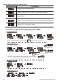
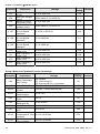
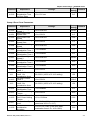
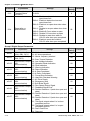
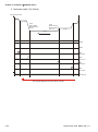
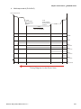
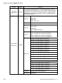
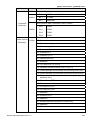
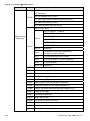
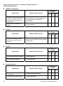
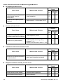
Chapter 4 Parameters|VFD-M-D Series
Parameter
Explanation
0-10
PWM Carrier
Frequency
Selections
0-11
AVR Function
0-12
Source of
Operation
Command
0-13
Stop Method
0-14
Door Open/Close
Control
0-15
Position Mode
0-16
Fan Control
0-17
0-18
Settings
01~15 kHz
Factory
Customer
Setting
12
00: AVR function enable
01: AVR function disable
02: AVR function disable for decel.
00: Digital keypad
01: External terminals. Keypad STOP enabled.
02: External terminals. Keypad STOP disabled.
03: RS-485 serial communication (RJ-11).
Keypad STOP enabled.
04: RS-485 serial communication (RJ-11).
Keypad STOP disabled.
00: Ramp to stop
01: Coast to stop
00: Enable door open/close operation
01: Disable door open operation
02: Disable door close operation
00: No limit signal, detected by PG number or
current level
01: Door open limit signal only, door close limit
is detected by PG number or current level
02: Door close limit signal only, door open limit
is detected by PG number or current level
03: Door open and close limit signal
04: Detect by PG number and also accept
external door open/close limit signal
00: Always fan on
01: Drive stops 1 minute later, fan stop running
02: Run and fan on, stop and fan off
03: Preliminary temperature attained, fan start
to run (when temperature is equal or higher
than 60 oC, it runs. When it is less than 40
o
C, it stops.
Stall Current Level
0.0~200.0%
of Position Mode
00: V/F control
Control Methods
01: Vector Control
00
00
00
00
00
03
30.0
00
Group 1 Basic Parameters
Parameter
1-00
1-01
1-02
Explanation
Maximum Output
Frequency (Fmax)
Maximum Voltage
Frequency (Fbase)
Maximum Output
Voltage (Vmax)
Revision May 2009, MDE5, SW V1.1
Settings
Factory
Customer
Setting
50.00 to 400.0 Hz
60.00
0.10 to 400.0 Hz
60.00
230V series: 0.1V to 255.0V
220.0
4-3