1
Laboratory Exercise 7
Finite State Machines
This is an exercise in using finite state machines.
Part I
We wish to implement a finite state machine (FSM) that recognizes two specific sequences of applied input symbols, namely four consecutive 1s or four consecutive 0s. There is an input w and an output z. Whenever w = 1 or
w = 0 for four consecutive clock pulses the value of z has to be 1; otherwise, z = 0. Overlapping sequences are
allowed, so that if w = 1 for five consecutive clock pulses the output z will be equal to 1 after the fourth and fifth
pulses. Figure 1 illustrates the required relationship between w and z.
Clock
w
z
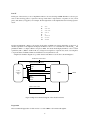
Figure 1: Required timing for the output z.
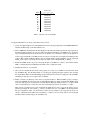
A state diagram for this FSM is shown in Figure 2. For this part you are to manually derive an FSM circuit that
implements this state diagram, including the logic expressions that feed each of the state flip-flops. To implement
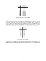
the FSM use nine state flip-flops called y8 , . . . , y0 and the one-hot state assignment given in Table 1.
Reset
A/0
w=0
w=1
1
B/0
F/0
0
w=0
1
1
0
G/0
C/0
w=0
D/0
1
0
1
0
w=0
0
1
H/0
1
E/1
I/1
Figure 2: A state diagram for the FSM.
1
1
Name
State Code
y8 y7 y6 y5 y4 y3 y2 y1 y0
A
B
C
D
E
F
G
H
I
000000001
000000010
000000100
000001000
000010000
000100000
001000000
010000000
100000000
Table 1: One-hot codes for the FSM.
Design and implement your circuit on the DE1 board as follows:
1. Create a new Quartus II project for the FSM circuit. Select as the target chip the Cyclone II EP2C20F484C7,
which is the FPGA chip on the Altera DE1 board.
2. Write a VHDL file that instantiates the nine flip-flops in the circuit and which specifies the logic expressions
that drive the flip-flop input ports. Use only simple assignment statements in your VHDL code to specify the
logic feeding the flip-flops. Note that the one-hot code enables you to derive these expressions by inspection.
Use the toggle switch SW0 on the DE1 board as an active-low synchronous reset input for the FSM, use SW1
as the w input, and the pushbutton KEY0 as the clock input which is applied manually. Use the green light
LEDG0 as the output z, and assign the state flip-flop outputs to the red lights LEDR8 to LEDR0 .
3. Include the VHDL file in your project, and assign the pins on the FPGA to connect to the switches and the
LEDs, as indicated in the User Manual for the DE1 board. Compile the circuit.
4. Simulate the behavior of your circuit.
5. Once you are confident that the circuit works properly as a result of your simulation, download the circuit
into the FPGA chip. Test the functionality of your design by applying the input sequences and observing
the output LEDs. Make sure that the FSM properly transitions between states as displayed on the red LEDs,
and that it produces the correct output values on LEDG0 .
6. Finally, consider a modification of the one-hot code given in Table 1. When an FSM is going to be implemented in an FPGA, the circuit can often be simplified if all flip-flop outputs are 0 when the FSM is in the
reset state. This approach is preferable because the FPGA’s flip-flops usually include a clear input, which
can be conveniently used to realize the reset state, but the flip-flops often do not include a set input.
Table 2 shows a modified one-hot state assignment in which the reset state, A, uses all 0s. This is accomplished by inverting the state variable y0 . Create a modified version of your VHDL code that implements
this state assignment. (Hint: you should need to make very few changes to the logic expressions in your
circuit to implement the modified state assignment.) Compile your new circuit and test it both through
simulation and by downloading it onto the DE1 board.
2
Name
State Code
y8 y7 y6 y5 y4 y3 y2 y1 y0
A
B
C
D
E
F
G
H
I
000000000
000000011
000000101
000001001
000010001
000100001
001000001
010000001
100000001
Table 2: Modified one-hot codes for the FSM.
Part II
For this part you are to write another style of VHDL code for the FSM in Figure 2. In this version of the code
you should not manually derive the logic expressions needed for each state flip-flop. Instead, describe the state
table for the FSM by using a VHDL CASE statement in a PROCESS block, and use another PROCESS block to
instantiate the state flip-flops. You can use a third PROCESS block or simple assignment statements to specify the
output z. To implement the FSM, use four state flip-flops y3 , . . . , y0 and binary codes, as shown in Table 3.
Name
State Code
y3 y2 y1 y0
A
B
C
D
E
F
G
H
I
0000
0001
0010
0011
0100
0101
0110
0111
1000
Table 3: Binary codes for the FSM.
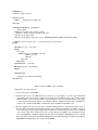
A suggested skeleton of the VHDL code is given in Figure 3. Observe that the present and next state vectors for
the FSM are defined as an enumerated type with possible values given by the symbols A to I. The VHDL compiler
determines how many state flip-flops to use for the circuit, and it automatically chooses the state assignment.
3
LIBRARY ieee;
USE ieee.std_logic_1164.all;
ENTITY part2 IS
PORT ( . . . define input and output ports
. . .);
END part2;
ARCHITECTURE Behavior OF part2 IS
. . . declare signals
TYPE State_type IS (A, B, C, D, E, F, G, H, I);
– Attribute to declare a specific encoding for the states
attribute syn_encoding : string;
attribute syn_encoding of State_type : type is "0000 0001 0010 0011 0100 0101 0110 0111 1000";
SIGNAL y_Q, Y_D : State_type; - - y_Q is present state, y_D is next state
BEGIN
...
PROCESS (w, y_Q) - - state table
BEGIN
case y_Q IS
WHEN A IF (w = ’0’) THEN Y_D <= B;
ELSE Y_D <= F;
END IF;
. . . other states
END CASE;
END PROCESS; - - state table
PROCESS (Clock) - - state flip-flops
BEGIN
...
END PROCESS;
. . . assignments for output z and the LEDs
END Behavior;
Figure 3: Skeleton VHDL code for the FSM.
Implement your circuit as follows.
1. Create a new project for the FSM.
2. Include in the project your VHDL file that uses the style of code in Figure 3. Use the toggle switch SW0
on the DE1 board as an active-low synchronous reset input for the FSM, use SW1 as the w input, and the
pushbutton KEY0 as the clock input which is applied manually. Use the green light LEDG0 as the output
z, and assign the state flip-flop outputs to the red lights LEDR3 to LEDR0 . Assign the pins on the FPGA to
connect to the switches and the LEDs, as indicated in the User Manual for the DE1 board.
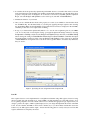
3. Before compiling your code it is necessary to explicitly tell the Synthesis tool in Quartus II that you wish to
have the finite state machine implemented using the state assignment specified in your VHDL code. If you
do not explicitly give this setting to Quartus II, the Synthesis tool will automatically use a state assignment
of its own choosing, and it will ignore the state codes specified in your VHDL code. To make this setting,
choose Assignments > Settings in Quartus II, and click on the Analysis and Synthesis item on the left
side of the window, then click on the More Setting button. As indicated in Figure 4, change the parameter
State Machine Processing to the setting User-Encoded.
4
4. To examine the circuit produced by Quartus II open the RTL Viewer tool. Double-click on the box shown
in the circuit that represents the finite state machine, and determine whether the state diagram that it shows
properly corresponds to the one in Figure 2. To see the state codes used for your FSM, open the Compilation
Report, select the Analysis and Synthesis section of the report, and click on State Machines.
5. Simulate the behavior of your circuit.
6. Once you are confident that the circuit works properly as a result of your simulation, download the circuit
into the FPGA chip. Test the functionality of your design by applying the input sequences and observing
the output LEDs. Make sure that the FSM properly transitions between states as displayed on the red LEDs,
and that it produces the correct output values on LEDG0 .
7. In step 3 you instructed the Quartus II Synthesis tool to use the state assignment given in your VHDL
code. To see the result of removing this setting, open again the Quartus II settings window by choosing
Assignments > Settings, and click on the Analysis and Synthesis item, then click on the More Setting
button. Change the setting for State Machine Processing from User-Encoded to One-Hot. Recompile
the circuit and then open the report file, select the Analysis and Synthesis section of the report, and click
on State Machines. Compare the state codes shown to those given in Table 2, and discuss any differences
that you observe.
Figure 4: Specifying the state assignment method in Quartus II.
Part III
The sequence detector can be implemented in a straightforward manner using shift registers, instead of using
the more formal approach described above. Create VHDL code that instantiates two 4-bit shift registers; one is
for recognizing a sequence of four 0s, and the other for four 1s. Include the appropriate logic expressions in your
design to produce the output z. Make a Quartus II project for your design and implement the circuit on the DE1
board. Use the switches and LEDs on the board in a similar way as you did for Parts I and II and observe the
behavior of your shift registers and the output z. Answer the following question: could you use just one 4-bit shift
register, rather than two? Explain your answer.
5
Part IV
In this part of the exercise you are to implement a Morse-code encoder using an FSM. The Morse code uses patterns of short and long pulses to represent a message. Each letter is represented as a sequence of dots (a short
pulse), and dashes (a long pulse). For example, the first eight letters of the alphabet have the following representation:
A
B
C
D
E
F
G
H
•—
—•••
—•—•
—••
•
••—•
——•
••••
Design and implement a Morse-code encoder circuit using an FSM. Your circuit should take as input one of
the first eight letters of the alphabet and display the Morse code for it on a red LED. Use switches SW2−0 and
pushbuttons KEY1−0 as inputs. When a user presses KEY1 , the circuit should display the Morse code for a letter
specified by SW2−0 (000 for A, 001 for B, etc.), using 0.5-second pulses to represent dots, and 1.5-second pulses
to represent dashes. Pushbutton KEY0 should function as an asynchronous reset.
A high-level schematic diagram of a possible circuit for the Morse-code encoder is shown in Figure 5.
Pushbuttons and switches
Morse code length counter
Data
Enable
Load
Letter
selection
logic
FSM
Morse code shift register
Data
Enable
Load
Half-second counter
Figure 5: High-level schematic diagram of the circuit for Part IV.
Preparation
The recommended preparation for this exercise is to write VHDL code for Parts I through IV.
6
LEDR0
c
Copyright 2011
Altera Corporation.
7