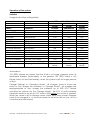
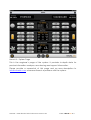
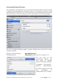
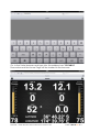
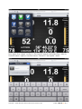
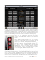
1
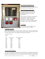
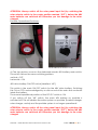
User manual – 2013 SEDT Systems Motu
Manual – Solar Electric Drive Train Motu 2013 rev.03
© 2014 Naval DC B.V.
VERY IMPORTANT:
THE ONBOARD SYSTEM MUST NOT BE TEMPERED WITH,
CHANGED OR MISSUSED IN ANY WAY. ALWAYS CONTACT
THE SYSTEM DESIGNER AT NAVAL DC B.V. FIRST, IF YOU
HAVE QUESTIONS ABOUT THE SYSTEM OR WOULD LIKE TO
CHANGE OR REPLACE ANY OF ITS COMPONENTS.
You can reach Naval DC B.V. via email:
[email protected]
Manual – Solar Electric Drive Train Motu 2013 rev.03
© 2014 Naval DC B.V.
General system overview:
Rangi has two independent solar electric drive systems, one per hull. Each
system consist of the following main components:
!
!
!
!
!
!
!
!
!
4 x solar panels (PS), 4 x solar panels (SB)
1 x solar charger (Variotrack)
1 x inverter / charger (Xtender) [12A charger – 700W inverter]
1 x 48V LiPo battery system (15.5 kWh)
1 x DC-distribution (fuse-holder)
1 x battery bridge cable with HV connectors
1 x solar selector 3-position switch
1 x motor controller
1 x AC 3~ PMS 10kW inboard motor
Starboard carries the following additional components:
! 1 x DC-DC 48-13.8V converter (22A)
! 1 x Naval UI data system (PC, Wifi AP, CAN adapter, Studer adapter,
USB hub, SIM Modem for the Naval UI internet uplink)
! 1 x 12V fuse-box for PC, AP, Hub and 12V connection
The 12V service battery is positioned in the starboard hull, as well:
! 1 x 12V PB battery 105Ah
! 1 x Naval UI digital 12V shunt
! 2 x 12V Solar inverter
! 1 x 12V fuse-box for 12V supply starboard system, data busses,
batteries and solar charge inputs. These are the permanent 12V users!
! 1 x main 12V automatic breaker to fuse the supply to the deckhouse
panel
!
!
!
!
!
!
!
!
!
Common components in the deckhouse:
1 x twin-throttle
1 x iPad Naval UI system display
1 x BEP 12V main breaker panel with 12V meter
1 x Main 12V switch to isolate the BEP 12V main breaker panel
1 x analogue 48V meter (45-60V) from each hull
1 x motor ON/OFF switch from each hull
1 x shore power inlet from each hull
1 x AC 220V 50Hz outlet from each hull
2 x 100W flexible solar panel on the cabin top
Manual – Solar Electric Drive Train Motu 2013 rev.03
© 2014 Naval DC B.V.
Operation panel (deckhouse):
The operation panel in the deckhouse
with the its main components:
- BEP 12V main breaker panel:
This panel switches all vessel and
navigation related 12V users. The
following breakers need further
explanation:
LPG control = LPG sniffer in the galley
Instruments = iPad power supply
Accessories = Fans in front cabins
Freezer = DC outlet for fridge
DC outlets = 3x 12V outlet (at bottom)
Spotlight = search light outlet (right)
- 12V Feed:
This breaker isolates the BEP panel
from the 12V service battery."
- Analogue V meters:
With these panel meters, the most basic system status can be determined.
When crosschecking the voltage with the SOC table, please always make
sure that the motor is not running when taking the reading.
Voltage no load
table:
SOC
0%
10%
20%
30%
40%
50%
60%
70%
80%
90%
100%
Volts per cell
3.490
3.556
3.608
3.648
3.681
3.723
3.783
3.867
3.959
4.057
4.180
Volts per battery
48.86
49.78
50.51
51.07
51.53
52.12
52.96
54.14
55.43
56.80
58.52
- Motor ON/OFF switches:
This switch switches the internal motor controller relay and therefore supplies
the motor controller with 48V. The boat is ready for operation when these
switches are switched on, given that the main 48V drive batteries are
Manual – Solar Electric Drive Train Motu 2013 rev.03
© 2014 Naval DC B.V.
switched on and charged. Switching the motors on or off is acknowledged
by a click sound that the main line contactor makes inside the motor
controller.
Starboard Operational Switches:
Three operational switches STB
Solar selector switch STB
A) The top revision cover on the starboard reveals the three operational
switches. All these switches follow the same switching pattern:
vertical = OFF
horizontal = ON
The mounted switches have the following function:
1. top: DC-DC switch [labelled: “DC-DC”]
This switches the 48V-13.8V dc-dc converter on, which supplies the
little 12V fuse-box mounted in the starboard system with 13.8V and
charges therefore the 12V service battery, if the middle 12V switch
[labelled: “12”] is switched on, as well.
The normal operational position of the DC-DC switch is: ON
2. middle: 12V service battery switch [labelled: “12”]
This switch connects or isolates the 12V service battery to and from
the permanent 12V users such as the Naval UI data read out system
(PC, AP, Hub) and the starboard mounted dc-dc converter.
The normal operational position of the DC-DC switch is: ON
3. bottom: 48V drive battery ON/OFF switch [labelled: “48”]
Manual – Solar Electric Drive Train Motu 2013 rev.03
© 2014 Naval DC B.V.
This switch is the main ON/OFF switch for the 48V drive battery.
Switching this ON or OFF is acknowledged by a click sound of the
main line contactor inside the battery.
The normal operational position of the DC-DC switch is: ON
During normal operation the three switches have the following positions:
1. “DC-DC” = ON
2. “12” = ON
3. “48” = ON
If you switch off the “DC-DC” switch, the 12V battery system will not be
charged anymore by the dc-dc converter (given that “12” is switched on).
Furthermore, the Naval UI data system will not be supplied anymore by the
dc-dc converter and will therefore only run on the 12V service battery.
ATTENTION: The “DC-DC” switch must always be switched on; otherwise the
12V service battery will be undercharged and destroyed!
If you switch off the “12” switch, the 12V service battery is no longer
connected to the starboard system. The 12V service battery can therefore
no longer be charged (given that “DC-DC” is switched on) and can no
longer supply the Naval UI data system. The Naval UI system will therefore
stop working, if both switches, “DC-DC” & “12” are switched off!
Important: restarting the Naval UI data system is done by switching the
switches “DC-DC” and “12” off and back on again!
ATTENTION: The “12” switch must always be switched on; otherwise the 12V
service battery will be depleted and destroyed!
If you switch off the “48” switch, the main 48V battery on starboard is
switched off! This will disable the entire system on starboard
(inverter/charger, solar-charger, motor, dc-dc converter) and the starboard
system is no longer operational!
ATTENTION: Always switch off the solar panel input first (by switching the
solar selector switch to the center position marked “OFF”), before the 48V
main batteries are switched off! Otherwise you risk damage to the solarcharger!
B) The bottom revision cover on the starboard system reveals the solar
selector switch. By means of this switch, the four solar panels on the right
half of the solar array can be distributed to:
1. the starboard system = switch the lever to the right “STB” position
This is the standard setting for the starboard solar selector switch!
2. the panels are isolated and not connected to anything by
switching the lever to the vertical “OFF” position.
3. the portside system = switch the lever to the left “PORT” position.
This is the optional setting to connect the starboard four solar
panels to the portside system.
Manual – Solar Electric Drive Train Motu 2013 rev.03
© 2014 Naval DC B.V.
ATTENTION: Always switch off the solar panel input first (by switching the
solar selector switch to the center position marked “OFF”), before the 48V
main batteries are switched off! Otherwise you risk damage to the solarcharger!
Portside Operational Switches:
48V battery switch PORT
Solar selector switch PORT
A) The top revision cover on the starboard reveals 48V battery main switch.
The switch follows the same switching pattern:
vertical = OFF
horizontal = ON
48V drive battery ON/OFF switch [labelled: “48”]
This switch is the main ON/OFF switch for the 48V drive battery. Switching
this ON or OFF is acknowledged by a click sound of the main line contactor
inside the battery.
The normal operational position of the DC-DC switch is: ON
If you switch off the “48” switch, the main 48V battery on portside is
switched off! This will disable the entire system on portside (inverter/charger,
solar-charger, motor) and the portside system is no longer operational!
ATTENTION: Always switch off the solar panel input first (by switching the
solar selector switch to the center position marked “OFF”), before the 48V
main batteries are switched off! Otherwise you risk damage to the solarcharger!
Manual – Solar Electric Drive Train Motu 2013 rev.03
© 2014 Naval DC B.V.
B) The bottom revision cover on the portside system reveals the solar
selector switch. By means of this switch, the four solar panels on the left half
of the solar array can be distributed to:
1. the portside system = switch the lever to the left “PORT” position
This is the standard setting for the portside solar selector switch!
2. the panels are isolated and not connected to anything by
switching the lever to the vertical “OFF” position.
3. the starboard system = switch the lever to the right “STB” position.
This is the optional setting to connect the portside four solar panels
to the starboard system.
ATTENTION: Always switch off the solar panel input first (by switching the
solar selector switch to the center position marked “OFF”), before the 48V
main batteries are switched off! Otherwise you risk damage to the solarcharger!
Battery cross connection cable:
Starboad cross over connection
Portside cross over connection
There is a 48V cross cable in place that can link either side’s 48V system to
the other system, in case this might be needed. The cross connection cable
is standard not plugged in and the two outer end connectors are labelled
“BATT LINK”. Furthermore, each system has a matching connector from the
48V battery labelled “MAIN BATT” (this is coming from the 48V battery and
supplies 48V) and another one connected to the systems’ 48V DC-busbar
labelled “STB SYSTEM” or “PORT SYSTEM”, respectively.
DANGER: EXTRA CARE HAS TO BE TAKEN WHEN USING THE CROSS
CONNECTION CABLE. FOLLOW THE STEPS BELOW CAREFULLY AND ALWAYS
DOUBLE CHECK FOR CORRECTES OF YOUR ACTIONS! LIFE THREATENING
INJURIES AND DEATH CAN BE THE CONSEQUENCE OF WRONG HANDLING!!!
Manual – Solar Electric Drive Train Motu 2013 rev.03
© 2014 Naval DC B.V.
The following connection scenarios can be done:
1) Normal operation scenario:
a. “BATT LINK” is not plugged into anything on both sides
b. “MAIN BATT” from STB is plugged into “STB SYSTEM”
c. “MAIN BATT” from PORT is plugged into “PORT SYTEM”
This is the normal operational scenario and the STB battery will supply
the STB users or chargers, such as the motor, inverter/charger and
solar charger. The PORT battery will supply the PORT users or chargers,
such as the motor, inverter/charger and solar charger.
2) Link the STB 48V battery to the PORT system
a. Switch off both motors in the deckhouse
b. Switch off both solar selector switches
c. Switch off the dc-dc converter via the switch “DC-DC” in the
STB system
d. Switch off the 12V supply to the Naval UI data system via the
switch “12” in the STB system
e. Switch off both 48V batteries via the switches “48” in both
systems
f. Disconnect the connectors “STB SYSTEM” and “MAIN BATT” in
the STB system
g. Disconnect the connectors “PORT SYSTEM” and “MAIN BATT” in
the PORT system
h. Connect the “BATT LINK” connector to the “MAIN BATT”
connector in the STB system
i. Connect the “BATT LINK” connector to the “PORT SYSTEM”
connector in the PORT system
j. Switch on the STB 48V battery via the switch “48” in the STB
system
k. Leave the PORT 48V battery switched off, as it is not connected
to anything anymore
l. Switch both solar selector switches to PORT, as only the PORT
solar charger is now connected to the STB battery
m. Switch on the PORT motor via the switch in the deckhouse and
leave the STB motor switched off
n. If you want to charge the STB battery in this scenario via shore
power, you will have to use the PORT shore power plug
This scenario is only used when the PORT motor has to run off the STB
battery. E.g. when the STB motor is broken and you want to use the
energy from the STB battery to run the PORT motor.
IMPORTANT: Please note that the voltage of the STB 48V battery is now
displayed on the PORT analogue voltage panel meter in the
deckhouse!
ATTENTION: Prolonged operation of this scenario will deplete and
damage the 12V service battery, as the starboard mounted dc-dc
Manual – Solar Electric Drive Train Motu 2013 rev.03
© 2014 Naval DC B.V.
converter can no longer supply a charge to the service battery. Only
the deckhouse solar panels are charging the service battery in this
scenario. The Naval UI data system is not operational in this scenario,
unless you switch on the 12V supply from the service battery to the
Naval UI system via the switch “12” in the STB system. However, this
will deplete the 12V service battery even faster! You must minimize
the 12V users as much as possible! The health of the 12V battery must
be closely monitored via the BEP deckhouse panel 12V analogue
meter. The 12V battery must not be further discharged than 11V
maximum to prevent permanent damage.
3) Link the PORT 48V battery to the STB system
a. Switch off both motors in the deckhouse
b. Switch off both solar selector switches
c. Switch off the dc-dc converter via the switch “DC-DC” in the
STB system
d. Leave the 12V supply to the Naval UI data system via the
switch “12” in the STB system switched on
e. Switch off both 48V batteries via the switches “48” in both
systems
f. Disconnect the connectors “PORT SYSTEM” and “MAIN BATT” in
the PORT system
g. Disconnect the connectors “STB SYSTEM” and “MAIN BATT” in
the STB system
h. Connect the “BATT LINK” connector to the “MAIN BATT”
connector in the PORT system
i. Connect the “BATT LINK” connector to the “STB SYSTEM”
connector in the STB system
j. Switch on the PORT 48V battery via the switch “48” in the PORT
system
k. Leave the STB 48V battery switched off, as it is not connected
to anything anymore
l. Switch both solar selector switches to STB, as only the STB solar
charger is now connected to the PORT battery
m. Switch on the dc-dc converter in STB via the switch “DC-DC” in
the STB system
n. Switch on the STB motor via the switch in the deckhouse and
leave the PORT motor switched off
o. If you want to charge the PORT battery in this scenario via
shore power, you will have to use the STB shore power plug
This scenario is only used when the STB motor has to run off the PORT
battery. E.g. when the PORT motor is broken and you want to use the
energy from the PORT battery to run the STB motor.
IMPORTANT: Please note that the voltage of the PORT 48V battery is
now displayed on the STB analogue voltage panel meter in the
deckhouse!
Manual – Solar Electric Drive Train Motu 2013 rev.03
© 2014 Naval DC B.V.
ATTENTION: The Naval UI data system is operational in this scenario,
and charging of the 12V service battery also works! However, you
have to make sure that the dc-dc converter is switched on via the
switch “DC-DC” in the STB system. The switch “12” must also remain to
be switched on in the STB system, otherwise the charge from the dcdc converter cannot reach the 12V service battery.
DANGER: YOU MUST NEVER CONNECT THE TWO 48V BATTERIES TOGETHER BY
LINKING THE “BATT LINK” CONNECTOR ON EACH SIDE TO THE “MAIN BATT”
CONNECTOR! LIFE THREATENING INJURIES AND DEATH CAN BE THE
CONSEQUENCE OF WRONG HANDLING!!! DANGER OF EXPLOTION AND FIRE!!!
DANGER: YOU MUST NEVER CONNECT THE TWO SYSTEMS TOGETHER BY
LINKING THE “BATT LINK” CONNECTOR ON EACH SIDE TO THE “STB SYSTEM”
CONNECTOR IN STB AND THE “PORT CONNECTOR” IN PORT! LIFE
THREATENING INJURIES AND DEATH CAN BE THE CONSEQUENCE OF WRONG
HANDLING!!! DANGER OF EXPLOTION AND FIRE!!!
Manual – Solar Electric Drive Train Motu 2013 rev.03
© 2014 Naval DC B.V.
Operation of the system:
Switches
Usage Modi Switch-setting Matrix:
Different Modi Switch Positions:
Switch
Location
Vessel
docked
Vessel
operational
Vessel
stored
< three weeks
Motor PORT
Motor STB
12V FEED
Deckhouse
Deckhouse
Deckhouse
OFF
OFF
ON
ON
ON
ON
OFF
OFF
OFF
DC-DC
12V Link
48V Battery STB
STB Solar Selector
STB System
STB System
STB System
STB System
ON
ON
ON
STB
ON
ON
ON
STB
ON
ON
ON
STB
48V Battery PORT
STB Solar Selector
PORT System
PORT System
ON
PORT
ON
PORT
ON
PORT
12V auto breaker
outside 12V comp.
ON
ON
ON
Charger Settings
4th page Naval UI - iPad
Operation
Mode
Operation
Mode
Storage
Mode
Annotations:
12V FEED: please be aware that the iPad is no longer charged when its
dedicated breaker (Instruments) or the general 12V FEED switch is off!
Please switch off the iPad entirely, when the system is left for longer periods
of time.
Charger Settings: in “Operation Mode”, all chargers (solar & shore) are
setup to fully charge the batteries. In “Storage Mode”, all chargers are
reprogrammed to only charge the batteries up to 50% SOC. Before
switching the system into the “Storage Mode”, the SOC of both batteries
therefore needs to be at an SOC below 50% before the button is pressed.
When the vessel is left in storage mode, either both shore power chargers
need to be plugged in, or the boat needs to be left in the sun (i.e. do not
cover the rear solar array!).
Manual – Solar Electric Drive Train Motu 2013 rev.03
© 2014 Naval DC B.V.
Switching off the entire system:
Use the following procedure to switch off the systems entirely. Use this
procedure when the vessel is not used for periods in excess of three weeks.
Before switching off the entire system, please follow these instructions:
1) make sure the 48V batteries are charged/discharged to 50% SOC
2) set all operational switches according to the following positions:
Different Modi Switch
Positions:
Switch
Location
Switching
Order
Vessel
stored
> three weeks
iPad - Display
Motor PORT
Motor STB
12V FEED
STB Solar Selector
STB Solar Selector
DC-DC
12V Link
48V Battery STB
48V Battery PORT
12V auto breaker
Deckhouse
Deckhouse
Deckhouse
Deckhouse
STB System
PORT System
STB System
STB System
STB System
PORT System
outside 12V comp.
1
2
3
4
5
6
7
8
9
10
11
Switch off
OFF
OFF
OFF
OFF
OFF
OFF
OFF
OFF
OFF
OFF
When everything is switched off, two things will stay active:
1) the 12V service battery will still be charged by the deckhouse solar
panels. This will preserve the service batteries charge.
2) the 48V batteries BMS will be kept alive by the 12V service battery to
balance the 48V battery cells.
When the vessel is made operational again, please follow the table above
in reverse order to make everything operational again.
IMPORTANT: When the system is switched off completely, please check
every two weeks that the 48V batteries are around the 50% SOC mark. Ad
charge or discharge if necessary to bring the SOC to the 50% SOC mark
again. Keep a log of these measurements with SOC value and date! The
SOC-value can be checked by making the vessel operational again and
reading the values from the Naval UI (iPad). An alternative way is to just
switch on the 48V battery and check the analogue voltmeters in the
deckhouse (52V equals 50% SOC!).
FYI: It will take at least 2 minutes after switching everything on before the
on-board PC can display the data on the Naval UI System (iPad).
Manual – Solar Electric Drive Train Motu 2013 rev.03
© 2014 Naval DC B.V.
Components
Battery: 15kWh lithium polymer battery, 48V. Do not load the batteries with
more than 200A current!
Inverter / Charger (Xtender): 700W 220VAC 50Hz inverter / 12A 48V shore
power. The shore power charger requires a 220V 50Hz outlet to operate. Do
not connect to 110V 60Hz grids!
The chargers charge current can be configured via the 4th Naval UI page
on the iPad. The standard setting is 12A and can be decreased and
increased again between 1A and 12A in steps of 1A.
Solar charger (Variotrack): 980W solar charger.
Motor & Controller: 10kW PM Synchronous inboard electric motor
Fuses
48V Main fuses in the DC-distribution:
Inverter / Charger
50A ANL Fuse
Battery Feed
250A ANL Fuse
Motor Feed
250A ANL Fuse
Solar Charger
50A ANL Fuse
DC-DC Feed
10A Blade Fuse
12V Fuses STB System:
#3 in: DC-DC Feed
#4 out: PC
#5 out: USB Hub
#6 out: Wifi AP
30A Blade Fuse
5A Blade Fuse
5A Blade Fuse
3A Blade Fuse
The main plus lead is coming fused from the 12V
battery!
12V Compartment Fuses:
#1 12V supply to LiPo batteries
#2 12V link to STB 12V system
#3 12V supply to NMEA2000 bus
#4 PORT 12V solar panel charger
#5 STB 12V solar panel charger
#6 12V shunt supply
20A Blade Fuse
25A Blade Fuse
5A Blade Fuse
15A Blade Fuse
15A Blade Fuse
1-2A Blade Fuse
"
Attention: Only use the same rated fuse when replacing a blown one!
Manual – Solar Electric Drive Train Motu 2013 rev.03
© 2014 Naval DC B.V.
Naval UI
The Naval UI is a system wide alarm & monitoring data read-out system,
that is displayed on the deckhouse mounted iPad. Is it used to daily monitor
and control the entire solar electric drive train system.
Naval UI – Homepage
This is the standard page of the system. It shows the most vital data of the
drive train system.
Functionality:
•
•
•
•
Night mode button (bottom left) = changes the interface into a
black/red version of the current page
Page buttons (bottom center) = direct links to the Home, GPS &
System pages
Anchor icon = Homepage
Satellite icon = GPS or Sailing page
Battery icon = System page
Naval DC Logo (bottom right) = Setup for units and capacities
Arrow buttons (top left & right corners) = go left, go right to cycle
through the pages.
Manual – Solar Electric Drive Train Motu 2013 rev.03
© 2014 Naval DC B.V.
Naval UI – GPS Page
This can be used whenever pure sailing related information is desired.
Manual – Solar Electric Drive Train Motu 2013 rev.03
© 2014 Naval DC B.V.
Naval UI – System Page
This is the engineer’s page of the system. It provides in-depth data for
precise information analyses, error tracing and support information.
Please provide a screenshot of this page and an error description to
[email protected] whenever there is a problem with the system.
Manual – Solar Electric Drive Train Motu 2013 rev.03
© 2014 Naval DC B.V.
Naval UI – Charger Information Page
This 4th page cannot be accessed via a direct page link button. To access
this page, go right with the arrow button when on the System Page, or go
left with the arrow button when on the Home Page.
Via this page, the inverter/chargers can be switched on or off per system
and the shore power battery charger power can be adjusted between 1A
& 12A in incremental or decremental steps of 1A. This functionality is used
when the charger is plugged into a low fused output, however 12A already
is a light load for most 220V outputs. The battery charge current settings
should therefor be left at 12A as standard setting and only changed when
really needed.
Charger Settings: the standard setting is Operation Mode.
In “Operation Mode”, all chargers (solar & shore) are setup to fully charge
the batteries. In “Storage Mode”, all chargers are reprogrammed to only
charge the batteries up to 50% SOC. Before switching the system into the
“Storage Mode”, the SOC of both batteries therefore needs to be at an
SOC below 50% before the button is pressed. When the vessel is left in
storage mode, either both shore power chargers need to be plugged in, or
the boat needs to be left in the sun (i.e. do not cover the rear solar array!).
Attention: The chargers remember the last setting, until another mode
button is pressed.
Manual – Solar Electric Drive Train Motu 2013 rev.03
© 2014 Naval DC B.V.
Accessing the Naval UI System
Any portable or fixed device can access the Naval UI system with a browser.
It works across all platforms, however until now, the Naval UI system is fully
optimized for iOS devices. Up to five devices can simultaneously access the
Naval UI system. The following instructions are based on an iPad example:
Go to the wireless settings page in system settings and choose the vessels
wireless network:
Rangi’s network name is:
The password is:
NavalUIOkeanos 2
Okeanos2 (make sure it is a capital “O”)
For the iPad in the
deckhouse, please use
the static IP address
option with these settings:
IP address: 192.168.0.50
Subnet:
255.255.255.0
All other devices can use
the
automatic
IP
assignment DHCP setting.
Manual – Solar Electric Drive Train Motu 2013 rev.03
© 2014 Naval DC B.V.
Go to the Safari browser and type into the address bar: 192.168.0.1
Press enter and the Home Page will be loaded in the browser:
Manual – Solar Electric Drive Train Motu 2013 rev.03
© 2014 Naval DC B.V.
Now press the “share” button in the top left corner and press the “Add to
Home Screen” option. Use the name “Naval UI” and press “Add”.
Manual – Solar Electric Drive Train Motu 2013 rev.03
© 2014 Naval DC B.V.
This will add a Naval UI icon to the screen. Press and hold the Naval UI icon
until it starts to wiggle. Now drag the icon into the dock area.
When the Naval UI icon is now pressed, the Naval UI system will start as a
‘web-app’, i.e. as a full screen application:
Manual – Solar Electric Drive Train Motu 2013 rev.03
© 2014 Naval DC B.V.
In case the Naval UI does not show any numbers and just displays
“undefined” (like pictures above in the System Page example), it needs to
be restarted. Another reason to restart the Naval UI system would be, if the
screen is just showing a white page with the text “please start the program
Connector”. Restarting the Naval UI system is done in the following way:
Go to the STB system and open the top revision
cover to access the three switches in the starboard
system.
Switch off the switches “DC-DC” and “12” to switch
off any 12V supply to the Naval UI PC system. This will
switch off the PC, Hub, AP and all Data adapters.
Wait for 10 seconds. Now switch both switches “DCDC” and “12” back on again. The PC will boot and
beep several times, so will the AP. Wait for at least 2
minutes, before trying to access the Naval UI system
on the iPad again, after a complete restart.
Other faulty behaviour can be when the Naval UI interface does not load
and a “Cancel or Retry” dialogue is shown with the Naval UI background
screen just showing. Press retry several times, until the system comes up. If it
does not come up after several attempts, follow the restarting steps above.
Manual – Solar Electric Drive Train Motu 2013 rev.03
© 2014 Naval DC B.V.
Daily usage
Throttle:
Always check that the throttle is in neutral before operating any motor
switches!
By switching the motors on via the Motor ON/OFF switches in the deckhouse,
the systems are ready for operation. This action is confirmed by a clicking
sound from the motor controller line contactor inside the respective motor
box. Additionally, the motor data from the switched on system will show up
on the System Page (3rd page) of the Naval UI read-out system on the iPad.
Reassure that the motors are operational in both directions by testing with
the throttle for a motor response while still docked.
Switching from neutral to FW or BW / or from one direction to the other one
should always be done in a controlled manner, so that the feathering
propeller has time to change from one blade position to the other one.
Whenever the propeller has to change direction, a clunking sound will be
the acknowledgement to listen for.
Regeneration:
The electric motors of the vessel can recharge the batteries when the vessel
is under sail. Generally, the regeneration with the propellers starts to work at
speeds of 7-8+ knots.
• Let the sails take over the propulsion of the vessel and reduce the
throttle to neutral.
• In order to use the motors as generators, the propellers must be
locked in the reverse propeller blade setting by shortly (and
decisively) moving the throttle into reverse and back to neutral again,
after the propeller makes that clunking sound. Not much power in
reverse is needed to lock the blades in this reverse position.
• Make sure that the shaft spins with the throttle in neutral again.
• Now slowly go into FW with the throttle, however stay below the point
where the motors would start taking over the propulsion of the vessel
from the sails again. Use the Naval UI battery ampere data to find the
optimum setting with the throttle. I.e. where the most amps are
regenerated.
Once you want to take control of the vessel again via the motors, just
increase the throttle more FW. The propeller will feather back into the FW
pitch setting and will propel the vessel.
Manual – Solar Electric Drive Train Motu 2013 rev.03
© 2014 Naval DC B.V.
AC 220V:
The AC inlets and outlets underneath the STB deckhouse bunk
Each inverter/charger has its own 220V inlet and outlet. The inverters are in
a standby mode when nothing is plugged in. Once a load is plugged in,
the inverters will automatically start putting out 220V.
Attention: Please be aware that the maximum continuous power output of
the inverters is 700W per inverter.
Manual – Solar Electric Drive Train Motu 2013 rev.03
© 2014 Naval DC B.V.
Internet Connection for Naval UI Data
The starboard system carries an Internet USB modem that is connected to
the Naval UI PC.
It is used to send the vessel data to the Naval DC for remote support and
system information purposes.
The monthly data usage requires a 1GB data plan. The required SIM factor
is the normal SIM card.
Whenever Rangi is in one country for longer periods of time, please get a
local contract data SIM card and put it in the USB modem. After that,
please reconnect the modem to the PC again and please make sure that
the modem is switched on again by pressing the on/off button for 3
seconds.
Manual – Solar Electric Drive Train Motu 2013 rev.03
© 2014 Naval DC B.V.
General explanation/advice:
Motors:
Keep the motor compartment clean and dry!
Important: Check the motor compartment on a daily basis for water ingress!
Danger: Water damage to the motors and motor controllers must be
avoided at all times!
Battery:
Important: Keep the batteries clean and dry!
The battery lifetime is preserved best, when the battery voltage is kept
around 52V (50% SOC). Therefore, always strive to cycle as close as possible
to the 50% mark and as little as possible. As mentioned above, it is vital that
when not used for longer periods, please get the batteries below 50% SOC
and then use the storage mode setting to keep the batteries at 50% SOC.
This and not storing them in temperatures above 25°C preserves the
batteries in the best possible way.
The systems have several safety mechanisms. When a low battery voltage is
reached (46V – under load), the motor controller will reduce the power of
the motor. The 220V inverter has its own under voltage safety feature and
will shut down automatically. In any case, recharge the battery and make
sure that all system loads (inverter, motor) are switched off. The battery must
not be depleted further beyond 50V (no load condition!). The batteries own
safety system will shut down the entire battery internally, at 42V (under
load!) or at other critical instances like over- or under-temperature and
when one cell’s values are too far off from the rest of the cells (V&T).
Basically this should never ever happen. If however this does occur, follow
these steps:
!
!
!
!
!
!
switch off the motor
switch off the solar breaker
switch off the main 48V batteries via the switch “48”
wait for 1 minute (the BMS needs to reset)
switch the main 48V battery back on again (listen for that clicking
sound from the main battery)
switch on the solar breaker
Verify that the batteries are online again (battery specific data is
displayed on the engineering page on the Naval UI (iPad)). Let the
batteries charge up again!
Manual – Solar Electric Drive Train Motu 2013 rev.03
© 2014 Naval DC B.V.
Safety considerations and fire precautions (Lithium Polymer batteries):
The batteries' internal BMS (battery management system) protects the
batteries from:
!
!
!
!
!
overcharge
undercharge (cut off = 2.75V/cell)
overtemperature (charging cut off = > 50˚C, discharging cut off = > 50˚C)
undertemperature (charging cut off = < 0˚C, discharging cut off = < -10˚C)
overcurrent (200A continous (300A for 30s))
The batteries are therefore completely controlled and protected by them
selves, as long as the external 12V BMS power supply is not interrupted.
A fire started by the batteries is very unlikely. In a test lab, if you want these
batteries to start a fire, you have to overcharge each individual cell (3.7V
nom.) to 12V. In your case, that would translate to an external voltage
source connected the batteries poles of 168V DC for a substantial amount
of time. FYI, the internal relay cuts out at a prolonged charging voltage of
58.8V.
If the batteries are on fire, then it will become a self-sustaining fire, as the
burning energy is provided by the battery itself (just like when a patrol tank
is on fire). Furthermore, toxic smoke is produced and released by the
batteries when burning.
DANGER & IMPORTANT: IN CASE OF FIRE INVOLVING OR NEAR THE LITHIUM
POLYMER BATTERIES, OR ELECTRIC FIRES, THE VESSEL MUST BE EVACUATED
IMMEDIATELY! DO NOT ATTEMPT TO EXTINGUISH AN ELECTRIC FIRE FOR
LONGER THAN 30 SECONDS. AFTER THIS TIME, IT IS HIGHLY UNLIKELY THAT IT
CAN BE EXTINGUISHED => ABANDON THE VESSEL IMMEDIATELY!!!
IMPORTANT: FREQUENT FIRE AND EVACUATION DRILLS WITH THE CREW ARE A
MUST IN ORDER TO SAFELY OPERATE THE VESSEL!!!
There are some measures to regulate and delay the fire, but once on fire,
they will have to burn out.
The batteries reactivity can be reduced or controlled, but not prevented
with the following extinguisher measures:
!
!
!
fire blanket around the batteries. This will buy you some extra time.
CO2 or Halon gas fire extinguishers (in both cases, the hulls must be
evacuated since both gases are heavier than air!). This will only
reduce the external oxygen to fuel the fire.
dry chemical or foam extinguishers. This will reduce the external
oxygen to fuel the fire.
Please carefully read the MSDS (material safety data sheet) for the lithium
polymer cells used.
Manual – Solar Electric Drive Train Motu 2013 rev.03
© 2014 Naval DC B.V.
Error tracing:
Charger (Studer Xtender)
If you do not see any charging amps from the shore power charger:
•
•
•
•
check the shore power cable connection
check whether the batteries are already fully charged
check the status LED’s on the charger
consult the charger’s manual
Inverter (Studer Xtender)
If the 220V inverter does not work:
•
•
•
check the status on the Naval UI or on the inverter/charger unit
make sure the inverter is switched on
consult the inverter manual
Solar Charger (Studer Variotrack)
If the solar charger is not working:
•
•
•
•
check the solar cable connections
check that the solar breaker is turned on (to its corresponding system)
check the status LED on the solar charger
consult the solar charger manual
Motor
If the motor does not work:
•
•
check all cable connections from the controller
use the handheld programmer in order to read out the error
messages in the monitor section. The handheld unit plugs into the PS
motor compartment 4pin plug.
Please consult the individual product manuals for more details!
Fuses: the main fuses are in the Mastervolt DC-Distribution
Manual – Solar Electric Drive Train Motu 2013 rev.03
© 2014 Naval DC B.V.
Contact:
For system questions, service and spare parts please contact
NAVAL DC B.V.
David Czap – [email protected]
Manual – Solar Electric Drive Train Motu 2013 rev.03
© 2014 Naval DC B.V.
MATERIAL SAFETY DATA SHEET
Section 1. Chemical Product And Company Identification
Product Name :
Superior Lithium Polymer Battery(SLPB)
Battery Type :
Rechargeable Battery
Description :
Lithium Cobalt Manganese Nickel Oxide
Model :
SLPB Series
Electrochemical System :
Negative Electrode : Carbon
Positive Electrode : Lithium Cobalt Manganese Nickel
Oxide (LiMnNiCoO2)
Electrolyte : Solution of lithium hexafluorophosphate
(LiPF6) in a mixture of organic solvent _
Ethylene Carbonate(EC) +
Ethymethyl Carbonate(EMC)
Nominal Voltage : 3.7V
Overall Chemical Reaction :
LixC + Li1-x
C + LiMnNiCoO2
Manufactured by :
Kokam Co., Ltd.
Address :
Head office : 1261-3 Jungwang-dong, Siheung-Si,
Kyunggi-Do, Korea 429-849 (Sihwa-Kongdan 2Na 304)
Factory : 483-42, Yachon-Ri, Gayakok-Myun, Nonsan-Si,
Chungnam, Korea 320-844
QA Manager: [email protected]
PE Manager: [email protected]
Emergency Telephone
Number :
CHEMTREC for Spills, Leaks, Fires
International :
1-703-527-3887
U.S.A :
1-800-424-9300
Technical Contact
Telephone Number :
82-31-362-0100
or
Date Prepared :
August 21, 2006
Date Reviewed :
December 12, 2008
Revision No :
5.0
Revision Date :
October 30, 2009
82-41-742-9221
Section 2. Hazards Identification
Kokam Co., Ltd.
Emergency overview:
Do not open or disassemble.
Do not expose to fire or open flame.
Do not mix with batteries of varying sizes, chemistries or types.
Do not puncture, deform incinerate or heat above 85
.
Potential health effects:
The materials contained in this battery may only represent a hazard if the integrity of the battery is
compromised or if the battery is physically or electrically abused.
(1) Physical:
The Lithium ion polymer rechargeable batteries described in this Material Safety Data Sheet are sealed
units which are not hazardous when used according to the recommendations of the Manufacturer.
Under normal conditions of use, the solid electrode materials and liquid electrolyte they contain are nonreactive provided the battery integrity is maintained and seals remain intact.
Risk of exposure is only in case of abuse (mechanical, thermal, electrical) leading to the activation of
safety valves and/or the rupture of the battery containers. Electrolyte leakage, electrode materials
reaction with moisture/water or battery vent/explosion/fire may follow, depending upon the
circumstances.
(2) Chemical :
Classification of dangerous substances contained into the product
As per directive 67/548/EEC
Substance
Chemical
CAS No.
Melting
Boiling
Point
Point
Symbol
Classification
Exposure
Indication
Special
Safety
Limit
of danger
risk(1)
advice(2)
0.1mg/m
473894-38-1
182442-95-1
3
as Co
LiMnNiCoO2
>1000
N/A
1.0mg/m
3
as Ni
R22
S2 S22
R43
S24 S26 S36
R21 R22
S2 S24
R41
S26 S35
R42/43
S37 S45
R14
S2 S8 S22
R21 R22
S24 S26 S36
R41 R43
S37 S45
OSHA
Organic
EC : 96-49-1
EMC : 623-53-0
Solvents
(EC-EMC)
EC : 38
EC : 243
EMC : 4
EMC : 90
N/A
21324-40-3
LiPF6
(decompose
(2)
Flammable
OSHA
None
N/A
s at 160 )
(1)
None
established
established
OSHA
Irritant
Corrosive
– Nature of special risks:
R14
Reacts with water
R21
Harmful in contact with skin
R22
Harmful is swallowed
R41
Risk of serious damage to the eye
R42/43
May cause sensitization by inhalation and skin contact
R43
May cause sensitization by skin contact
– Safety advices:
S2
Keep out of reach from children
Kokam Co., Ltd.
S8
Keep away from moisture
S22
Do not breathe dust
S24
Avoid contact with skin
S26
In case of contact with eyes, rinse immediately with plenty of water
S36
Wear suitable protective clothing
S37
Wear suitable gloves
and seek medical Protective clothing
Section 3. Composition/Information on Ingredients
Chemical Name
CAS #
Lithium Cobalt Manganese
Nickel Oxide(LiMnNiCoO2)
ACGIH TLV
Percent of Content
3
182442-95-1
0.02mg/m as Co
0.2mg/m3 as Mn
0.2mg/m3 as Ni
20-50
Carbon(Graphite, Proprietary)
7782-42-5
2mg/m3 (R)
15-35
PVDF(Polyvinylidene Fluoride)
24937-79-9
<8
Aluminum Foil
7429-90-5
3-12
Copper Foil
7440-50-8
3-12
Electrolyte
EC : 96-49-1
EMC : 623-53-0
LiPF6 : 21324-40-3
10-20
N/A
<5
Al Film Cover
The balance of the battery is inert materials
ACGIH: American Council of Government Industrial Hygienists
TLV: Threshold Limit Value are personal exposure Iimits determined by the ACGIH
Section 4. First Aid Measures
In case or battery rupture or explosion, evacuate personnel from contaminated area and provide
maximum ventilation to clear out fumes/gases
In all case, seek medical attention
Eye Contacts:
Flush with plenty of water (eyelids held open) for at 15 minutes.
Skin Contacts: Remove all contaminated clothing and flush affected areas with plenty of water and
soap for at least 15 minutes.
Do not apply greases or ointments.
Ingestion:
Dilute by giving plenty of water and get immediate medical attention.
Assure that the victim does not aspirate vomited material by se of potential drainage
Assure that mucus does not obstruct the airway.
Do not give anything y mouth to an unconscious person.
Inhalation:
Remove to fresh air and ventilate the contaminated area.
Give oxygen or artificial respiration if needed.
Section 5. Fire Fighting Measures
Fire and explosion hazard: The battery can leak and/or spout vaporized or decomposed and
combustible electrolyte fumes in case of exposure above 70
resulting from inappropriate use or the environment.
Kokam Co., Ltd.
Cells or batteries may flame or leak potentially hazardous organic
vapors if exposed to excessive heat or fire. Fire, excessive heat, or
over voltage conditions may produce hazardous decomposition
products.
Damaged or opened cells or batteries can result in rapid heating and
the release of flammable vapors.
Vapors may be heavier than air and may travel along the ground or be
moved by ventilation to an ignition source and flash back
Fire, excessive heat, or over voltage conditions may produce
hazardous decomposition products.
Use a positive pressure self-contained breathing apparatus if batteries
are involved in a fire. Full protective clothing is necessary. During water
application, caution is advised as burning pieces of flammable particles
may be ejected from the fire.
Extinguishing Media:
Suitable
CO2
Dry chemical or Foam extinguishers
Not to be used : Type D extinguishers
Special exposure hazards: Following cell overheating due to external source or due to improper use,
electrolyte leakage or battery container rupture may occur and release
inner component/material in the environment
Eye contact : The electrolyte solution contained in the battery is irritant
to ocular tissues.
Skin contact :The electrolyte solution contained in the battery causes
skin irritation.
Ingestion : The ingestion of electrolyte solution causes tissue damage
to throat and gastro/respiratory tract.
Inhalation : Contents of a leaking or ruptured battery can cause
respiratory tract, mucus, membrane irritation and edema.
Special Protective equipment : Use self-contained breathing apparatus to avoid breathing irritant
fumes.
Wear protective clothing and body contact with electrolyte solution
Section 6. Accidental Release Measures
The material contained within the batteries would only be expelled under abusive conditions.
Using shovel or broom, cover battery or spilled substances with dry sand or vermiculite, place in
approved container (after cooling if necessary) and dispose in accordance with local regulations.
Kokam Co., Ltd.
Section 7. Handing and Storage
The batteries should not be opened, destroyed nor incinerated since they may leak or rupture and
release in the environment the ingredients they contain.
Handling: Batteries are designed to be recharged. However, improperly charging a cell or
battery may cause the cell or battery to flame.
Use only approved chargers and Procedures.
Never disassemble a battery or bypass any safety device.
Do not crush, pierce, short (+) and (-) battery terminals with conductive (i.e. metal) goods.
Do not directly heat or solder.
Do not throw into fire.
Do not mix batteries of different types and brands.
Do not mix new and used batteries.
Keep batteries in non conductive (i.e. plastic) trays.
Storage : Do not store batteries above 60
or below -20
.
Store batteries in a cool (below 30 ), dry area that is subject to little temperature change.
Elevated temperatures can result in reduced battery service life.
Battery exposure to temperatures in excess of 130
will result in the battery venting flammable
liquid and gases.
Batteries should be separated from other materials and stored in a noncombustible, well
ventilated, sprinkler-protected structure with sufficient clearance between walls and battery
stacks.
Do not store batteries in a manner that allows terminals to short circuit.
Extended short-circuiting creates high temperatures in the cell. High temperatures can cause
burns in skin or cause the cell to flame.
Avoid reversing battery polarity within the battery assembly. To do so may cause cell to flame or
to leak.
Do not place batteries near heating equipment, nor expose to direct sunlight for long periods.
Other : Follow manufacturers recommendations regarding maximum recommended currents
and operating temperature range. Applying pressure on deforming the battery may lead to
disassembly followed by eye, skin and throat irritation.
Section 8. Exposure Controls / Personal Protection
No engineering controls are required for handing batteries that have not been damaged.
Respiratory protection: Not necessary under normal use.
In case of battery rupture, use self contained full-face respiratory
equipment
Hand Protection:
Not necessary under normal use.
Use gloves of handling a leaking or ruptured battery.
Kokam Co., Ltd.
Eye Protection:
Not necessary under normal use.
Wear safety goggles or glasses with side shields if handling a leaking
or ruptured battery.
Skin protection:
Not necessary under normal use.
Use rubber protective working in case of handling of a ruptured battery
Section 9. Physical And Chemical Properties
Temperature range :
Continuous
Occasional
In storage
+30
During discharge
-20/+60
-20/+60
0/+45
0/+45
During charge
max
-20/+60
Section 10. Stability And Reactivity
Conditions to avoid:
Heat above 60
or incinerate.
Deform, mutilate, crush, pierce, disassemble
Short circuit
Prolonged exposure to humid conditions.
Materials to avoid:
N/A
Hazardous decomposition products:
Fire, excessive heat, or over voltage conditions may produce
hazardous decomposition products.
Section 11. Toxicological Information
(1) Irritancy: The electrolytes contained in this battery can irritate eyes with any contact.
Prolonged contact with the skin or mucous membranes may cause irritation.
(2) Sensitization: No information is available at this time.
(3) Carcinogenicity: No information is available at this time.
(4) Reproductive toxicity: No information is available at this time.
(5) Teratogenicity: No information is available at this time.
(6) Mutagenicity: No information is available at this time.
Section 12. Ecological Information
Not applicable to this material / product.
Section 13. Disposal Considerations
Dispose in accordance with applicable regulations which vary from country to country.
(In most countries, the trashing of used batteries is forbidden and the end-users are invited to dispose
them properly, eventually through not-for-profit profit organizations, mandated by local government or
Kokam Co., Ltd.
organized on a voluntary basis by professionals).
Batteries should be completely discharged prior to disposal and / or the terminals taped or capped to
prevent short circuit.
When completely discharged it is not considered hazardous.
This product does not contain any materials listed by the United Stated EPA as requiring specific waste
disposal requirements.
These are exempted from the hazardous waste disposal standards under Universal Waste Regulations.
Disposal of large quantities of Lithium-lon batteries or cells may be subject to Federal, State, or Local
regulations.
Consult you local, state and provincial regulations regarding disposal of these batteries.
Section 14. Transport Information
United Nations
– UN 3480
– class 9
– Proper shipping name: LITHIUM ION BATTERIES
– Packing group II
International Conventions
ADR/ RID - Transportation by Road/Rail
– UN 3480
– class 9
– Proper shipping name: LITHIUM ION BATTERIES
– Packing group II
– packing instruction P903
IMDG - Sea Transportation
– UN 3480
– class 9
– Proper shipping name: LITHIUM ION BATTERIES
– Packing group II
– packing instruction P903
– Emergency Schedule F-A, S-I
– Marine pollutant: NO
IATA - AIR Transportation
– UN 3480
– class 9
Kokam Co., Ltd.
– Proper shipping name: LITHIUM ION BATTERIES
– Packing group II
– Packing instruction 965 part 2
Other: in USA Code of Federal Regulation, 49 CFR Ch.1 § 173-185
Label
Section 15. Regulatory Information
The transport of rechargeable Lithium-ion batteries are regulated by the United Nations as detailed in the
“Model Regulations on the Transport of Dangerous Goods, 15th revised edition, 2007”.
Section 16. Other Information
This information has been compiled from sources considered to be dependable and is, to the best of
our knowledge and belief, accurate and reliable as of the date compiled. However, no representation,
warranty (ether expressed or implied) or guarantee is made to the accuracy, reliability or completeness
of the information contained herein.
This information relates to the specific materials designated and may not be valid for such material used
in combination with any other materials or in any process. It is the user’s responsibility to safety himself
as to the suitability and completeness of this information for his particular use.
Kokam does not accept liability for any loss or damage that may occur, whether direct, indirect,
incidental or consequential, from the use of this information. Kokam does not offer warranty against
patent infringement. Additional information is available by calling the telephone number above
designated purpose.
Kokam Co., Ltd.