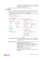
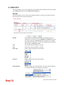
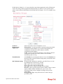
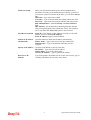
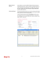
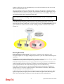
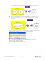
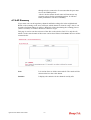
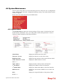
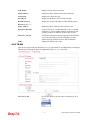
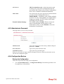
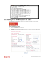
1
i
Vigor2710e/ne Series User’s Guide
Vigor2710e/ne Series User’s Guide
ii
Vigor2710e/ne Series
ADSL2/2+ Router
User’s Guide
Version: 1.0
Date: 01/12/2009
iii
Vigor2710e/ne Series User’s Guide
Copyright Information
Copyright
Declarations
Copyright 2009 All rights reserved. This publication contains information that is
protected by copyright. No part may be reproduced, transmitted, transcribed, stored in a
retrieval system, or translated into any language without written permission from the
copyright holders.
Trademarks
The following trademarks are used in this document:
z
Microsoft is a registered trademark of Microsoft Corp.
z
Windows, Windows 95, 98, Me, NT, 2000, XP, Vista and Explorer are
trademarks of Microsoft Corp.
z
Apple and Mac OS are registered trademarks of Apple Inc.
z
Other products may be trademarks or registered trademarks of their respective
manufacturers.
Safety Instructions and Approval
Safety
Instructions
Warranty
z
z
Read the installation guide thoroughly before you set up the router.
The router is a complicated electronic unit that may be repaired only be
authorized and qualified personnel. Do not try to open or repair the router
yourself.
z
Do not place the router in a damp or humid place, e.g. a bathroom.
z
The router should be used in a sheltered area, within a temperature range of +5 to
+40 Celsius.
z
Do not expose the router to direct sunlight or other heat sources. The housing and
electronic components may be damaged by direct sunlight or heat sources.
z
Do not deploy the cable for LAN connection outdoor to prevent electronic shock
hazards.
z
Keep the package out of reach of children.
z
When you want to dispose of the router, please follow local regulations on
conservation of the environment.
We warrant to the original end user (purchaser) that the router will be free from any
defects in workmanship or materials for a period of two (2) years from the date of
purchase from the dealer. Please keep your purchase receipt in a safe place as it serves
as proof of date of purchase. During the warranty period, and upon proof of purchase,
should the product have indications of failure due to faulty workmanship and/or
materials, we will, at our discretion, repair or replace the defective products or
components, without charge for either parts or labor, to whatever extent we deem
necessary tore-store the product to proper operating condition. Any replacement will
consist of a new or re-manufactured functionally equivalent product of equal value, and
will be offered solely at our discretion. This warranty will not apply if the product is
modified, misused, tampered with, damaged by an act of God, or subjected to abnormal
working conditions. The warranty does not cover the bundled or licensed software of
other vendors. Defects which do not significantly affect the usability of the product will
not be covered by the warranty. We reserve the right to revise the manual and online
documentation and to make changes from time to time in the contents hereof without
obligation to notify any person of such revision or changes.
Be a Registered
Owner
Web registration is preferred. You can register your Vigor router via
http://www.draytek.com.
Firmware & Tools
Updates
Due to the continuous evolution of DrayTek technology, all routers will be regularly
upgraded. Please consult the DrayTek web site for more information on newest
firmware, tools and documents.
http://www.draytek.com
Vigor2710e/ne Series User’s Guide
iv
European Community Declarations
Manufacturer:
Address:
Product:
DrayTek Corp.
No. 26, Fu Shing Road, HuKou Township, HsinChu Industrial Park, Hsin-Chu, Taiwan 303
Vigor2710e/ne Series Router
DrayTek Corp. declares that Vigor2710e/ne Series of routers are in compliance with the following essential
requirements and other relevant provisions of R&TTE Directive 1999/5/EEC.
The product conforms to the requirements of Electro-Magnetic Compatibility (EMC) Directive 2004/108/EC by
complying with the requirements set forth in EN55022/Class B and EN55024/Class B.
The product conforms to the requirements of Low Voltage (LVD) Directive 2006/95/EC by complying with the
requirements set forth in EN60950-1.
Regulatory Information
Federal Communication Commission Interference Statement
This equipment has been tested and found to comply with the limits for a Class B digital device, pursuant to Part
15 of the FCC Rules. These limits are designed to provide reasonable protection against harmful interference in a
residential installation. This equipment generates, uses and can radiate radio frequency energy and, if not installed
and used in accordance with the instructions, may cause harmful interference to radio communications. However,
there is no guarantee that interference will not occur in a particular installation. If this equipment does cause
harmful interference to radio or television reception, which can be determined by turning the equipment off and
on, the user is encouraged to try to correct the interference by one of the following measures:
z
Reorient or relocate the receiving antenna.
z
Increase the separation between the equipment and receiver.
z
Connect the equipment into an outlet on a circuit different from that to which the receiver is connected.
z
Consult the dealer or an experienced radio/TV technician for help.
This device complies with Part 15 of the FCC Rules. Operation is subject to the following two conditions:
(1) This device may not cause harmful interference, and
(2) This device may accept any interference received, including interference that may cause undesired operation.
Please visit http://www.draytek.com/user/AboutRegulatory.php
This product is designed for DSL, POTS and 2.4GHz WLAN network throughout the EC region and Switzerland
with restrictions in France. Please see the user manual for the applicable networks on your product.
v
Vigor2710e/ne Series User’s Guide
Vigor2710e/ne Series User’s Guide
vi
Table of Contents
1
Preface ...............................................................................................................1
1.1 Web Configuration Buttons Explanation ................................................................................. 1
1.2 LED Indicators and Connectors .............................................................................................. 2
1.2.1 For Vigor2710e ................................................................................................................. 2
1.2.2 For Vigor2710ne ............................................................................................................... 3
1.3 Hardware Installation .............................................................................................................. 4
2
Configuring Basic Settings ..............................................................................5
2.1 Two-Level Management.......................................................................................................... 5
2.2 Accessing Web Page .............................................................................................................. 5
2.3 Changing Password ................................................................................................................ 6
2.4 Quick Start Wizard .................................................................................................................. 8
2.4.1 Adjusting Protocol/Encapsulation ..................................................................................... 9
2.4.2 PPPoE/PPPoA................................................................................................................ 10
2.4.3 1483 Bridged IP .............................................................................................................. 11
2.4.4 1483 Routed IP............................................................................................................... 12
2.5 Online Status......................................................................................................................... 13
2.6 Saving Configuration............................................................................................................. 14
3
User Mode Operation............................................................................................15
3.1 Internet Access...................................................................................................................... 15
3.1.1 Basics of Internet Protocol (IP) Network......................................................................... 15
3.1.2 PPPoE/PPPoA................................................................................................................ 16
3.1.3 MPoA .............................................................................................................................. 19
3.2 LAN ....................................................................................................................................... 21
3.2.1 Basics of LAN ................................................................................................................. 21
3.2.2 General Setup................................................................................................................. 22
3.3 NAT ....................................................................................................................................... 24
3.3.1 Port Redirection .............................................................................................................. 24
3.3.2 DMZ Host........................................................................................................................ 27
3.3.3 Open Ports...................................................................................................................... 29
3.4 Applications ........................................................................................................................... 30
3.4.1 Dynamic DNS ................................................................................................................. 30
3.4.2 UPnP............................................................................................................................... 32
3.5 Wireless LAN ........................................................................................................................ 34
3.5.1 Basic Concepts............................................................................................................... 34
3.5.2 General Setup................................................................................................................. 36
vii
Vigor2710e/ne Series User’s Guide
3.5.3 Security ........................................................................................................................... 39
3.5.4 Access Control................................................................................................................ 40
3.5.5 Station List ...................................................................................................................... 41
3.6 System Maintenance............................................................................................................. 42
3.6.1 System Status................................................................................................................. 42
3.6.2 User Password ............................................................................................................... 43
3.6.3 Time and Date ................................................................................................................ 44
3.6.4 Reboot System ............................................................................................................... 44
3.7 Diagnostics............................................................................................................................ 45
3.7.1 DHCP Table.................................................................................................................... 45
3.7.2 Ping Diagnosis................................................................................................................ 46
3.7.3 Trace Route .................................................................................................................... 46
3.8 Support Area ......................................................................................................................... 47
4
Admin Mode Operation.........................................................................................49
4.1 Internet Access...................................................................................................................... 49
4.1.1 Basics of Internet Protocol (IP) Network......................................................................... 49
4.1.2 PPPoE/PPPoA................................................................................................................ 50
4.1.3 MPoA .............................................................................................................................. 53
4.1.4 Multi-PVCs...................................................................................................................... 55
4.2 LAN ....................................................................................................................................... 60
4.2.1 Basics of LAN ................................................................................................................. 60
4.2.2 General Setup................................................................................................................. 62
4.2.3 Static Route .................................................................................................................... 63
4.3 NAT ....................................................................................................................................... 66
4.3.1 Port Redirection .............................................................................................................. 66
4.3.2 DMZ Host........................................................................................................................ 69
4.3.3 Open Ports...................................................................................................................... 71
4.4 Firewall .................................................................................................................................. 73
4.4.1 Basics for Firewall........................................................................................................... 73
4.4.2 General Setup................................................................................................................. 75
4.4.3 Filter Setup ..................................................................................................................... 76
4.4.4 DoS Defense .................................................................................................................. 81
4.4.5 URL Content Filter .......................................................................................................... 84
4.5 Objects Settings .................................................................................................................... 87
4.5.1 IP Object ......................................................................................................................... 87
4.5.2 IP Group ......................................................................................................................... 89
4.5.3 Service Type Object ....................................................................................................... 90
4.5.4 Service Type Group........................................................................................................ 91
4.6 Applications ........................................................................................................................... 92
4.6.1 Dynamic DNS ................................................................................................................. 92
4.6.2 Schedule ......................................................................................................................... 94
4.6.3 UPnP............................................................................................................................... 96
4.6.4 IGMP............................................................................................................................... 98
4.7 Wireless LAN ........................................................................................................................ 98
4.7.1 Basic Concepts............................................................................................................... 98
4.7.2 General Setup............................................................................................................... 100
Vigor2710e/ne Series User’s Guide
viii
4.7.3 Security ......................................................................................................................... 103
4.7.4 Access Control.............................................................................................................. 104
4.7.5 WPS.............................................................................................................................. 105
4.7.6 Advanced Setting.......................................................................................................... 107
4.7.7 WMM Configuration ...................................................................................................... 108
4.7.8 AP Discovery ................................................................................................................ 110
4.7.9 Station List .................................................................................................................... 111
4.8 System Maintenance............................................................................................................112
4.8.1 System Status............................................................................................................... 112
4.8.2 TR-069 .......................................................................................................................... 113
4.8.3 Administrator Password................................................................................................ 114
4.8.4 Configuration Backup ................................................................................................... 114
4.8.5 Syslog/Mail Alert ........................................................................................................... 116
4.8.6 Time and Date .............................................................................................................. 118
4.8.7 Management................................................................................................................. 119
4.8.8 Reboot System ............................................................................................................. 120
4.8.9 Firmware Upgrade ........................................................................................................ 120
4.9 Diagnostics.......................................................................................................................... 121
4.9.1 Dial-out Trigger ............................................................................................................. 121
4.9.2 Routing Table ............................................................................................................... 122
4.9.3 ARP Cache Table ......................................................................................................... 122
4.9.4 DHCP Table.................................................................................................................. 123
4.9.5 NAT Sessions Table ..................................................................................................... 123
4.9.6 Ping Diagnosis.............................................................................................................. 124
4.9.7 Trace Route .................................................................................................................. 125
4.10 Support Area ..................................................................................................................... 125
5
Trouble Shooting ...........................................................................................127
5.1 Checking If the Hardware Status Is OK or Not.................................................................... 127
5.2 Checking If the Network Connection Settings on Your Computer Is OK or Not ................. 128
5.3 Pinging the Router from Your Computer ............................................................................. 130
5.4 Checking If the ISP Settings are OK or Not ........................................................................ 131
5.5 Backing to Factory Default Setting If Necessary ................................................................ 132
5.6 Contacting Your Dealer ....................................................................................................... 133
ix
Vigor2710e/ne Series User’s Guide
1
Preface
Vigor2710e series is an ADSL router. It integrates IP layer QoS, NAT session/bandwidth
management to help users control works well with large bandwidth.
The object-based design used in SPI (Stateful Packet Inspection) firewall allows users to set
firewall policy with ease. By the way, DoS/DDoS prevention strengthens the security outside
and control inside.
Object-based firewall is flexible and allows your network be safe. Vigor2710e series
provides two-level management to simplify the configuration of network connection. The
user operation allows user accessing into WEB interface via simple configuration. However,
if users want to have advanced configurations, they can access into WEB interface through
administration operation.
1.1 Web Configuration Buttons Explanation
Several main buttons appeared on the web pages are defined as the following:
Save and apply current settings.
Cancel current settings and recover to the previous saved settings.
Clear all the selections and parameters settings, including selection from
drop-down list. All the values must be reset with factory default settings.
Add new settings for specified item.
Edit the settings for the selected item.
Delete the selected item with the corresponding settings.
Note: For the other buttons shown on the web pages, please refer to Chapter 4 for detailed
explanation.
1
Vigor2710e/ne Series User’s Guide
1.2 LED Indicators and Connectors
Before you use the Vigor router, please get acquainted with the LED indicators and
connectors first.
1.2.1 For Vigor2710e
LED
ACT
(Activity)
DSL
Status
Blinking
Off
On
Blinking
LAN
1/2/3/4
CSM
Interface
DSL
LAN (1-4)
On
Off
Blinking
On
Explanation
The router is powered on and running
normally.
The router is powered off.
The router is ready to access Internet
through DSL link.
Slowly: The modem is ready.
Quickly: The connection is training.
The port is connected.
The port is disconnected.
The data is transmitting.
The profile(s) of URL/Web Content
Filter application can be enabled from
Firewall >>URL Content Filter.
Description
Connecter for accessing the Internet through
ADSL2/2+.
Connecters for local networked devices.
Restore the default settings. Usage: Turn on the
router. Press the button and keep for more than 10
seconds. Then the router will restart with the
factory default configuration.
ON/OFF: Power switch.
PWR: Connecter for a power adapter.
Vigor2710e/ne Series User’s Guide
2
1.2.2 For Vigor2710ne
LED
Status
Explanation
ACT
(Activity)
Blinking
The router is powered on and running
normally.
The router is powered off.
The router is ready to access Internet
through DSL link.
Slowly: The modem is ready.
Quickly: The connection is training.
The port is connected.
The port is disconnected.
The data is transmitting.
Wireless access point is ready.
It will blink while wireless traffic goes
through.
The WPS is on.
The WPS is off.
Waiting for wireless client sending requests
for connection about two minutes.
Press this button for 2 seconds to wait for
client device making network connection
through WPS. When the LED lights up, the
WPS will be on.
The WPS is off.
Waiting for wireless client sending requests
for connection about 2 minutes.
DSL
Off
On
Blinking
LAN 1/2/3/4
WLAN
On
Off
Blinking
On
Blinking
WPS
On
Off
Blinking
WPS Button
On
Off
Blinking
Interface
Description
WLAN
Press the button once to enable (WLAN LED on) or
disable (WLAN LED off) wireless connection.
DSL
LAN (1-4)
Connecter for accessing the Internet through ADSL2/2+.
Connecters for local networked devices.
Restore the default settings. Usage: Turn on the
router. Press the button and keep for more than
10 seconds. Then the router will restart with the
factory default configuration.
ON/OFF: Power switch.
PWR: Connecter for a power adapter.
3
Vigor2710e/ne Series User’s Guide
1.3 Hardware Installation
Before starting to configure the router, you have to connect your devices correctly.
1.
Connect the ADSL interface to the external ADSL splitter with an ADSL line cable for
all models.
2.
Connect one end of an Ethernet cable (RJ-45) to one of the LAN ports of the router and
the other end of the cable (RJ-45) into the Ethernet port on your computer.
3.
Connect one end of the power adapter to the router’s power port on the rear panel, and
the other side into a wall outlet.
4.
Power on the device by pressing down the power switch on the rear panel.
5.
The system starts to initiate. After completing the system test, the ACT LED will light
up and start blinking.
Here, we take Annex A model as an example for describing hardware installation.
Vigor2710e/ne Series User’s Guide
4
2
Configuring Basic Settings
For using the router properly, it is necessary for you to change the password of web
configuration for security and adjust primary basic settings.
2.1 Two-Level Management
This chapter explains how to setup a password for an administrator/user and how to adjust
basic/advanced settings for accessing Internet successfully.
For user mode operation, do not type any word on the window and click Login for the
simple web pages for configuration. Yet, for admin mode operation, please type
“admin/admin” on Username/Password and click Login for full configuration.
2.2 Accessing Web Page
1.
Make sure your PC connects to the router correctly.
Notice: You may either simply set up your computer to get IP dynamically
from the router or set up the IP address of the computer to be the same subnet as
the default IP address of Vigor router 192.168.1.1. For the detailed
information, please refer to the later section - Trouble Shooting of the guide.
2.
Open a web browser on your PC and type http://192.168.1.1. The following window
will be open to ask for username and password.
3.
For user’s operation, do not type any word on the window and click Login for the
simple web pages for configuration. Yet, for administrator’s operation, please type
“admin/admin” on Username/Password and click Login for full configuration.
Notice: If you fail to access to the web configuration, please go to “Trouble
Shooting” for detecting and solving your problem.
4.
The web page can be logged out according to the chosen condition. The default setting
is Auto Logout, which means the web configuration system will logout after 5 minutes
without any operation. Change the setting for your necessity.
5
Vigor2710e/ne Series User’s Guide
2.3 Changing Password
No matter user mode operation or admin mode operation, please change the password for the
original security of the router.
1.
Open a web browser on your PC and type http://192.168.1.1. A pop-up window will
open to ask for username and password.
2.
Please type “admin/admin” on Username/Password for administration operation.
Otherwise, do not type any word (both username and password are Null for user
operation) on the window and click Login on the window.
3.
Now, the Main Screen will appear.
Main screen for admin mode operation (full configuration)
Vigor2710e/ne Series User’s Guide
6
Main screen for user mode operation (simple configuration)
Note: The home page will change slightly in accordance with the type of the router you
have.
4. Go to System Maintenance page and choose Administrator Password/User
Password.
or
5.
Enter the login password (the default is blank) on the field of Old Password. Type the
new password in New Password and Confirm Password fields. Then click OK to
continue.
6.
Now, the password has been changed. Next time, use the new password to access the
Web Configurator for this router.
7
Vigor2710e/ne Series User’s Guide
2.4 Quick Start Wizard
Notice: Quick Start Wizard for user operation is the same as for administrator’s
operation.
If your router can be under an environment with high speed NAT, the configuration provide
here can help you to deploy and use the router quickly. The first screen of Quick Start
Wizard is entering login password. After typing the password, please click Next.
In the Quick Start Wizard, you can configure the router to access the Internet with different
protocol/modes such as PPPoE, PPPoA, Bridged IP, or Routed IP. The router supports the
Vigor2710e/ne Series User’s Guide
8
2.4.1 Adjusting Protocol/Encapsulation
In the Quick Start Wizard, you can configure the router to access the Internet with different
protocol/modes such as PPPoE, PPPoA, Bridged IP, or Routed IP. The router supports the
ADSL WAN interface for Internet access.
Now, you have to select an appropriate WAN connection type for connecting to the Internet
through this router according to the settings that your ISP provided.
VPI
Stands for Virtual Path Identifier. It is an 8-bit header inside
each ATM cell that indicates where the cell should be routed. The
ATM, is a method of sending data in small packets of fixed sizes.
It is used for transferring data to client computers.
VCI
Stands for Virtual Channel Identifier. It is a 16-bit field inside
ATM cell’s header that indicates the cell’s next destination as it
travels through the network. A virtual channel is a logical
connection between two end devices on the network.
Protocol/Encapsulation
Select an IP mode for this WAN interface. There are several
available modes for Internet access such as PPPoE, PPPoA,
Bridged IP and Routed IP.
Fixed IP
Click Yes to specify a fixed IP for the router. Otherwise, click No
(Dynamic IP) to allow the router choosing a dynamic IP. If you
choose No, the following IP Address, Subnet Mask and Default
Gateway will not be changed.
IP Address
Assign an IP address for the protocol that you select.
9
Vigor2710e/ne Series User’s Guide
Subnet Mask
Assign a subnet mask value for the protocol of Routed IP and
Bridged IP.
Default Gateway
Assign an IP address to the gateway for the protocol of Routed
IP and Bridged IP.
Primary DNS
Assign an IP address to the primary DNS.
Second DNS
Assign an IP address to the secondary DNS.
2.4.2 PPPoE/PPPoA
PPPoE stands for Point-to-Point Protocol over Ethernet. It relies on two widely accepted
standards: PPP and Ethernet. It connects users through an Ethernet to the Internet with a
common broadband medium, such as a single DSL line, wireless device or cable modem. All
the users over the Ethernet can share a common connection.
PPPoE is used for most of DSL modem users. All local users can share one PPPoE
connection for accessing the Internet. Your service provider will provide you information
about user name, password, and authentication mode.
If your ISP provides you the PPPoE connection, please select PPPoE for this router. The
following page will be shown:
User Name
Assign a specific valid user name provided by the ISP.
Password
Assign a valid password provided by the ISP.
Confirm Password
Retype the password.
Vigor2710e/ne Series User’s Guide
10
Click Next for viewing summary of such connection.
Click Finish. Then, the system status of this protocol will be shown.
2.4.3 1483 Bridged IP
Click 1483 Bridged IP as the protocol. Type in all the information that your ISP provides
for this protocol.
11
Vigor2710e/ne Series User’s Guide
Click Next for viewing summary of such connection.
Click Finish. Then, the system status of this protocol will be shown.
2.4.4 1483 Routed IP
Click 1483 Routed IP as the protocol. Type in all the information that your ISP provides for
this protocol.
Vigor2710e/ne Series User’s Guide
12
After finishing the settings in this page, click Next to see the following page.
Click Finish. Then, the system status of this protocol will be shown.
2.5 Online Status
The online status shows the system status, WAN status, ADSL Information and other status
related to this router within one page. If you select PPPoE/PPPoA as the protocol, you will
find out a link of Dial PPPoE or Drop PPPoE in the Online Status web page.
Online status for PPPoE
Detailed explanation is shown below:
Primary DNS
Displays the IP address of the primary DNS.
Secondary DNS
Displays the IP address of the secondary DNS.
LAN Status
IP Address
Displays the IP address of the LAN interface.
13
Vigor2710e/ne Series User’s Guide
TX Packets
Displays the total transmitted packets at the LAN interface.
RX Packets
Displays the total number of received packets at the LAN interface.
WAN1 Status
Line
Displays the physical connection (Ethernet) of this interface.
Name
Displays the name set in WAN1/WAN web page.
Mode
Displays the type of WAN connection (e.g., PPPoE).
Up Time
Displays the total uptime of the interface.
IP
Displays the IP address of the WAN interface.
GW IP
Displays the IP address of the default gateway.
TX Packets
Displays the total transmitted packets at the WAN interface.
TX Rate
Displays the speed of transmitted octets at the WAN interface.
RX Packets
Displays the total number of received packets at the WAN
interface.
RX Rate
Displays the speed of received octets at the WAN interface.
Note: The words in green mean that the WAN connection of that interface is ready for
accessing Internet; the words in red mean that the WAN connection of that interface is not
ready for accessing Internet.
2.6 Saving Configuration
Each time you click OK on the web page for saving the configuration, you can find
messages showing the system interaction with you.
Ready indicates the system is ready for you to input settings.
Settings Saved means your settings are saved once you click Finish or OK button.
Vigor2710e/ne Series User’s Guide
14
3
User Mode Operation
This chapter will guide users to execute simple configuration through user mode operation.
1.
Open a web browser on your PC and type http://192.168.1.1. The window will ask for
typing username and password.
2.
Do not type any word (both username and password are Null for user operation) on the
window and click Login on the window.
Now, the Main Screen will appear. Be aware that “User mode” will be displayed on the
bottom left side.
3.1 Internet Access
Quick Start Wizard offers user an easy method to quick setup the connection mode for the
router. Moreover, if you want to adjust more settings for different WAN modes, please go to
WAN group and click the Internet Access link.
3.1.1 Basics of Internet Protocol (IP) Network
IP means Internet Protocol. Every device in an IP-based Network including routers, print
server, and host PCs, needs an IP address to identify its location on the network. To avoid
address conflicts, IP addresses are publicly registered with the Network Information Centre
(NIC). Having a unique IP address is mandatory for those devices participated in the public
network but not in the private TCP/IP local area networks (LANs), such as host PCs under
the management of a router since they do not need to be accessed by the public. Hence, the
NIC has reserved certain addresses that will never be registered publicly. These are known as
private IP addresses, and are listed in the following ranges:
From 10.0.0.0 to 10.255.255.255
From 172.16.0.0 to 172.31.255.255
From 192.168.0.0 to 192.168.255.255
15
Vigor2710e/ne Series User’s Guide
What are Public IP Address and Private IP Address
As the router plays a role to manage and further protect its LAN, it interconnects groups of
host PCs. Each of them has a private IP address assigned by the built-in DHCP server of the
Vigor router. The router itself will also use the default private IP address: 192.168.1.1 to
communicate with the local hosts. Meanwhile, Vigor router will communicate with other
network devices through a public IP address. When the data flow passing through, the
Network Address Translation (NAT) function of the router will dedicate to translate
public/private addresses, and the packets will be delivered to the correct host PC in the local
area network. Thus, all the host PCs can share a common Internet connection.
Get Your Public IP Address from ISP
In ADSL deployment, the PPP (Point to Point)-style authentication and authorization is
required for bridging customer premises equipment (CPE). Point to Point Protocol over
Ethernet (PPPoE) connects a network of hosts via an access device to a remote access
concentrator or aggregation concentrator. This implementation provides users with
significant ease of use. Meanwhile it provides access control, billing, and type of service
according to user requirement.
When a router begins to connect to your ISP, a serial of discovery process will occur to ask
for a connection. Then a session will be created. Your user ID and password is authenticated
via PAP or CHAP with RADIUS authentication system. And your IP address, DNS server,
and other related information will usually be assigned by your ISP.
Below shows the menu items for Internet Access.
3.1.2 PPPoE/PPPoA
PPPoA, included in RFC1483, can be operated in either Logical Link Control-Subnetwork
Access Protocol or VC-Mux mode. As a CPE device, Vigor router encapsulates the PPP
session based for transport across the ADSL loop and your ISP’s Digital Subscriber Line
Access Multiplexer (SDLAM).
To choose PPPoE or PPPoA as the accessing protocol of the internet, please select
PPPoE/PPPoA from the Internet Access menu. The following web page will be shown.
Vigor2710e/ne Series User’s Guide
16
Enable/Disable
Click Enable for activating this function. If you click Disable, this
function will be closed and all the settings that you adjusted in this
page will be invalid.
DSL Modem Settings
Set up the DSL parameters required by your ISP. These are vital
for building DSL connection to your ISP.
Multi-PVC channel - The selections displayed here are
determined by the page of Internet Access – Multi PVCs. Select
M-PVCs Channel means no selection will be chosen.
VPI - Type in the value provided by ISP.
VCI - Type in the value provided by ISP.
Encapsulating Type - Drop down the list to choose the type
provided by ISP.
Protocol - Drop down the list to choose the one provided by ISP.
If you have already used Quick Start Wizard to set the protocol,
then it is not necessary for you to change any settings in this group.
Modulation – Drop down the list to choose a proper modulation
for the router.
PPPoE Pass-through
The router offers PPPoE dial-up connection. Besides, you also can
establish the PPPoE connection directly from local clients to your
ISP via the Vigor router. When PPPoA protocol is selected, the
PPPoE package transmitted by PC will be transformed into PPPoA
package and sent to WAN server. Thus, the PC can access Internet
through such direction.
For Wired LAN – If you check this box, PCs on the same network
can use another set of PPPoE session (different with the Host PC)
to access into Internet.
For Wireless LAN – If you check this box, PCs on the same
17
Vigor2710e/ne Series User’s Guide
wireless network can use another set of PPPoE session (different
with the Host PC) to access into Internet.
ISP Access Setup
Enter your allocated username, password and authentication
parameters according to the information provided by your ISP. If
you want to connect to Internet all the time, you can check Always
On.
Username – Type in the username provided by ISP in this field.
Password – Type in the password provided by ISP in this field.
PPP Authentication – Select PAP only or PAP or CHAP for
PPP.
Idle Timeout – Set the timeout for breaking down the Internet
after passing through the time without any action. This setting is
active only when the Active on demand option for Active Mode is
selected in WAN>> General Setup page.
IP Address From ISP
Usually ISP dynamically assigns IP address to you each time you
connect to it and request. In some case, your ISP provides service
to always assign you the same IP address whenever you request.
In this case, you can fill in this IP address in the Fixed IP field.
Please contact your ISP before you want to use this function.
WAN IP Alias - If you have multiple public IP addresses and
would like to utilize them on the WAN interface, please use
WAN IP Alias. You can set up to 8 public IP addresses other than
the current one you are using. Notice that this setting is available
for WAN1 only. Type the additional WAN IP address and check
the Enable box. Then click OK to exit the dialog.
Fixed IP – Click Yes to use this function and type in a fixed IP
address in the box of Fixed IP Address.
Default MAC Address – You can use Default MAC Address or
specify another MAC address by typing on the boxes of MAC
Address for the router.
Specify a MAC Address – Type the MAC address for the router
manually.
After finishing all the settings here, please click OK to activate them.
Vigor2710e/ne Series User’s Guide
18
3.1.3 MPoA
MPoA is a specification that enables ATM services to be integrated with existing LANs,
which use either Ethernet, or TCP/IP protocols. The goal of MPoA is to allow different
LANs to send packets to each other via an ATM backbone.
To use MPoA as the accessing protocol of the Internet, select MPoA mode. The following
web page will appear.
MPoA (RFC1483/2684) Click Enable for activating this function. If you click Disable, this
function will be closed and all the settings that you adjusted in this
page will be invalid.
DSL Modem Settings
Set up the DSL parameters required by your ISP. These are vital
for building DSL connection to your ISP.
Multi-PVC channel - The selections displayed here are
determined by the page of Internet Access – Multi PVCs. Select
M-PVCs Channel means no selection will be chosen.
Encapsulating Type - Drop down the list to choose the type
provided by ISP.
VPI - Type in the value provided by ISP.
VCI - Type in the value provided by ISP.
Modulation – Drop down the list to choose a proper modulation
for the router.
RIP Protocol
Routing Information Protocol is abbreviated as RIP(RFC1058)
specifying how routers exchange routing tables information. Click
Enable RIP for activating this function.
Bridge Mode
If you choose Bridged IP as the protocol, you can check this box
to invoke the function. The router will work as a bridge modem.
WAN IP Network
This group allows you to obtain an IP address automatically and
19
Vigor2710e/ne Series User’s Guide
Settings
allows you type in IP address manually.
Obtain an IP address automatically – Click this button to obtain
the IP address automatically.
Router Name – Type in the router name provided by ISP.
Domain Name – Type in the domain name that you have assigned.
Specify an IP address – Click this radio button to specify some
data.
WAN IP Alias - If you have multiple public IP addresses and
would like to utilize them on the WAN interface, please use WAN
IP Alias. You can set up to 8 public IP addresses other than the
current one you are using. Notice that this setting is available for
WAN1 only. Type the additional WAN IP address and check the
Enable box. Then click OK to exit the dialog.
IP Address – Type in the private IP address.
Subnet Mask – Type in the subnet mask.
Gateway IP Address – Type in gateway IP address.
Default MAC Address Type in MAC address for the router. You
can use Default MAC Address or specify another MAC address
for your necessity.
MAC Address – Type in the MAC address for the router
manually.
DNS Server IP
Address
Vigor2710e/ne Series User’s Guide
Type in the primary IP address for the router. If necessary, type in
secondary IP address for necessity in the future.
20
3.2 LAN
Local Area Network (LAN) is a group of subnets regulated and ruled by router. The design
of network structure is related to what type of public IP addresses coming from your ISP.
3.2.1 Basics of LAN
The most generic function of Vigor router is NAT. It creates a private subnet of your own. As
mentioned previously, the router will talk to other public hosts on the Internet by using
public IP address and talking to local hosts by using its private IP address. What NAT does is
to translate the packets from public IP address to private IP address to forward the right
packets to the right host and vice versa. Besides, Vigor router has a built-in DHCP server that
assigns private IP address to each local host. See the following diagram for a briefly
understanding.
In some special case, you may have a public IP subnet from your ISP such as
220.135.240.0/24. This means that you can set up a public subnet or call second subnet that
each host is equipped with a public IP address. As a part of the public subnet, the Vigor
router will serve for IP routing to help hosts in the public subnet to communicate with other
public hosts or servers outside. Therefore, the router should be set as the gateway for public
hosts.
21
Vigor2710e/ne Series User’s Guide
What is Routing Information Protocol (RIP)
Vigor router will exchange routing information with neighboring routers using the RIP to
accomplish IP routing. This allows users to change the information of the router such as IP
address and the routers will automatically inform for each other.
3.2.2 General Setup
This page provides you the general settings for LAN.
Click LAN to open the LAN settings page and choose General Setup.
IP Address
Type in private IP address for connecting to a local private network
(Default: 192.168.1.1).
Subnet Mask
Type in an address code that determines the size of the network.
(Default: 255.255.255.0/ 24)
DHCP Server
Configuration
DHCP stands for Dynamic Host Configuration Protocol. The
router by factory default acts a DHCP server for your network so
Vigor2710e/ne Series User’s Guide
22
it automatically dispatch related IP settings to any local user
configured as a DHCP client. It is highly recommended that you
leave the router enabled as a DHCP server if you do not have a
DHCP server for your network.
If you want to use another DHCP server in the network other than
the Vigor Router’s, you can let Relay Agent help you to redirect the
DHCP request to the specified location.
Enable Server - Let the router assign IP address to every host in
the LAN.
Disable Server – Let you manually assign IP address to every host
in the LAN.
Start IP Address - Enter a value of the IP address pool for the
DHCP server to start with when issuing IP addresses. If the 1st IP
address of your router is 192.168.1.1, the starting IP address must
be 192.168.1.2 or greater, but smaller than 192.168.1.254.
IP Pool Counts - Enter the maximum number of PCs that you
want the DHCP server to assign IP addresses to. The default is 50
and the maximum is 253.
Gateway IP Address - Enter a value of the gateway IP address for
the DHCP server. The value is usually as same as the 1st IP address
of the router, which means the router is the default gateway.
DNS Server
Configuration
DNS stands for Domain Name System. Every Internet host must
have a unique IP address, also they may have a human-friendly,
easy to remember name such as www.yahoo.com. The DNS
server converts the user-friendly name into its equivalent IP
address.
Primary IP Address -You must specify a DNS server IP address
here because your ISP should provide you with usually more than
one DNS Server. If your ISP does not provide it, the router will
automatically apply default DNS Server IP address: 194.109.6.66
to this field.
Secondary IP Address - You can specify secondary DNS server IP
address here because your ISP often provides you more than one
DNS Server. If your ISP does not provide it, the router will
automatically apply default secondary DNS Server IP address:
194.98.0.1 to this field.
The default DNS Server IP address can be found via Online Status:
If both the Primary IP and Secondary IP Address fields are left
empty, the router will assign its own IP address to local users as a
DNS proxy server and maintain a DNS cache.
If the IP address of a domain name is already in the DNS cache, the
router will resolve the domain name immediately. Otherwise, the
router forwards the DNS query packet to the external DNS server
by establishing a WAN (e.g. DSL/Cable) connection.
There are two common scenarios of LAN settings that stated in Chapter 4. For the
configuration examples, please refer to that chapter to get more information for your
necessity.
23
Vigor2710e/ne Series User’s Guide
3.3 NAT
Usually, the router serves as an NAT (Network Address Translation) router. NAT is a
mechanism that one or more private IP addresses can be mapped into a single public one.
Public IP address is usually assigned by your ISP, for which you may get charged. Private IP
addresses are recognized only among internal hosts.
When the outgoing packets destined to some public server on the Internet reach the NAT
router, the router will change its source address into the public IP address of the router, select
the available public port, and then forward it. At the same time, the router shall list an entry
in a table to memorize this address/port-mapping relationship. When the public server
response, the incoming traffic, of course, is destined to the router’s public IP address and the
router will do the inversion based on its table. Therefore, the internal host can communicate
with external host smoothly.
The benefit of the NAT includes:
z
Save cost on applying public IP address and apply efficient usage of IP address.
NAT allows the internal IP addresses of local hosts to be translated into one public IP
address, thus you can have only one IP address on behalf of the entire internal hosts.
z
Enhance security of the internal network by obscuring the IP address. There are
many attacks aiming victims based on the IP address. Since the attacker cannot be
aware of any private IP addresses, the NAT function can protect the internal network.
On NAT page, you will see the private IP address defined in RFC-1918. Usually we use
the 192.168.1.0/24 subnet for the router. As stated before, the NAT facility can map one
or more IP addresses and/or service ports into different specified services. In other words,
the NAT function can be achieved by using port mapping methods.
Below shows the menu items for NAT.
3.3.1 Port Redirection
Port Redirection is usually set up for server related service inside the local network (LAN),
such as web servers, FTP servers, E-mail servers etc. Most of the case, you need a public IP
address for each server and this public IP address/domain name are recognized by all users.
Since the server is actually located inside the LAN, the network well protected by NAT of
the router, and identified by its private IP address/port, the goal of Port Redirection function
is to forward all access request with public IP address from external users to the mapping
private IP address/port of the server.
Vigor2710e/ne Series User’s Guide
24
The port redirection can only apply to incoming traffic.
To use this function, please go to NAT page and choose Port Redirection web page. The
Port Redirection Table provides 20 port-mapping entries for the internal hosts.
Press any number under Index to access into next page for configuring port redirection.
25
Vigor2710e/ne Series User’s Guide
Enable
Check this box to enable such port redirection setting.
Mode
Two options (Single and Range) are provided here for you to
choose. To set a range for the specific service, select Range. In
Range mode, if the public port (start port and end port) and the
starting IP of private IP had been entered, the system will calculate
and display the ending IP of private IP automatically.
Service Name
Enter the description of the specific network service.
Protocol
Select the transport layer protocol (TCP or UDP).
WAN IP
Select the WAN IP used for port redirection. There are eight WAN
IP alias that can be selected and used for port redirection. The
default setting is All which means all the incoming data from any
port will be redirected to specified range of IP address and port.
Public Port
Specify which port can be redirected to the specified Private IP
and Port of the internal host. If you choose Range as the port
redirection mode, you will see two boxes on this field. Simply type
the required number on the first box. The second one will be
assigned automatically later.
Private IP
Specify the private IP address of the internal host providing the
service. If you choose Range as the port redirection mode, you will
see two boxes on this field. Type a complete IP address in the first
box (as the starting point) and the fourth digits in the second box
(as the end point).
Private Port
Specify the private port number of the service offered by the
internal host.
Active
Check this box to activate the port-mapping entry you have
defined.
Note that the router has its own built-in services (servers) such as Telnet, HTTP and FTP etc.
Since the common port numbers of these services (servers) are all the same, you may need to
reset the router in order to avoid confliction.
Vigor2710e/ne Series User’s Guide
26
3.3.2 DMZ Host
As mentioned above, Port Redirection can redirect incoming TCP/UDP or other traffic on
particular ports to the specific private IP address/port of host in the LAN. However, other IP
protocols, for example Protocols 50 (ESP) and 51 (AH), do not travel on a fixed port. Vigor
router provides a facility DMZ Host that maps ALL unsolicited data on any protocol to a
single host in the LAN. Regular web surfing and other such Internet activities from other
clients will continue to work without inappropriate interruption. DMZ Host allows a defined
internal user to be totally exposed to the Internet, which usually helps some special
applications such as Netmeeting or Internet Games etc.
The inherent security properties of NAT are somewhat bypassed if you set up DMZ host.
We suggest you to add additional filter rules or a secondary firewall.
Click DMZ Host to open the following page:
If you previously have set up WAN Alias for PPPoE/PPPoA or MPoA mode, you will find
them in Aux. WAN IP for your selection.
27
Vigor2710e/ne Series User’s Guide
Enable
Check to enable the DMZ Host function.
Private IP
Enter the private IP address of the DMZ host, or click Choose PC
to select one.
Choose PC
Click this button and then a window will automatically pop up, as
depicted below. The window consists of a list of private IP
addresses of all hosts in your LAN network. Select one private IP
address in the list to be the DMZ host.
When you have selected one private IP from the above dialog, the
IP address will be shown on the following screen. Click OK to
save the setting.
Vigor2710e/ne Series User’s Guide
28
3.3.3 Open Ports
Open Ports allows you to open a range of ports for the traffic of special applications.
Common application of Open Ports includes P2P application (e.g., BT, KaZaA, Gnutella,
WinMX, eMule and others), Internet Camera etc. Ensure that you keep the application
involved up-to-date to avoid falling victim to any security exploits.
Click Open Ports to open the following page:
Index
Indicate the relative number for the particular entry that you want to
offer service in a local host. You should click the appropriate index
number to edit or clear the corresponding entry.
Comment
Specify the name for the defined network service.
Local IP Address
Display the private IP address of the local host offering the service.
Status
Display the state for the corresponding entry. X or V is to represent
the Inactive or Active state.
To add or edit port settings, click one index number on the page. The index entry setup page
will pop up. In each index entry, you can specify 10 port ranges for diverse services.
29
Vigor2710e/ne Series User’s Guide
Enable Open Ports
Check to enable this entry.
Comment
Make a name for the defined network application/service.
WAN Interface
Specify the WAN interface that will be used for this entry.
Local Computer
Enter the private IP address of the local host or click Choose PC to
select one.
Choose PC
Click this button and, subsequently, a window having a list of
private IP addresses of local hosts will automatically pop up. Select
the appropriate IP address of the local host in the list.
Protocol
Specify the transport layer protocol. It could be TCP, UDP, or ----(none) for selection.
Start Port
Specify the starting port number of the service offered by the local
host.
End Port
Specify the ending port number of the service offered by the local
host.
3.4 Applications
Below shows the menu items for Applications.
3.4.1 Dynamic DNS
The ISP often provides you with a dynamic IP address when you connect to the Internet via
your ISP. It means that the public IP address assigned to your router changes each time you
access the Internet. The Dynamic DNS feature lets you assign a domain name to a dynamic
WAN IP address. It allows the router to update its online WAN IP address mappings on the
specified Dynamic DNS server. Once the router is online, you will be able to use the
registered domain name to access the router or internal virtual servers from the Internet. It is
particularly helpful if you host a web server, FTP server, or other server behind the router.
Vigor2710e/ne Series User’s Guide
30
Before you use the Dynamic DNS feature, you have to apply for free DDNS service to the
DDNS service providers. The router provides up to three accounts from three different
DDNS service providers. Basically, Vigor routers are compatible with the DDNS services
supplied by most popular DDNS service providers such as www.dyndns.org,
www.no-ip.com, www.dtdns.com, www.changeip.com, www.dynamic- nameserver.com.
You should visit their websites to register your own domain name for the router.
Enable the Function and Add a Dynamic DNS Account
1.
Assume you have a registered domain name from the DDNS provider, say
hostname.dyndns.org, and an account with username: test and password: test.
2.
In the DDNS setup menu, check Enable Dynamic DNS Setup.
Set to Factory Default
Clear all profiles and recover to factory settings.
Enable Dynamic DNS Setup Check this box to enable DDNS function.
3.
Index
Click the number below Index to access into the setting
page of DDNS setup to set account(s).
Domain Name
Display the domain name that you set on the setting page
of DDNS setup.
Active
Display if this account is active or inactive.
View Log
Display DDNS log status.
Force Update
Force the router updates its information to DDNS server.
Select Index number 1 to add an account for the router. Check Enable Dynamic DNS
Account, and choose correct Service Provider: dyndns.org, type the registered
hostname: hostname and domain name suffix: dyndns.org in the Domain Name block.
The following two blocks should be typed your account Login Name: test and
Password: test.
31
Vigor2710e/ne Series User’s Guide
4.
Enable Dynamic
DNS Account
Check this box to enable the current account. If you did
check the box, you will see a check mark appeared on the
Active column of the previous web page in step 2).
Service Provider
Select the service provider for the DDNS account.
Service Type
Select a service type (Dynamic, Custom or Static). If you
choose Custom, you can modify the domain that is chosen in
the Domain Name field.
Domain Name
Type in one domain name that you applied previously. Use
the drop down list to choose the desired domain.
Login Name
Type in the login name that you set for applying domain.
Password
Type in the password that you set for applying domain.
Click OK button to activate the settings. You will see your setting has been saved.
The Wildcard and Backup MX features are not supported for all Dynamic DNS providers.
You could get more detailed information from their websites.
Disable the Function and Clear all Dynamic DNS Accounts
In the DDNS setup menu, uncheck Enable Dynamic DNS Setup, and push Clear All button
to disable the function and clear all accounts from the router.
Delete a Dynamic DNS Account
In the DDNS setup menu, click the Index number you want to delete and then push Clear
All button to delete the account.
3.4.2 UPnP
The UPnP (Universal Plug and Play) protocol is supported to bring to network connected
devices the ease of installation and configuration which is already available for directly
connected PC peripherals with the existing Windows 'Plug and Play' system. For NAT
routers, the major feature of UPnP on the router is “NAT Traversal”. This enables
applications inside the firewall to automatically open the ports that they need to pass through
a router. It is more reliable than requiring a router to work out by itself which ports need to
be opened. Further, the user does not have to manually set up port mappings or a DMZ.
UPnP is available on Windows XP and the router provide the associated support for MSN
Messenger to allow full use of the voice, video and messaging features.
Vigor2710e/ne Series User’s Guide
32
Enable UPNP Service
Accordingly, you can enable either the Connection Control
Service or Connection Status Service.
After setting Enable UPNP Service setting, an icon of IP Broadband Connection on
Router on Windows XP/Network Connections will appear. The connection status and
control status will be able to be activated. The NAT Traversal of UPnP enables the
multimedia features of your applications to operate. This has to manually set up port
mappings or use other similar methods. The screenshots below show examples of this
facility.
The UPnP facility on the router enables UPnP aware applications such as MSN Messenger to
discover what are behind a NAT router. The application will also learn the external IP
address and configure port mappings on the router. Subsequently, such a facility forwards
packets from the external ports of the router to the internal ports used by the application.
33
Vigor2710e/ne Series User’s Guide
The reminder as regards concern about Firewall and UPnP
Can't work with Firewall Software
Enabling firewall applications on your PC may cause the UPnP function not working
properly. This is because these applications will block the accessing ability of some
network ports.
Security Considerations
Activating the UPnP function on your network may incur some security threats. You
should consider carefully these risks before activating the UPnP function.
¾ Some Microsoft operating systems have found out the UPnP weaknesses and hence
you need to ensure that you have applied the latest service packs and patches.
¾ Non-privileged users can control some router functions, including removing and
adding port mappings.
The UPnP function dynamically adds port mappings on behalf of some UPnP-aware
applications. When the applications terminate abnormally, these mappings may not be
removed.
3.5 Wireless LAN
This function is used for “ne” models.
3.5.1 Basic Concepts
Over recent years, the market for wireless communications has enjoyed tremendous growth.
Wireless technology now reaches or is capable of reaching virtually every location on the
surface of the earth. Hundreds of millions of people exchange information every day via
wireless communication products. The Vigor “ne” model, a.k.a. Vigor wireless router, is
designed for maximum flexibility and efficiency of a small office/home. Any authorized
staff can bring a built-in WLAN client PDA or notebook into a meeting room for conference
without laying a clot of LAN cable or drilling holes everywhere. Wireless LAN enables high
mobility so WLAN users can simultaneously access all LAN facilities just like on a wired
LAN as well as Internet access.
The Vigor wireless routers are equipped with a wireless LAN interface compliant with the
standard IEEE 802.11n protocol. To boost its performance further, the Vigor Router is also
loaded with advanced wireless technology to lift up data rate up to 150 Mbps*. Hence, you
can finally smoothly enjoy stream music and video.
Vigor2710e/ne Series User’s Guide
34
Note: * The actual data throughput will vary according to the network conditions and
environmental factors, including volume of network traffic, network overhead and
building materials.
In an Infrastructure Mode of wireless network, Vigor wireless router plays a role as an
Access Point (AP) connecting to lots of wireless clients or Stations (STA). All the STAs will
share the same Internet connection via Vigor wireless router. The General Settings will set
up the information of this wireless network, including its SSID as identification, located
channel etc.
Security Overview
Real-time Hardware Encryption: Vigor Router is equipped with a hardware AES
encryption engine so it can apply the highest protection to your data without influencing user
experience.
Complete Security Standard Selection: To ensure the security and privacy of your wireless
communication, we provide several prevailing standards on market.
WEP (Wired Equivalent Privacy) is a legacy method to encrypt each frame transmitted via
radio using either a 64-bit or 128-bit key. Usually access point will preset a set of four keys
and it will communicate with each station using only one out of the four keys.
WPA (Wi-Fi Protected Access), the most dominating security mechanism in industry, is
separated into two categories: WPA-personal or called WPA Pre-Share Key (WPA/PSK),
and WPA-Enterprise or called WPA/802.1x.
In WPA-Personal, a pre-defined key is used for encryption during data transmission. WPA
applies Temporal Key Integrity Protocol (TKIP) for data encryption while WPA2 applies
AES. The WPA-Enterprise combines not only encryption but also authentication.
Since WEP has been proved vulnerable, you may consider using WPA for the most secure
connection. You should select the appropriate security mechanism according to your needs.
No matter which security suite you select, they all will enhance the over-the-air data
protection and /or privacy on your wireless network. The Vigor wireless router is very
flexible and can support multiple secure connections with both WEP and WPA at the same
time.
Separate the Wireless and the Wired LAN- WLAN Isolation enables you to isolate your
wireless LAN from wired LAN for either quarantine or limit access reasons. To isolate
35
Vigor2710e/ne Series User’s Guide
means neither of the parties can access each other. To elaborate an example for business use,
you may set up a wireless LAN for visitors only so they can connect to Internet without
hassle of the confidential information leakage. For a more flexible deployment, you may add
filters of MAC addresses to isolate users’ access from wired LAN.
Manage Wireless Stations - Station List will display all the station in your wireless
network and the status of their connection.
Below shows the menu items for Wireless LAN.
3.5.2 General Setup
By clicking the General Settings, a new web page will appear so that you could configure
the SSID and the wireless channel. Please refer to the following figure for more information.
Enable Wireless LAN
Check the box to enable wireless function.
Mode
At present, the router can connect to Mixed (11b+11g),
11g Only, 11b Only, Mixed (11g+11n), 11n Only and
Mixed (11b+11g+11n) stations simultaneously. Simply
choose Mix (11b+11g+11n) mode.
Vigor2710e/ne Series User’s Guide
36
SSID
Means the identification of the wireless LAN. SSID can
be any text numbers or various special characters. The
default SSID is "DrayTek". We suggest you to change it.
Channel
Means the channel of frequency of the wireless LAN.
The default channel is 6. You may switch channel if the
selected channel is under serious interference. If you have
no idea of choosing the frequency, please select Auto to
let system determine for you.
Packet-OVERDRIVE
This feature can enhance the performance in data
transmission about 40%* more (by checking Tx Burst).
It is active only when both sides of Access Point and
Station (in wireless client) invoke this function at the
same time. That is, the wireless client must support this
feature and invoke the function, too.
Note: Vigor N61 wireless adapter supports this function.
Therefore, you can use and install it into your PC for
matching with Packet-OVERDRIVE (refer to the
following picture of Vigor N61 wireless utility window,
choose Enable for TxBURST on the tab of Option).
Hide SSID
Check it to prevent from wireless sniffing and make it
harder for unauthorized clients or STAs to join your
wireless LAN. Depending on the wireless utility, the user
37
Vigor2710e/ne Series User’s Guide
may only see the information except SSID or just cannot
see any thing about Vigor wireless router while site
surveying. The system allows you to set four sets of SSID
for different usage. In default, the first set of SSID will be
enabled. You can hide it for your necessity.
Long Preamble
Vigor2710e/ne Series User’s Guide
This option is to define the length of the sync field in an
802.11 packet. Most modern wireless network uses short
preamble with 56 bit sync filed instead of long preamble
with 128 bit sync field. However, some original 11b
wireless network devices only support long preamble.
Check it to use Long Preamble if needed to
communicate with this kind of devices.
38
3.5.3 Security
By clicking the Security Settings, a new web page will appear so that you could configure
the settings of WEP and WPA.
Mode
There are several modes provided for you to choose.
Disable - Turn off the encryption mechanism.
WEP-Accepts only WEP clients and the encryption key
should be entered in WEP Key.
WPA/PSK-Accepts only WPA clients and the encryption
key should be entered in PSK.
WPA2/PSK-Accepts only WPA2 clients and the
encryption key should be entered in PSK.
Mixed (WPA+ WPA2)/PSK - Accepts WPA and WPA2
clients simultaneously and the encryption key should be
entered in PSK.
WPA
The WPA encrypts each frame transmitted from the radio
using the key, which either PSK (Pre-Shared Key)
entered manually in this field below or automatically
negotiated via 802.1x authentication. Either 8~63 ASCII
characters, such as 012345678(or 64 Hexadecimal digits
leading by 0x, such as "0x321253abcde...").
Type - Select from Mixed (WPA+WPA2) or WPA2 only.
Pre-Shared Key (PSK) - Either 8~63 ASCII characters,
39
Vigor2710e/ne Series User’s Guide
such as 012345678..(or 64 Hexadecimal digits leading by
0x, such as "0x321253abcde...").
WEP
64-Bit - For 64 bits WEP key, either 5 ASCII characters,
such as 12345 (or 10 hexadecimal digitals leading by 0x,
such as 0x4142434445.)
128-Bit - For 128 bits WEP key, either 13 ASCII
characters, such as ABCDEFGHIJKLM (or 26
hexadecimal digits leading by 0x, such as
0x4142434445464748494A4B4C4D).
All wireless devices must support the same WEP
encryption bit size and have the same key. Four keys can
be entered here, but only one key can be selected at a
time. The keys can be entered in ASCII or Hexadecimal.
Check the key you wish to use.
3.5.4 Access Control
For additional security of wireless access, the Access Control facility allows you to restrict
the network access right by controlling the wireless LAN MAC address of client. Only the
valid MAC address that has been configured can access the wireless LAN interface. By
clicking the Access Control, a new web page will appear, as depicted below, so that you
could edit the clients' MAC addresses to control their access rights.
Enable Access Control
Select to enable the MAC Address access control feature.
Policy
Select to enable any one of the following policy. Choose
Activate MAC address filter to type in the MAC
addresses for other clients in the network manually.
Choose Isolate WLAN from LAN will separate all the
WLAN stations from LAN based on the MAC Address
Vigor2710e/ne Series User’s Guide
40
list.
MAC Address Filter
Display all MAC addresses that are edited before. Four
buttons (Add, Remove,
Client’s MAC Address - Manually enter the MAC
address of wireless client.
Attribute
s - select to isolate the wireless connection of the wireless
client of the MAC address from LAN.
Add
Add a new MAC address into the list.
Delete
Delete the selected MAC address in the list.
Edit
Edit the selected MAC address in the list.
Cancel
Give up the access control set up.
OK
Click it to save the access control list.
Clear All
Clean all entries in the MAC address list.
3.5.5 Station List
Station List provides the knowledge of connecting wireless clients now along with its status
code. There is a code summary below for explanation. For convenient Access Control, you
can select a WLAN station and click Add to Access Control below.
Refresh
Click this button to refresh the status of station list.
41
Vigor2710e/ne Series User’s Guide
Add
Click this button to add current typed MAC address into
Access Control.
3.6 System Maintenance
For the system setup, there are several items that you have to know the way of configuration:
Status, Administrator Password, Configuration Backup, Syslog, Time setup, Reboot System,
Firmware Upgrade.
Below shows the menu items for System Maintenance.
3.6.1 System Status
The System Status provides basic network settings of Vigor router (web page will change
according to the route you have). It includes LAN and WAN interface information. Also,
you could get the current running firmware version or firmware related information from this
presentation.
Model Name
Display the model name of the router.
Firmware Version
Display the firmware version of the router.
Build Date/Time
Display the date and time of the current firmware build.
ADSL Firmware Version
Display the ADSL firmware version.
LAN------MAC Address
Display the MAC address of the LAN Interface.
1st IP Address
Display the IP address of the LAN interface.
st
1 Subnet Mask
Display the subnet mask address of the LAN interface.
DHCP Server
Display the current status of DHCP server of the LAN
interface.
DNS
Display the assigned IP address of the primary DNS.
WAN------Vigor2710e/ne Series User’s Guide
42
Link Status
Display current connection status.
MAC Address
Display the MAC address of the WAN Interface.
Connection
Display the connection type.
IP Address
Display the IP address of the WAN interface.
Default Gateway
Display the assigned IP address of the default gateway.
Wireless LAN------MAC Address
Display the MAC address of the wireless LAN.
Frequency Domain
It can be Europe (13 usable channels), USA (11 usable
channels) etc. The available channels supported by the
wireless products in different countries are various.
Firmware Version
It indicates information about equipped WLAN miniPCi
card. This also helps to provide availability of some
features that are bound with some WLAN miniPCi.
SSID
Display the SSID of the router.
3.6.2 User Password
This page allows you to set new password for user operation.
Old Password
Type in the old password. The factory default setting for
password is blank.
New Password
Type in new password in this filed.
Confirm Password
Type in the new password again.
When you click OK, the login window will appear. Please use the new password to access
into the web configurator again.
43
Vigor2710e/ne Series User’s Guide
3.6.3 Time and Date
It allows you to specify where the time of the router should be inquired from.
Current System Time
Click Inquire Time to get the current time.
Use Browser Time
Select this option to use the browser time from the
remote administrator PC host as router’s system time.
Use Internet Time
Select to inquire time information from Time Server on
the Internet using assigned protocol.
Server IP Address
Type the IP address of the time server.
Time Zone
Select the time zone where the router is located.
Enable Daylight Saving
Check the box to activate daylight saving function. Such
feature is useful for some areas.
Automatically Update Interval
Select a time interval for updating from the NTP server.
Click OK to save these settings.
3.6.4 Reboot System
The Web Configurator may be used to restart your router for using current configuration.
Click Reboot System from System Maintenance to open the following page.
Click OK. The router will take 5 seconds to reboot the system.
Note: When the system pops up Reboot System web page after you configure web
settings, please click OK to reboot your router for ensuring normal operation and
preventing unexpected errors of the router in the future.
Vigor2710e/ne Series User’s Guide
44
3.7 Diagnostics
Diagnostic Tools provide a useful way to view or diagnose the status of your Vigor router.
Below shows the menu items for Diagnostics.
3.7.1 DHCP Table
The facility provides information on IP address assignments. This information is helpful in
diagnosing network problems, such as IP address conflicts, etc.
Click Diagnostics and click DHCP Table to open the web page.
Index
It displays the connection item number.
IP Address
It displays the IP address assigned by this router for
specified PC.
MAC Address
It displays the MAC address for the specified PC that
DHCP assigned IP address for it.
Leased Time
It displays the leased time of the specified PC.
HOST ID
It displays the host ID name of the specified PC.
Refresh
Click it to reload the page.
45
Vigor2710e/ne Series User’s Guide
3.7.2 Ping Diagnosis
Click Diagnostics and click Ping Diagnosis to pen the web page.
Ping to
Use the drop down list to choose the destination that you want to
ping.
IP Address
Type in the IP address of the Host/IP that you want to ping.
Run
Click this button to start the ping work. The result will be
displayed on the screen.
Clear
Click this link to remove the result on the window.
3.7.3 Trace Route
Click Diagnostics and click Trace Route to open the web page. This page allows you to
trace the routes from router to the host. Simply type the IP address of the host in the box and
click Run. The result of route trace will be shown on the screen.
Host/IP Address
It indicates the IP address of the host.
Run
Click this button to start route tracing work.
Clear
Click this link to remove the result on the window.
Vigor2710e/ne Series User’s Guide
46
3.8 Support Area
When you click the menu item under Support Area, you will be guided to visit
www.draytek.com and open the corresponding pages directly.
Click Support Area>>Application Note, the following web page will be displayed.
Click Support Area>>FAQ, the following web page will be displayed.
47
Vigor2710e/ne Series User’s Guide
Click Support Area>>Product Registration, the following web page will be displayed.
Vigor2710e/ne Series User’s Guide
48
4
Admin Mode Operation
This chapter will guide users to execute advanced (full) configuration through admin mode
operation.
1.
Open a web browser on your PC and type http://192.168.1.1. The window will ask for
typing username and password.
2.
Please type “admin/admin” on Username/Password for administration operation.
Now, the Main Screen will appear. Be aware that “Admin mode” will be displayed on the
bottom left side.
4.1 Internet Access
Quick Start Wizard offers user an easy method to quick setup the connection mode for the
router. Moreover, if you want to adjust more settings for different WAN modes, please go to
WAN group and click the Internet Access link.
4.1.1 Basics of Internet Protocol (IP) Network
IP means Internet Protocol. Every device in an IP-based Network including routers, print
server, and host PCs, needs an IP address to identify its location on the network. To avoid
address conflicts, IP addresses are publicly registered with the Network Information Centre
(NIC). Having a unique IP address is mandatory for those devices participated in the public
network but not in the private TCP/IP local area networks (LANs), such as host PCs under
the management of a router since they do not need to be accessed by the public. Hence, the
NIC has reserved certain addresses that will never be registered publicly. These are known as
private IP addresses, and are listed in the following ranges:
From 10.0.0.0 to 10.255.255.255
From 172.16.0.0 to 172.31.255.255
From 192.168.0.0 to 192.168.255.255
What are Public IP Address and Private IP Address
49
Vigor2710e/ne Series User’s Guide
As the router plays a role to manage and further protect its LAN, it interconnects groups of
host PCs. Each of them has a private IP address assigned by the built-in DHCP server of the
Vigor router. The router itself will also use the default private IP address: 192.168.1.1 to
communicate with the local hosts. Meanwhile, Vigor router will communicate with other
network devices through a public IP address. When the data flow passing through, the
Network Address Translation (NAT) function of the router will dedicate to translate
public/private addresses, and the packets will be delivered to the correct host PC in the local
area network. Thus, all the host PCs can share a common Internet connection.
Get Your Public IP Address from ISP
In ADSL deployment, the PPP (Point to Point)-style authentication and authorization is
required for bridging customer premises equipment (CPE). Point to Point Protocol over
Ethernet (PPPoE) connects a network of hosts via an access device to a remote access
concentrator or aggregation concentrator. This implementation provides users with
significant ease of use. Meanwhile it provides access control, billing, and type of service
according to user requirement.
When a router begins to connect to your ISP, a serial of discovery process will occur to ask
for a connection. Then a session will be created. Your user ID and password is authenticated
via PAP or CHAP with RADIUS authentication system. And your IP address, DNS server,
and other related information will usually be assigned by your ISP.
Below shows the menu items for Internet Access.
4.1.2 PPPoE/PPPoA
PPPoA, included in RFC1483, can be operated in either Logical Link Control-Subnetwork
Access Protocol or VC-Mux mode. As a CPE device, Vigor router encapsulates the PPP
session based for transport across the ADSL loop and your ISP’s Digital Subscriber Line
Access Multiplexer (SDLAM).
To choose PPPoE or PPPoA as the accessing protocol of the internet, please select
PPPoE/PPPoA from the Internet Access menu. The following web page will be shown.
Vigor2710e/ne Series User’s Guide
50
Enable/Disable
Click Enable for activating this function. If you click Disable, this
function will be closed and all the settings that you adjusted in this
page will be invalid.
DSL Modem Settings
Set up the DSL parameters required by your ISP. These are vital
for building DSL connection to your ISP.
Multi-PVC channel - The selections displayed here are
determined by the page of Internet Access – Multi PVCs. Select
M-PVCs Channel means no selection will be chosen.
VPI - Type in the value provided by ISP.
VCI - Type in the value provided by ISP.
Encapsulating Type - Drop down the list to choose the type
provided by ISP.
Protocol - Drop down the list to choose the one provided by ISP.
If you have already used Quick Start Wizard to set the protocol,
then it is not necessary for you to change any settings in this group.
Modulation – Drop down the list to choose a proper modulation
for the router.
PPPoE Pass-through
The router offers PPPoE dial-up connection. Besides, you also can
establish the PPPoE connection directly from local clients to your
ISP via the Vigor router. When PPPoA protocol is selected, the
PPPoE package transmitted by PC will be transformed into PPPoA
package and sent to WAN server. Thus, the PC can access Internet
through such direction.
For Wired LAN – If you check this box, PCs on the same network
can use another set of PPPoE session (different with the Host PC)
to access into Internet.
For Wireless LAN – If you check this box, PCs on the same
51
Vigor2710e/ne Series User’s Guide
wireless network can use another set of PPPoE session (different
with the Host PC) to access into Internet.
ISP Access Setup
Enter your allocated username, password and authentication
parameters according to the information provided by your ISP. If
you want to connect to Internet all the time, you can check Always
On.
Username – Type in the username provided by ISP in this field.
Password – Type in the password provided by ISP in this field.
PPP Authentication – Select PAP only or PAP or CHAP for
PPP.
Idle Timeout – Set the timeout for breaking down the Internet
after passing through the time without any action. This setting is
active only when the Active on demand option for Active Mode is
selected in WAN>> General Setup page.
IP Address From ISP
Usually ISP dynamically assigns IP address to you each time you
connect to it and request. In some case, your ISP provides service
to always assign you the same IP address whenever you request.
In this case, you can fill in this IP address in the Fixed IP field.
Please contact your ISP before you want to use this function.
WAN IP Alias - If you have multiple public IP addresses and
would like to utilize them on the WAN interface, please use
WAN IP Alias. You can set up to 8 public IP addresses other than
the current one you are using. Notice that this setting is available
for WAN1 only. Type the additional WAN IP address and check
the Enable box. Then click OK to exit the dialog.
Fixed IP – Click Yes to use this function and type in a fixed IP
address in the box of Fixed IP Address.
Default MAC Address – You can use Default MAC Address or
specify another MAC address by typing on the boxes of MAC
Address for the router.
Specify a MAC Address – Type the MAC address for the router
manually.
Index (1-15) in Schedule Setup - You can type in four sets of time
Vigor2710e/ne Series User’s Guide
52
schedule for your request. All the schedules can be set previously
in Applications – Schedule web page and you can use the number
that you have set in that web page.
After finishing all the settings here, please click OK to activate them.
4.1.3 MPoA
MPoA is a specification that enables ATM services to be integrated with existing LANs,
which use either Ethernet, token-ring or TCP/IP protocols. The goal of MPoA is to allow
different LANs to send packets to each other via an ATM backbone.
To use MPoA as the accessing protocol of the Internet, select MPoA mode. The following
web page will appear.
MPoA (RFC1483/2684) Click Enable for activating this function. If you click Disable, this
function will be closed and all the settings that you adjusted in this
page will be invalid.
DSL Modem Settings
Set up the DSL parameters required by your ISP. These are vital
for building DSL connection to your ISP.
Multi-PVC channel - The selections displayed here are
determined by the page of Internet Access – Multi PVCs. Select
M-PVCs Channel means no selection will be chosen.
Encapsulating Type - Drop down the list to choose the type
provided by ISP.
VPI - Type in the value provided by ISP.
VCI - Type in the value provided by ISP.
Modulation – Drop down the list to choose a proper modulation
for the router.
53
Vigor2710e/ne Series User’s Guide
RIP Protocol
Routing Information Protocol is abbreviated as RIP(RFC1058)
specifying how routers exchange routing tables information. Click
Enable RIP for activating this function.
Bridge Mode
If you choose Bridged IP as the protocol, you can check this box
to invoke the function. The router will work as a bridge modem.
WAN IP Network
Settings
This group allows you to obtain an IP address automatically and
allows you type in IP address manually.
Obtain an IP address automatically – Click this button to obtain
the IP address automatically.
Router Name – Type in the router name provided by ISP.
Domain Name – Type in the domain name that you have assigned.
Specify an IP address – Click this radio button to specify some
data.
WAN IP Alias - If you have multiple public IP addresses and
would like to utilize them on the WAN interface, please use WAN
IP Alias. You can set up to 8 public IP addresses other than the
current one you are using. Notice that this setting is available for
WAN1 only. Type the additional WAN IP address and check the
Enable box. Then click OK to exit the dialog.
IP Address – Type in the private IP address.
Subnet Mask – Type in the subnet mask.
Gateway IP Address – Type in gateway IP address.
Default MAC Address Type in MAC address for the router. You
can use Default MAC Address or specify another MAC address
for your necessity.
MAC Address – Type in the MAC address for the router
manually.
DNS Server IP
Address
Type in the primary IP address for the router. If necessary, type in
secondary IP address for necessity in the future.
After finishing all the settings here, please click OK to activate them.
Vigor2710e/ne Series User’s Guide
54
4.1.4 Multi-PVCs
This router allows you to create multi-PVCs for different data transferring for using. Simply
go to Internet Access and select Multi-PVC Setup page.
General
The system allows you to set up to four channels which are ready for choosing as the first
PVC line that will be used as multi-PVCs.
Enable
Check this box to enable that channel. The channels that you
enabled here will be shown in the Multi-PVC channel drop down
list on the web page of Internet Access. Though you can enable
eight channels in this page, yet only one channel can be chosen on
the web page of Internet Access.
VPI
Type in the value provided by your ISP.
VCI
Type in the value provided by your ISP.
QoS Type
Select a proper QoS type for the channel.
Protocol
Select a proper protocol for this channel.
Encapsulation
Choose a proper type for this channel. The types will be different
according to the protocol setting that you choose.
55
Vigor2710e/ne Series User’s Guide
WAN link for Channel 3, 4, 5 are provided for router-borne application such as TR069 and
VoIP. The settings must be applied and obtained from your ISP. For your special request,
please contact with your ISP and then click WAN link of Channel 3, 4 or 5 to configure your
router.
WAN for
Router-borne
Application
Choose the router service for channel 3, 4 or 5.
Enable/Disable
Click Enable for activating this function. If you click Disable, this
function will be closed and all the settings that you adjusted in this
page will be invalid.
DSL Modem Settings
Set up the DSL parameters required by your ISP. These are vital
for building DSL connection to your ISP.
VPI - Type in the value provided by ISP.
VCI - Type in the value provided by ISP.
QoS Type -Select a proper QoS type for the channel.
Protocol - Select a proper protocol for this channel. There are three
options, PPPoE, PPPoA and MPoA for you to select. The
following settings will be changed according to the protocol
selected here.
Encapsulating Type - Drop down the list to choose the type
provided by ISP.
Vigor2710e/ne Series User’s Guide
Management - It can be specified for general management (Web
configuration/telnet/TR069). If you choose Management, the
configuration for this PVC will be effective for Web
configuration/telnet/TR069.
VoIP - It can be specified for VoIP only. If you choose VoIP, the
configuration for this PVC will be effective for VoIP data
transmitting and receiving.
56
ISP Access Setup
Enter your allocated username, password and authentication
parameters according to the information provided by your ISP. If
you want to connect to Internet all the time, you can check Always
On.
ISP Name - Type in the name of ISP.
Username – Type in the username provided by ISP in this field.
Password – Type in the password provided by ISP in this field.
PPP Authentication – Select PAP only or PAP or CHAP for
PPP.
Idle Timeout – Set the timeout for breaking down the Internet
after passing through the time without any action. This setting is
active only when the Always On option is note selected.
IP Address from ISP
Fixed IP - Click Yes to use this function and type in a fixed IP
address in the box of Fixed IP Address.
Fixed IP Address -Type a fixed IP address.
Obtain an IP address
automatically
Click this button to obtain the IP address automatically.
Router Name – Type in the router name provided by ISP.
Domain Name – Type in the domain name that you have
assigned.
Specify an IP address
Click this radio button to specify some data.
IP Address – Type in the private IP address.
Subnet Mask – Type in the subnet mask.
Gateway IP Address – Type in gateway IP address.
DNS Server IP
Address
Type in the primary IP address for the router. If necessary, type in
secondary IP address for necessity in the future.
57
Vigor2710e/ne Series User’s Guide
ATM QoS
Such configuration is applied to upstream packets. Such information will be provided by ISP.
Please contact with your ISP for detailed information.
QoS Type
Select a proper QoS type for the channel according to the
information that your ISP provides.
PCR
It represents Peak Cell Rate. The default setting is “0”.
SCR
It represents Sustainable Cell Rate. The value of SCR must
be smaller than PCR.
MBS
It represents Maximum Burst Size. The range of the value is 10
to 50.
Port-based Bridge
General page lets you set the first PVC. As to set the second PVC line, please click the
Port-based Bridge tab to open Bridge configuration page.
Vigor2710e/ne Series User’s Guide
58
Enable
Check this box to enable that channel. Only channel 3 to 8 can be
set in this page, for channel 1 to 2 are reserved for NAT using.
P1 to P4
It means the LAN port 1 to 4. Check the box to designate the LAN
port for channel 3 to 8.
Service Type
Normally, service type is used for the service of video stream (e.g.,
IPTV). It can divide the packets from remote control and from
video stream into different PVC. In general, the protocol used by
remote control is IGMP.
Normal – It means that the PVC can accept all packets except
IGMP.
IGMP – It means that the PVC can accept packets of IGMP only.
Add Tag
To identify the usage of PVC, check this box to invoke this setting.
And type the number for VLAN ID (number).
Click Clear to remove all the configurations in this page if you do not satisfy it. When you
finish the configuration, please click OK to save and exit this page. Or click Cancel to abort
the configuration and exit this page.
59
Vigor2710e/ne Series User’s Guide
4.2 LAN
Local Area Network (LAN) is a group of subnets regulated and ruled by router. The design
of network structure is related to what type of public IP addresses coming from your ISP.
4.2.1 Basics of LAN
The most generic function of Vigor router is NAT. It creates a private subnet of your own. As
mentioned previously, the router will talk to other public hosts on the Internet by using
public IP address and talking to local hosts by using its private IP address. What NAT does is
to translate the packets from public IP address to private IP address to forward the right
packets to the right host and vice versa. Besides, Vigor router has a built-in DHCP server that
assigns private IP address to each local host. See the following diagram for a briefly
understanding.
In some special case, you may have a public IP subnet from your ISP such as
220.135.240.0/24. This means that you can set up a public subnet or call second subnet that
each host is equipped with a public IP address. As a part of the public subnet, the Vigor
router will serve for IP routing to help hosts in the public subnet to communicate with other
public hosts or servers outside. Therefore, the router should be set as the gateway for public
hosts.
Vigor2710e/ne Series User’s Guide
60
What is Routing Information Protocol (RIP)
Vigor router will exchange routing information with neighboring routers using the RIP to
accomplish IP routing. This allows users to change the information of the router such as IP
address and the routers will automatically inform for each other.
What is Static Route
When you have several subnets in your LAN, sometimes a more effective and quicker way
for connection is the Static routes function rather than other method. You may simply set
rules to forward data from one specified subnet to another specified subnet without the
presence of RIP.
What are Virtual LANs
You can group local hosts by physical ports and create up to 4 virtual LANs. To manage the
communication between different groups, please set up rules in Virtual LAN (VLAN)
function and the rate of each.
61
Vigor2710e/ne Series User’s Guide
4.2.2 General Setup
This page provides you the general settings for LAN.
Click LAN to open the LAN settings page and choose General Setup.
IP Address
Type in private IP address for connecting to a local private network
(Default: 192.168.1.1).
Subnet Mask
Type in an address code that determines the size of the network.
(Default: 255.255.255.0/ 24)
DHCP Server
Configuration
DHCP stands for Dynamic Host Configuration Protocol. The
router by factory default acts a DHCP server for your network so
it automatically dispatch related IP settings to any local user
configured as a DHCP client. It is highly recommended that you
leave the router enabled as a DHCP server if you do not have a
DHCP server for your network.
If you want to use another DHCP server in the network other than
the Vigor Router’s, you can let Relay Agent help you to redirect the
DHCP request to the specified location.
Enable Server - Let the router assign IP address to every host in
the LAN.
Disable Server – Let you manually assign IP address to every host
in the LAN.
Start IP Address - Enter a value of the IP address pool for the
DHCP server to start with when issuing IP addresses. If the 1st IP
address of your router is 192.168.1.1, the starting IP address must
be 192.168.1.2 or greater, but smaller than 192.168.1.254.
IP Pool Counts - Enter the maximum number of PCs that you
want the DHCP server to assign IP addresses to. The default is 50
and the maximum is 253.
Gateway IP Address - Enter a value of the gateway IP address for
the DHCP server. The value is usually as same as the 1st IP address
of the router, which means the router is the default gateway.
DNS Server
Configuration
Vigor2710e/ne Series User’s Guide
DNS stands for Domain Name System. Every Internet host must
have a unique IP address, also they may have a human-friendly,
easy to remember name such as www.yahoo.com. The DNS
server converts the user-friendly name into its equivalent IP
address.
62
Primary IP Address -You must specify a DNS server IP address
here because your ISP should provide you with usually more than
one DNS Server. If your ISP does not provide it, the router will
automatically apply default DNS Server IP address: 194.109.6.66
to this field.
Secondary IP Address - You can specify secondary DNS server IP
address here because your ISP often provides you more than one
DNS Server. If your ISP does not provide it, the router will
automatically apply default secondary DNS Server IP address:
194.98.0.1 to this field.
The default DNS Server IP address can be found via Online Status:
If both the Primary IP and Secondary IP Address fields are left
empty, the router will assign its own IP address to local users as a
DNS proxy server and maintain a DNS cache.
If the IP address of a domain name is already in the DNS cache, the
router will resolve the domain name immediately. Otherwise, the
router forwards the DNS query packet to the external DNS server
by establishing a WAN (e.g. DSL/Cable) connection.
There are two common scenarios of LAN settings that stated in Chapter 4. For the
configuration examples, please refer to that chapter to get more information for your
necessity.
4.2.3 Static Route
Go to LAN to open setting page and choose Static Route.
Index
The number (1 to 10) under Index allows you to open next page to
set up static route.
Destination Address
Displays the destination address of the static route.
Status
Displays the status of the static route.
Set to Factory Default Clear all profiles.
63
Vigor2710e/ne Series User’s Guide
Viewing Routing Table Displays the routing table for your reference.
Add Static Routes to Private and Public Networks
Here is an example of setting Static Route in Main Router so that user A and B locating in
different subnet can talk to each other via the router. Assuming the Internet access has been
configured and the router works properly:
z
use the Main Router to surf the Internet.
z
create a private subnet 192.168.10.0 using an internal Router A (192.168.1.2)
z
create a public subnet 211.100.88.0 via an internal Router B (192.168.1.3).
z
have set Main Router 192.168.1.1 as the default gateway for the Router A 192.168.1.2.
Before setting Static Route, user A cannot talk to user B for Router A can only forward
recognized packets to its default gateway Main Router.
1.
Go to LAN page and click General Setup, select 1st Subnet as the RIP Protocol
Control. Then click the OK button.
Note: There are two reasons that we have to apply RIP Protocol Control on 1st
Subnet. The first is that the LAN interface can exchange RIP packets with the
neighboring routers via the 1st subnet (192.168.1.0/24). The second is that those
Vigor2710e/ne Series User’s Guide
64
hosts on the internal private subnets (ex. 192.168.10.0/24) can access the Internet
via the router, and continuously exchange of IP routing information with different
subnets.
2.
Click the LAN - Static Route and click on the Index Number 1. Check the Enable
box. Please add a static route as shown below, which regulates all packets destined to
192.168.10.0 will be forwarded to 192.168.1.2. Click OK.
3.
Return to Static Route Setup page. Click on another Index Number to add another
static route as show below, which regulates all packets destined to 211.100.88.0 will be
forwarded to 192.168.1.3.
4.
Go to Diagnostics and choose Routing Table to verify current routing table.
65
Vigor2710e/ne Series User’s Guide
4.3 NAT
Usually, the router serves as an NAT (Network Address Translation) router. NAT is a
mechanism that one or more private IP addresses can be mapped into a single public one.
Public IP address is usually assigned by your ISP, for which you may get charged. Private IP
addresses are recognized only among internal hosts.
When the outgoing packets destined to some public server on the Internet reach the NAT
router, the router will change its source address into the public IP address of the router, select
the available public port, and then forward it. At the same time, the router shall list an entry
in a table to memorize this address/port-mapping relationship. When the public server
response, the incoming traffic, of course, is destined to the router’s public IP address and the
router will do the inversion based on its table. Therefore, the internal host can communicate
with external host smoothly.
The benefit of the NAT includes:
z
Save cost on applying public IP address and apply efficient usage of IP address.
NAT allows the internal IP addresses of local hosts to be translated into one public IP
address, thus you can have only one IP address on behalf of the entire internal hosts.
z
Enhance security of the internal network by obscuring the IP address. There are
many attacks aiming victims based on the IP address. Since the attacker cannot be
aware of any private IP addresses, the NAT function can protect the internal network.
On NAT page, you will see the private IP address defined in RFC-1918. Usually we use
the 192.168.1.0/24 subnet for the router. As stated before, the NAT facility can map one
or more IP addresses and/or service ports into different specified services. In other words,
the NAT function can be achieved by using port mapping methods.
Below shows the menu items for NAT.
4.3.1 Port Redirection
Port Redirection is usually set up for server related service inside the local network (LAN),
such as web servers, FTP servers, E-mail servers etc. Most of the case, you need a public IP
address for each server and this public IP address/domain name are recognized by all users.
Since the server is actually located inside the LAN, the network well protected by NAT of
the router, and identified by its private IP address/port, the goal of Port Redirection function
is to forward all access request with public IP address from external users to the mapping
private IP address/port of the server.
Vigor2710e/ne Series User’s Guide
66
The port redirection can only apply to incoming traffic.
To use this function, please go to NAT page and choose Port Redirection web page. The
Port Redirection Table provides 20 port-mapping entries for the internal hosts.
Press any number under Index to access into next page for configuring port redirection.
67
Vigor2710e/ne Series User’s Guide
Enable
Check this box to enable such port redirection setting.
Mode
Two options (Single and Range) are provided here for you to
choose. To set a range for the specific service, select Range. In
Range mode, if the public port (start port and end port) and the
starting IP of private IP had been entered, the system will calculate
and display the ending IP of private IP automatically.
Service Name
Enter the description of the specific network service.
Protocol
Select the transport layer protocol (TCP or UDP).
WAN IP
Select the WAN IP used for port redirection. There are eight WAN
IP alias that can be selected and used for port redirection. The
default setting is All which means all the incoming data from any
port will be redirected to specified range of IP address and port.
Public Port
Specify which port can be redirected to the specified Private IP
and Port of the internal host. If you choose Range as the port
redirection mode, you will see two boxes on this field. Simply type
the required number on the first box. The second one will be
assigned automatically later.
Private IP
Specify the private IP address of the internal host providing the
service. If you choose Range as the port redirection mode, you will
see two boxes on this field. Type a complete IP address in the first
box (as the starting point) and the fourth digits in the second box
(as the end point).
Private Port
Specify the private port number of the service offered by the
internal host.
Note that the router has its own built-in services (servers) such as Telnet, HTTP and FTP etc.
Since the common port numbers of these services (servers) are all the same, you may need to
reset the router in order to avoid confliction.
For example, the built-in web configurator in the router is with default port 80, which may
conflict with the web server in the local network, http://192.168.1.13:80. Therefore, you need
to change the router’s http port to any one other than the default port 80 to avoid
conflict, such as 8080. This can be set in the System Maintenance >>Management. You
then will access the admin screen of by suffixing the IP address with 8080, e.g.,
http://192.168.1.1:8080 instead of port 80.
Vigor2710e/ne Series User’s Guide
68
4.3.2 DMZ Host
As mentioned above, Port Redirection can redirect incoming TCP/UDP or other traffic on
particular ports to the specific private IP address/port of host in the LAN. However, other IP
protocols, for example Protocols 50 (ESP) and 51 (AH), do not travel on a fixed port. Vigor
router provides a facility DMZ Host that maps ALL unsolicited data on any protocol to a
single host in the LAN. Regular web surfing and other such Internet activities from other
clients will continue to work without inappropriate interruption. DMZ Host allows a defined
internal user to be totally exposed to the Internet, which usually helps some special
applications such as Netmeeting or Internet Games etc.
The inherent security properties of NAT are somewhat bypassed if you set up DMZ host.
We suggest you to add additional filter rules or a secondary firewall.
Click DMZ Host to open the following page:
69
Vigor2710e/ne Series User’s Guide
If you previously have set up WAN Alias for PPPoE/PPPoA or MPoA mode, you will find
them in Aux. WAN IP for your selection.
Enable
Check to enable the DMZ Host function.
Private IP
Enter the private IP address of the DMZ host, or click Choose PC
to select one.
Choose PC
Click this button and then a window will automatically pop up, as
depicted below. The window consists of a list of private IP
addresses of all hosts in your LAN network. Select one private IP
address in the list to be the DMZ host.
When you have selected one private IP from the above dialog, the
IP address will be shown on the following screen. Click OK to
save the setting.
Vigor2710e/ne Series User’s Guide
70
4.3.3 Open Ports
Open Ports allows you to open a range of ports for the traffic of special applications.
Common application of Open Ports includes P2P application (e.g., BT, KaZaA, Gnutella,
WinMX, eMule and others), Internet Camera etc. Ensure that you keep the application
involved up-to-date to avoid falling victim to any security exploits.
Click Open Ports to open the following page:
Index
Indicate the relative number for the particular entry that you want to
offer service in a local host. You should click the appropriate index
number to edit or clear the corresponding entry.
Comment
Specify the name for the defined network service.
Local IP Address
Display the private IP address of the local host offering the service.
Status
Display the state for the corresponding entry. X or V is to represent
the Inactive or Active state.
To add or edit port settings, click one index number on the page. The index entry setup page
will pop up. In each index entry, you can specify 10 port ranges for diverse services.
71
Vigor2710e/ne Series User’s Guide
Enable Open Ports
Check to enable this entry.
Comment
Make a name for the defined network application/service.
WAN Interface
Specify the WAN interface that will be used for this entry.
Local Computer
Enter the private IP address of the local host or click Choose PC to
select one.
Choose PC
Click this button and, subsequently, a window having a list of
private IP addresses of local hosts will automatically pop up. Select
the appropriate IP address of the local host in the list.
Protocol
Specify the transport layer protocol. It could be TCP, UDP, or ----(none) for selection.
Start Port
Specify the starting port number of the service offered by the local
host.
End Port
Specify the ending port number of the service offered by the local
host.
Vigor2710e/ne Series User’s Guide
72
4.4 Firewall
4.4.1 Basics for Firewall
While the broadband users demand more bandwidth for multimedia, interactive applications,
or distance learning, security has been always the most concerned. The firewall of the Vigor
router helps to protect your local network against attack from unauthorized outsiders. It also
restricts users in the local network from accessing the Internet. Furthermore, it can filter out
specific packets that trigger the router to build an unwanted outgoing connection.
Firewall Facilities
The users on the LAN are provided with secured protection by the following firewall
facilities:
z
User-configurable IP filter (Call Filter/ Data Filter).
z
Stateful Packet Inspection (SPI): tracks packets and denies unsolicited incoming data
z
Selectable Denial of Service (DoS) /Distributed DoS (DDoS) attacks protection
IP Filters
Depending on whether there is an existing Internet connection, or in other words “the WAN
link status is up or down”, the IP filter architecture categorizes traffic into two: Call Filter
and Data Filter.
z
Call Filter - When there is no existing Internet connection, Call Filter is applied to all
traffic, all of which should be outgoing. It will check packets according to the filter
rules. If legal, the packet will pass. Then the router shall “initiate a call” to build the
Internet connection and send the packet to Internet.
z
Data Filter - When there is an existing Internet connection, Data Filter is applied to
incoming and outgoing traffic. It will check packets according to the filter rules. If legal,
the packet will pass the router.
The following illustrations are flow charts explaining how router will treat incoming traffic
and outgoing traffic respectively.
73
Vigor2710e/ne Series User’s Guide
Stateful Packet Inspection (SPI)
Stateful inspection is a firewall architecture that works at the network layer. Unlike legacy
static packet filtering, which examines a packet based on the information in its header,
stateful inspection builds up a state machine to track each connection traversing all interfaces
of the firewall and makes sure they are valid. The stateful firewall of Vigor router not just
examine the header information also monitor the state of the connection.
Denial of Service (DoS) Defense
The DoS Defense functionality helps you to detect and mitigate the DoS attack. The attacks
are usually categorized into two types, the flooding-type attacks and the vulnerability attacks.
The flooding-type attacks will attempt to exhaust all your system's resource while the
vulnerability attacks will try to paralyze the system by offending the vulnerabilities of the
protocol or operation system.
The DoS Defense function enables the Vigor router to inspect every incoming packet based
on the attack signature database. Any malicious packet that might duplicate itself to paralyze
the host in the secure LAN will be strictly blocked and a Syslog message will be sent as
warning, if you set up Syslog server.
Also the Vigor router monitors the traffic. Any abnormal traffic flow violating the pre-defined
parameter, such as the number of thresholds, is identified as an attack and the Vigor router
will activate its defense mechanism to mitigate in a real-time manner.
The below shows the attack types that DoS/DDoS defense function can detect:
1. SYN flood attack
2. UDP flood attack
3. ICMP flood attack
4. Port Scan attack
5. IP options
6. Land attack
7. Smurf attack
8. Trace route
9. SYN fragment
10. Fraggle attack
11. TCP flag scan
12. Tear drop attack
13. Ping of Death attack
14. ICMP fragment
15. Unknown protocol
Below shows the menu items for Firewall.
Vigor2710e/ne Series User’s Guide
74
4.4.2 General Setup
General Setup allows you to adjust settings of IP Filter and common options. Here you can
enable or disable the Call Filter or Data Filter. Under some circumstance, your filter set can
be linked to work in a serial manner. So here you assign the Start Filter Set only. Also you
can configure the Log settings, and Accept large incoming fragmented UDP or ICMP
packets.
Click Firewall and click General Setup to open the general setup page.
Call Filter
Check Enable to activate the Call Filter function. Assign a start
filter set for the Call Filter.
Data Filter
Check Enable to activate the Data Filter function. Assign a start
filter set for the Data Filter.
Filter
Select Pass or Block for the packets that do not match with the
filter rules.
Log
For troubleshooting needs you can specify the filter log and/or CSM
log here by checking the box. The log will be displayed on Draytek
Syslog window.
Some on-line games (for example: Half Life) will use lots of fragmented UDP packets to
transfer game data. Instinctively as a secure firewall, Vigor router will reject these
fragmented packets to prevent attack unless you enable “Accept large incoming
fragmented UDP or ICMP Packets”. By checking this box, you can play these kinds of
on-line games. If security concern is in higher priority, you cannot enable “Accept large
incoming fragmented UDP or ICMP Packets”.
75
Vigor2710e/ne Series User’s Guide
4.4.3 Filter Setup
Click Firewall and click Filter Setup to open the setup page.
To edit or add a filter, click on the set number to edit the individual set. The following page
will be shown. Each filter set contains up to 7 rules. Click on the rule number button to edit
each rule. Check Active to enable the rule.
Filter Rule
Click a button numbered (1 ~ 7) to edit the filter rule. Click the
button will open Edit Filter Rule web page. For the detailed
information, refer to the following page.
Active
Enable or disable the filter rule.
Comment
Enter filter set comments/description. Maximum length is
23–character long.
Move Up/Down
Use Up or Down link to move the order of the filter rules.
Next Filter Set
Set the link to the next filter set to be executed after the current
filter run. Do not make a loop with many filter sets.
To edit Filter Rule, click the Filter Rule index button to enter the Filter Rule setup page.
Vigor2710e/ne Series User’s Guide
76
Check to enable the
Filter Rule
Check this box to enable the filter rule.
Comments
Enter filter set comments/description. Maximum length is 14character long.
Index(1-15)
Set PCs on LAN to work at certain time interval only. You may
choose up to 4 schedules out of the 15 schedules pre-defined in
Applications >> Schedule setup. The default setting of this filed is
blank and the function will always work.
Direction
Set the direction of packet flow (LAN->WAN/WAN->LAN). It is
for Data Filter only. For the Call Filter, this setting is not
available since Call Filter is only applied to outgoing traffic.
Source/Destination IP Click Edit to access into the following dialog to choose the
source/destination IP or IP ranges.
To set the IP address manually, please choose Any Address/Single
Address/Range Address/Subnet Address as the Address Type
77
Vigor2710e/ne Series User’s Guide
and type them in this dialog. In addition, if you want to use the IP
range from defined groups or objects, please choose Group and
Objects as the Address Type.
From the IP Group drop down list, choose the one that you want
to apply. Or use the IP Object drop down list to choose the object
that you want.
Service Type
Click Edit to access into the following dialog to choose a suitable
service type.
To set the service type manually, please choose User defined as
the Service Type and type them in this dialog. In addition, if you
want to use the service type from defined groups or objects, please
choose Group and Objects as the Service Type.
Protocol - Specify the protocol(s) which this filter rule will apply to.
Source/Destination Port (=) – when the first and last value are the same, it indicates one
port; when the first and last values are different, it indicates a range
for the port and available for this service type.
(!=) – when the first and last value are the same, it indicates all
the ports except the port defined here; when the first and last
values are different, it indicates that all the ports except the range
defined here are available for this service type.
(>) – the port number greater than this value is available.
(<) – the port number less than this value is available for this
Vigor2710e/ne Series User’s Guide
78
profile.
Service Group/Object - Use the drop down list to choose the one
that you want.
Fragments
Specify the action for fragmented packets. And it is used for Data
Filter only.
Don’t care -No action will be taken towards fragmented packets.
Unfragmented -Apply the rule to unfragmented packets.
Fragmented - Apply the rule to fragmented packets.
Too Short - Apply the rule only to packets that are too short to
contain a complete header.
Filter
Specifies the action to be taken when packets match the rule.
Block Immediately - Packets matching the rule will be dropped
immediately.
Pass Immediately - Packets matching the rule will be passed
immediately.
Block If No Further Match - A packet matching the rule, and that
does not match further rules, will be dropped.
Pass If No Further Match - A packet matching the rule, and that
does not match further rules, will be passed through.
Branch to other Filter If the packet matches the filter rule, the next filter rule will branch
to the specified filter set. Select next filter rule to branch from the
Set
drop-down menu. Be aware that the router will apply the
specified filter rule for ever and will not return to previous filter
rule any more.
SysLog
For troubleshooting needs you can specify the filter log and/or CSM
log here. Check the corresponding box to enable the log function.
Then, the filter log and/or CSM log will be shown on Draytek
Syslog window.
79
Vigor2710e/ne Series User’s Guide
Example
As stated before, all the traffic will be separated and arbitrated using on of two IP filters: call
filter or data filter. You may preset 12 call filters and data filters in Filter Setup and even
link them in a serial manner. Each filter set is composed by 7 filter rules, which can be
further defined. After that, in General Setup you may specify one set for call filter and one
set for data filter to execute first.
Vigor2710e/ne Series User’s Guide
80
4.4.4 DoS Defense
As a sub-functionality of IP Filter/Firewall, there are 15 types of detect/defense function in
the DoS Defense setup. The DoS Defense functionality is disabled for default.
Click Firewall and click DoS Defense to open the setup page.
Enable Dos Defense
Check the box to activate the DoS Defense Functionality.
Enable SYN flood
defense
Check the box to activate the SYN flood defense function. Once
detecting the Threshold of the TCP SYN packets from the Internet
has exceeded the defined value, the Vigor router will start to
randomly discard the subsequent TCP SYN packets for a period
defined in Timeout. The goal for this is prevent the TCP SYN
packets’ attempt to exhaust the limited-resource of Vigor router.
By default, the threshold and timeout values are set to 50 packets
per second and 10 seconds, respectively.
Enable UDP flood
defense
Check the box to activate the UDP flood defense function. Once
detecting the Threshold of the UDP packets from the Internet has
exceeded the defined value, the Vigor router will start to randomly
discard the subsequent UDP packets for a period defined in
Timeout. The default setting for threshold and timeout are 150
packets per second and 10 seconds, respectively.
Enable ICMP flood
defense
Check the box to activate the ICMP flood defense function. Similar
to the UDP flood defense function, once if the Threshold of ICMP
packets from Internet has exceeded the defined value, the router
will discard the ICMP echo requests coming from the Internet. The
default setting for threshold and timeout are 50 packets per second
and 10 seconds, respectively.
Enable PortScan
Port Scan attacks the Vigor router by sending lots of packets to
81
Vigor2710e/ne Series User’s Guide
detection
many ports in an attempt to find ignorant services would respond.
Check the box to activate the Port Scan detection. Whenever
detecting this malicious exploration behavior by monitoring the
port-scanning Threshold rate, the Vigor router will send out a
warning. By default, the Vigor router sets the threshold as 150
packets per second.
Block IP options
Check the box to activate the Block IP options function. The Vigor
router will ignore any IP packets with IP option field in the
datagram header. The reason for limitation is IP option appears to
be a vulnerability of the security for the LAN because it will carry
significant information, such as security, TCC (closed user group)
parameters, a series of Internet addresses, routing messages...etc.
An eavesdropper outside might learn the details of your private
networks.
Block Land
Check the box to enforce the Vigor router to defense the Land
attacks. The Land attack combines the SYN attack technology with
IP spoofing. A Land attack occurs when an attacker sends spoofed
SYN packets with the identical source and destination addresses, as
well as the port number to victims.
Block Smurf
Check the box to activate the Block Smurf function. The Vigor
router will ignore any broadcasting ICMP echo request.
Block trace router
Check the box to enforce the Vigor router not to forward any trace
route packets.
Block SYN fragment
Check the box to activate the Block SYN fragment function. The
Vigor router will drop any packets having SYN flag and more
fragment bit set.
Block Fraggle Attack
Check the box to activate the Block fraggle Attack function. Any
broadcast UDP packets received from the Internet is blocked.
Activating the DoS/DDoS defense functionality might block some
legal packets. For example, when you activate the fraggle attack
defense, all broadcast UDP packets coming from the Internet are
blocked. Therefore, the RIP packets from the Internet might be
dropped.
Block TCP flag scan
Check the box to activate the Block TCP flag scan function. Any
TCP packet with anomaly flag setting is dropped. Those scanning
activities include no flag scan, FIN without ACK scan, SYN FINscan,
Xmas scan and full Xmas scan.
Block Tear Drop
Check the box to activate the Block Tear Drop function. Many
machines may crash when receiving ICMP datagrams (packets) that
exceed the maximum length. To avoid this type of attack, the Vigor
router is designed to be capable of discarding any fragmented ICMP
packets with a length greater than 1024 octets.
Block Ping of Death
Check the box to activate the Block Ping of Death function. This
attack involves the perpetrator sending overlapping packets to the
target hosts so that those target hosts will hang once they
re-construct the packets. The Vigor routers will block any packets
realizing this attacking activity.
Block ICMP Fragment Check the box to activate the Block ICMP fragment function. Any
ICMP packets with more fragment bit set are dropped.
Vigor2710e/ne Series User’s Guide
82
Block Unknown
Protocol
Check the box to activate the Block Unknown Protocol function.
Individual IP packet has a protocol field in the datagram header to
indicate the protocol type running over the upper layer. However,
the protocol types greater than 100 are reserved and undefined at
this time. Therefore, the router should have ability to detect and
reject this kind of packets.
Warning Messages
We provide Syslog function for user to retrieve message from Vigor
router. The user, as a Syslog Server, shall receive the report sending
from Vigor router which is a Syslog Client.
All the warning messages related to DoS Defense will be sent to
user and user can review it through Syslog daemon. Look for the
keyword DoS in the message, followed by a name to indicate what
kind of attacks is detected.
83
Vigor2710e/ne Series User’s Guide
4.4.5 URL Content Filter
To provide an appropriate cyberspace to users, Vigor router equips with URL Content Filter
not only to limit illegal traffic from/to the inappropriate web sites but also prohibit other web
feature where malicious code may conceal.
Once a user type in or click on an URL with objectionable keywords, URL keyword blocking
facility will decline the HTTP request to that web page thus can limit user’s access to the
website. You may imagine URL Content Filter as a well-trained convenience-store clerk
who won’t sell adult magazines to teenagers. At office, URL Content Filter can also provide
a job-related only environment hence to increase the employee work efficiency. How can
URL Content Filter work better than traditional firewall in the field of filtering? Because it
checks the URL strings or some of HTTP data hiding in the payload of TCP packets while
legacy firewall inspects packets based on the fields of TCP/IP headers only.
On the other hand, Vigor router can prevent users from accidentally downloading malicious
codes from web pages. It’s very common that malicious codes conceal in the executable
objects, such as ActiveX, Java Applet, compressed files, and other executable files. Once
downloading these types of files from websites, you may risk bringing threat to your system.
For example, an ActiveX control object is usually used for providing interactive web feature.
If malicious code hides inside, it may occupy user’s system.
For example, if you add key words such as “sex”, Vigor router will limit web access to web
sites or web pages such as “www.sex.com”, ”www.backdoor.net/images/sex/p_386.html”.
Or you may simply specify the full or partial URL such as “www.sex.com” or “sex.com”.
Also the Vigor router will discard any request that tries to retrieve the malicious code.
Click URL Content Filter to open the setup page.
Vigor2710e/ne Series User’s Guide
84
Enable URL Access
Control
Enable URL Access Control - Check the box to activate URL
Access Control. Note that the priority for URL Access Control is
higher than Restrict Web Feature. If the web content match the
setting set in URL Access Control, the router will execute the
action specified in this field and ignore the action specified under
Restrict Web Feature.
Black List (block those Click this button to restrict accessing into the corresponding
webpage with the keywords listed on the box below.
matching keyword)
White List (pass those Click this button to allow accessing into the corresponding
webpage with the keywords listed on the box below.
matching keyword)
Keyword
The Vigor router provides 8 frames for users to define keywords
and each frame supports multiple keywords. The keyword could
be a noun, a partial noun, or a complete URL string. Multiple
keywords within a frame are separated by space, comma, or
semicolon. In addition, the maximal length of each frame is
32-character long. After specifying keywords, the Vigor router
will decline the connection request to the website whose URL
string matched to any user-defined keyword. It should be noticed
that the more simplified the blocking keyword list, the more
efficiently the Vigor router perform.
85
Vigor2710e/ne Series User’s Guide
Prevent web access
from IP address
Check the box to deny any web surfing activity using IP address,
such as http://202.6.3.2. The reason for this is to prevent someone
dodges the URL Access Control.
You must clear your browser cache first so that the URL content
filtering facility operates properly on a web page that you visited
before.
Enable Restrict Web
Feature
Check the box to activate the function.
Java - Check the checkbox to activate the Block Java object
function. The Vigor router will discard the Java objects from the
Internet.
ActiveX - Check the box to activate the Block ActiveX object
function. Any ActiveX object from the Internet will be refused.
Compressed file - Check the box to activate the Block
Compressed file function to prevent someone from downloading
any compressed file. The following list shows the types of
compressed files that can be blocked by the Vigor router: zip,
rar, .arj, .ace, .cab, .sit
Executable file - Check the box to reject any downloading
behavior of the executable file from the Internet,
e.g., .exe, .com, .scr, .pif, .bas, .bat, .inf, .reg
Cookie - Check the box to filter out the cookie transmission from
inside to outside world to protect the local user's privacy.
Proxy - Check the box to reject any proxy transmission. To
control efficiently the limited-bandwidth usage, it will be of great
value to provide the blocking mechanism that filters out the
multimedia files downloading from web pages. Accordingly, files
with the following extensions will be blocked by the Vigor
router: .mov
.mp3
.rm
.ra
.au
.wmv
.wav
.asf
.mpg
.mpeg .avi
.ram
Enable Excepting
Subnets
Four entries are available for users to specify some specific IP
addresses or subnets so that they can be free from the URL Access
Control. To enable an entry, click on the empty checkbox, named
as ACT, in front of the appropriate entry.
Time Schedule
Specify what time should perform the URL content filtering
facility.
Vigor2710e/ne Series User’s Guide
86
4.5 Objects Settings
For IPs in a range and service ports in a limited range usually will be applied in configuring
router’s settings, therefore we can define them with objects and bind them with groups for
using conveniently. Later, we can select that object/group that can apply it. For example, all
the IPs in the same department can be defined with an IP object (a range of IP address).
4.5.1 IP Object
You can set up to 192 sets of IP Objects with different conditions.
Set to Factory Default
Clear all profiles.
Click the number under Index column for settings in detail.
87
Vigor2710e/ne Series User’s Guide
Name
Type a name for this profile. Maximum 15 characters are
allowed.
Interface
Choose a proper interface (WAN, LAN or Any).
For example, the Direction setting in Edit Filter Rule will
ask you specify IP or IP range for WAN or LAN or any IP
address. If you choose LAN as the Interface here, and choose
LAN as the direction setting in Edit Filter Rule, then all the
IP addresses specified with LAN interface will be opened for
you to choose in Edit Filter Rule page.
Address Type
Determine the address type for the IP address.
Select Single Address if this object contains one IP address
only.
Select Range Address if this object contains several IPs
within a range.
Select Subnet Address if this object contains one subnet for
IP address.
Select Any Address if this object contains any IP address.
Start IP Address
Type the start IP address for Single Address type.
End IP Address
Type the end IP address if the Range Address type is selected.
Subnet Mask
Type the subnet mask if the Subnet Address type is selected.
Invert Selection
If it is checked, all the IP addresses except the ones listed
above will be applied later while it is chosen.
Below is an example of IP objects settings.
Vigor2710e/ne Series User’s Guide
88
4.5.2 IP Group
This page allows you to bind several IP objects into one IP group.
Set to Factory Default
Clear all profiles.
Click the number under Index column for settings in detail.
Name
Type a name for this profile. Maximum 15 characters are
allowed.
Interface
Choose WAN, LAN or Any to display all the available IP
objects with the specified interface.
Available IP Objects
All the available IP objects with the specified interface chosen
above will be shown in this box.
Selected IP Objects
Click >> button to add the selected IP objects in this box.
89
Vigor2710e/ne Series User’s Guide
4.5.3 Service Type Object
You can set up to 96 sets of Service Type Objects with different conditions.
Set to Factory Default
Clear all profiles.
Click the number under Index column for settings in detail.
Name
Type a name for this profile.
Protocol
Specify the protocol(s) which this profile will apply to.
Source/Destination Port
Source Port and the Destination Port column are available
for TCP/UDP protocol. It can be ignored for other protocols.
Vigor2710e/ne Series User’s Guide
90
The filter rule will filter out any port number.
(=) – when the first and last value are the same, it indicates
one port; when the first and last values are different, it
indicates a range for the port and available for this profile.
(!=) – when the first and last value are the same, it indicates
all the ports except the port defined here; when the first
and last values are different, it indicates that all the ports
except the range defined here are available for this service
type.
(>) – the port number greater than this value is available.
(<) – the port number less than this value is available for this
profile.
Below is an example of service type objects settings.
4.5.4 Service Type Group
This page allows you to bind several service types into one group.
Set to Factory Default
Clear all profiles.
Click the number under Index column for settings in detail.
91
Vigor2710e/ne Series User’s Guide
Name
Type a name for this profile.
Available Service Type
Objects
All the available service objects that you have added on
Objects Setting>>Service Type Object will be shown in
this box.
Selected Service Type
Objects
Click >> button to add the selected IP objects in this box.
4.6 Applications
Below shows the menu items for Applications.
4.6.1 Dynamic DNS
The ISP often provides you with a dynamic IP address when you connect to the Internet via
your ISP. It means that the public IP address assigned to your router changes each time you
access the Internet. The Dynamic DNS feature lets you assign a domain name to a dynamic
WAN IP address. It allows the router to update its online WAN IP address mappings on the
specified Dynamic DNS server. Once the router is online, you will be able to use the
registered domain name to access the router or internal virtual servers from the Internet. It is
particularly helpful if you host a web server, FTP server, or other server behind the router.
Before you use the Dynamic DNS feature, you have to apply for free DDNS service to the
DDNS service providers. The router provides up to three accounts from three different
DDNS service providers. Basically, Vigor routers are compatible with the DDNS services
supplied by most popular DDNS service providers such as www.dyndns.org,
www.no-ip.com, www.dtdns.com, www.changeip.com, www.dynamic- nameserver.com.
You should visit their websites to register your own domain name for the router.
Enable the Function and Add a Dynamic DNS Account
1.
Assume you have a registered domain name from the DDNS provider, say
hostname.dyndns.org, and an account with username: test and password: test.
2.
In the DDNS setup menu, check Enable Dynamic DNS Setup.
Vigor2710e/ne Series User’s Guide
92
Set to Factory Default
Clear all profiles and recover to factory settings.
Enable Dynamic DNS Setup Check this box to enable DDNS function.
3.
Index
Click the number below Index to access into the setting
page of DDNS setup to set account(s).
Domain Name
Display the domain name that you set on the setting page
of DDNS setup.
Active
Display if this account is active or inactive.
View Log
Display DDNS log status.
Force Update
Force the router updates its information to DDNS server.
Select Index number 1 to add an account for the router. Check Enable Dynamic DNS
Account, and choose correct Service Provider: dyndns.org, type the registered
hostname: hostname and domain name suffix: dyndns.org in the Domain Name block.
The following two blocks should be typed your account Login Name: test and
Password: test.
Enable Dynamic
DNS Account
Check this box to enable the current account. If you did
check the box, you will see a check mark appeared on the
Active column of the previous web page in step 2).
Service Provider
Select the service provider for the DDNS account.
Service Type
Select a service type (Dynamic, Custom or Static). If you
choose Custom, you can modify the domain that is chosen in
the Domain Name field.
93
Vigor2710e/ne Series User’s Guide
4.
Domain Name
Type in one domain name that you applied previously. Use
the drop down list to choose the desired domain.
Login Name
Type in the login name that you set for applying domain.
Password
Type in the password that you set for applying domain.
Click OK button to activate the settings. You will see your setting has been saved.
The Wildcard and Backup MX features are not supported for all Dynamic DNS providers.
You could get more detailed information from their websites.
Disable the Function and Clear all Dynamic DNS Accounts
In the DDNS setup menu, uncheck Enable Dynamic DNS Setup, and push Clear All button
to disable the function and clear all accounts from the router.
Delete a Dynamic DNS Account
In the DDNS setup menu, click the Index number you want to delete and then push Clear
All button to delete the account.
4.6.2 Schedule
The Vigor router has a built-in real time clock which can update itself manually or
automatically by means of Network Time Protocols (NTP). As a result, you can not only
schedule the router to dialup to the Internet at a specified time, but also restrict Internet
access to certain hours so that users can connect to the Internet only during certain hours, say,
business hours. The schedule is also applicable to other functions.
You have to set your time before set schedule. In System Maintenance>> Time and Date
menu, press Inquire Time button to set the Vigor router’s clock to current time of your PC.
The clock will reset once if you power down or reset the router. There is another way to set
up time. You can inquiry an NTP server (a time server) on the Internet to synchronize the
router’s clock. This method can only be applied when the WAN connection has been built
up.
Set to Factory Default
Clear all profiles and recover to factory settings.
Index
Click the number below Index to access into the setting page
of schedule.
Status
Display if this schedule setting is active or inactive.
You can set up to 15 schedules.
To add a schedule, please click any index, say Index No. 1. The detailed settings of the call
schedule with index 1 are shown below.
Vigor2710e/ne Series User’s Guide
94
Enable Schedule Setup
Check to enable the schedule.
Start Date (yyyy-mm-dd)
Specify the starting date of the schedule.
Start Time (hh:mm)
Specify the starting time of the schedule.
Duration Time (hh:mm)
Specify the duration (or period) for the schedule.
Action
Specify which action Call Schedule should apply during the
period of the schedule.
Force On -Force the connection to be always on.
Force Down -Force the connection to be always down.
Enable Dial-On-Demand -Specify the connection to be
dial-on-demand and the value of idle timeout should be
specified in Idle Timeout field.
Disable Dial-On-Demand -Specify the connection to be up
when it has traffic on the line. Once there is no traffic over
idle timeout, the connection will be down and never up again
during the schedule.
Idle Timeout
Specify the duration (or period) for the schedule.
How often -Specify how often the schedule will be applied
Once -The schedule will be applied just once
Weekdays -Specify which days in one week should perform
the schedule.
Example
Suppose you want to control the PPPoE Internet access connection to be always on (Force
On) from 9:00 to 18:00 for whole week. Other time the Internet access connection should be
disconnected (Force Down).
Office
Hour:
(Force On)
Mon - Sun
1.
9:00 am
to
6:00 pm
Make sure the PPPoE connection and Time Setup is working properly.
95
Vigor2710e/ne Series User’s Guide
2.
Configure the PPPoE always on from 9:00 to 18:00 for whole week.
3.
Configure the Force Down from 18:00 to next day 9:00 for whole week.
4.
Assign these two profiles to the PPPoE Internet access profile. Now, the PPPoE
Internet connection will follow the schedule order to perform Force On or Force
Down action according to the time plan that has been pre-defined in the schedule
profiles.
4.6.3 UPnP
The UPnP (Universal Plug and Play) protocol is supported to bring to network connected
devices the ease of installation and configuration which is already available for directly
connected PC peripherals with the existing Windows 'Plug and Play' system. For NAT
routers, the major feature of UPnP on the router is “NAT Traversal”. This enables
applications inside the firewall to automatically open the ports that they need to pass through
a router. It is more reliable than requiring a router to work out by itself which ports need to
be opened. Further, the user does not have to manually set up port mappings or a DMZ.
UPnP is available on Windows XP and the router provide the associated support for MSN
Messenger to allow full use of the voice, video and messaging features.
Enable UPNP Service
Accordingly, you can enable either the Connection Control
Service or Connection Status Service.
After setting Enable UPNP Service setting, an icon of IP Broadband Connection on
Router on Windows XP/Network Connections will appear. The connection status and
control status will be able to be activated. The NAT Traversal of UPnP enables the
multimedia features of your applications to operate. This has to manually set up port
mappings or use other similar methods. The screenshots below show examples of this
facility.
Vigor2710e/ne Series User’s Guide
96
The UPnP facility on the router enables UPnP aware applications such as MSN Messenger to
discover what are behind a NAT router. The application will also learn the external IP
address and configure port mappings on the router. Subsequently, such a facility forwards
packets from the external ports of the router to the internal ports used by the application.
The reminder as regards concern about Firewall and UPnP
Can't work with Firewall Software
Enabling firewall applications on your PC may cause the UPnP function not working
properly. This is because these applications will block the accessing ability of some
network ports.
Security Considerations
Activating the UPnP function on your network may incur some security threats. You
should consider carefully these risks before activating the UPnP function.
¾ Some Microsoft operating systems have found out the UPnP weaknesses and hence
you need to ensure that you have applied the latest service packs and patches.
¾ Non-privileged users can control some router functions, including removing and
adding port mappings.
97
Vigor2710e/ne Series User’s Guide
The UPnP function dynamically adds port mappings on behalf of some UPnP-aware
applications. When the applications terminate abnormally, these mappings may not be
removed.
4.6.4 IGMP
IGMP is the abbreviation of Internet Group Management Protocol. It is a communication
protocol which is mainly used for managing the membership of Internet Protocol multicast
groups.
Enable IGMP Proxy
Check this box to enable this function. The application of
multicast will be executed through WAN port or PVC. Use
the drop down list to choose the interface.
Enable IGMP Snooping
Check this box to enable this function. Multicast traffic will
be forwarded to ports that have members of that group.
Disabling IGMP snooping will make multicast traffic treated
in the same manner as broadcast traffic.
Group ID
This field displays the ID port for the multicast group. The
available range for IGMP starts from 224.0.0.0 to
239.255.255.254.
P1 to P4
It indicates the LAN port used for the multicast group.
Refresh
Click this link to renew the working multicast group status.
If you check Enable IGMP Proxy, all the multicast groups will be listed and all the LAN
ports (P1 to P4) are available for use.
4.7 Wireless LAN
This function is used for “ne” models only.
4.7.1 Basic Concepts
Over recent years, the market for wireless communications has enjoyed tremendous growth.
Wireless technology now reaches or is capable of reaching virtually every location on the
surface of the earth. Hundreds of millions of people exchange information every day via
wireless communication products. The Vigor “ne” model, a.k.a. Vigor wireless router, is
designed for maximum flexibility and efficiency of a small office/home. Any authorized
staff can bring a built-in WLAN client PDA or notebook into a meeting room for conference
without laying a clot of LAN cable or drilling holes everywhere. Wireless LAN enables high
Vigor2710e/ne Series User’s Guide
98
mobility so WLAN users can simultaneously access all LAN facilities just like on a wired
LAN as well as Internet access.
The Vigor wireless routers are equipped with a wireless LAN interface compliant with the
standard IEEE 802.11n protocol. To boost its performance further, the Vigor Router is also
loaded with advanced wireless technology to lift up data rate up to 150 Mbps*. Hence, you
can finally smoothly enjoy stream music and video.
Note: * The actual data throughput will vary according to the network conditions and
environmental factors, including volume of network traffic, network overhead and
building materials.
In an Infrastructure Mode of wireless network, Vigor wireless router plays a role as an
Access Point (AP) connecting to lots of wireless clients or Stations (STA). All the STAs will
share the same Internet connection via Vigor wireless router. The General Settings will set
up the information of this wireless network, including its SSID as identification, located
channel etc.
Security Overview
Real-time Hardware Encryption: Vigor Router is equipped with a hardware AES
encryption engine so it can apply the highest protection to your data without influencing user
experience.
Complete Security Standard Selection: To ensure the security and privacy of your wireless
communication, we provide several prevailing standards on market.
WEP (Wired Equivalent Privacy) is a legacy method to encrypt each frame transmitted via
radio using either a 64-bit or 128-bit key. Usually access point will preset a set of four keys
and it will communicate with each station using only one out of the four keys.
WPA (Wi-Fi Protected Access), the most dominating security mechanism in industry, is
separated into two categories: WPA-personal or called WPA Pre-Share Key (WPA/PSK),
and WPA-Enterprise or called WPA/802.1x.
In WPA-Personal, a pre-defined key is used for encryption during data transmission. WPA
applies Temporal Key Integrity Protocol (TKIP) for data encryption while WPA2 applies
AES. The WPA-Enterprise combines not only encryption but also authentication.
99
Vigor2710e/ne Series User’s Guide
Since WEP has been proved vulnerable, you may consider using WPA for the most secure
connection. You should select the appropriate security mechanism according to your needs.
No matter which security suite you select, they all will enhance the over-the-air data
protection and /or privacy on your wireless network. The Vigor wireless router is very
flexible and can support multiple secure connections with both WEP and WPA at the same
time.
Separate the Wireless and the Wired LAN- WLAN Isolation enables you to isolate your
wireless LAN from wired LAN for either quarantine or limit access reasons. To isolate
means neither of the parties can access each other. To elaborate an example for business use,
you may set up a wireless LAN for visitors only so they can connect to Internet without
hassle of the confidential information leakage. For a more flexible deployment, you may add
filters of MAC addresses to isolate users’ access from wired LAN.
Manage Wireless Stations - Station List will display all the station in your wireless
network and the status of their connection.
Below shows the menu items for Wireless LAN.
4.7.2 General Setup
By clicking the General Settings, a new web page will appear so that you could configure
the SSID and the wireless channel. Please refer to the following figure for more information.
Enable Wireless LAN
Vigor2710e/ne Series User’s Guide
Check the box to enable wireless function.
100
Mode
At present, the router can connect to Mixed (11b+11g),
11g Only, 11b Only, Mixed (11g+11n), 11n Only and
Mixed (11b+11g+11n) stations simultaneously. Simply
choose Mix (11b+11g+11n) mode.
Note: You should also set RADIUS Server
simultaneously if 11g Only, 11b Only or 11n Only mode
is selected.
Index(1-15)
Set the wireless LAN to work at certain time interval
only. You may choose up to 4 schedules out of the 15
schedules pre-defined in Applications >> Schedule
setup. The default setting of this filed is blank and the
function will always work.
SSID
Means the identification of the wireless LAN. SSID can
be any text numbers or various special characters. The
default SSID is "DrayTek. We suggest you to change it.
Channel
Means the channel of frequency of the wireless LAN.
The default channel is 6. You may switch channel if the
selected channel is under serious interference. If you have
no idea of choosing the frequency, please select Auto to
let system determine for you.
Packet-OVERDRIVE
This feature can enhance the performance in data
transmission about 40%* more (by checking Tx Burst).
It is active only when both sides of Access Point and
Station (in wireless client) invoke this function at the
same time. That is, the wireless client must support this
feature and invoke the function, too.
Note: Vigor N61 wireless adapter supports this function.
Therefore, you can use and install it into your PC for
101
Vigor2710e/ne Series User’s Guide
matching with Packet-OVERDRIVE (refer to the
following picture of Vigor N61 wireless utility window,
choose Enable for TxBURST on the tab of Option).
Rate Control It controls the data transmission rate
through wireless connection.
Upload – Check Enable and type the transmitting rate for
data upload. Default value is 30,000 kbps.
Download – Type the transmitting rate for data
download. Default value is 30,000 kbps.
Hide SSID
Check it to prevent from wireless sniffing and make it
harder for unauthorized clients or STAs to join your
wireless LAN. Depending on the wireless utility, the user
may only see the information except SSID or just cannot
see any thing about Vigor wireless router while site
surveying. The system allows you to set four sets of
SSID for different usage. In default, the first set of SSID
will be enabled. You can hide it for your necessity.
Long Preamble
This option is to define the length of the sync field in an
802.11 packet. Most modern wireless network uses short
preamble with 56 bit sync filed instead of long preamble
with 128 bit sync field. However, some original 11b
wireless network devices only support long preamble.
Check it to use Long Preamble if needed to
communicate with this kind of devices.
Vigor2710e/ne Series User’s Guide
102
4.7.3 Security
By clicking the Security Settings, a new web page will appear so that you could configure
the settings of WEP and WPA.
Mode
There are several modes provided for you to choose.
Disable - Turn off the encryption mechanism.
WEP-Accepts only WEP clients and the encryption key
should be entered in WEP Key.
WPA/PSK-Accepts only WPA clients and the encryption
key should be entered in PSK.
WPA2/PSK-Accepts only WPA2 clients and the
encryption key should be entered in PSK.
Mixed (WPA+ WPA2)/PSK - Accepts WPA and WPA2
clients simultaneously and the encryption key should be
entered in PSK.
WPA
The WPA encrypts each frame transmitted from the radio
using the key, which either PSK (Pre-Shared Key)
entered manually in this field below or automatically
negotiated via 802.1x authentication. Either 8~63 ASCII
characters, such as 012345678(or 64 Hexadecimal digits
leading by 0x, such as "0x321253abcde...").
Type - Select from Mixed (WPA+WPA2) or WPA2 only.
Pre-Shared Key (PSK) - Either 8~63 ASCII characters,
103
Vigor2710e/ne Series User’s Guide
such as 012345678..(or 64 Hexadecimal digits leading by
0x, such as "0x321253abcde...").
WEP
64-Bit - For 64 bits WEP key, either 5 ASCII characters,
such as 12345 (or 10 hexadecimal digitals leading by 0x,
such as 0x4142434445.)
128-Bit - For 128 bits WEP key, either 13 ASCII
characters, such as ABCDEFGHIJKLM (or 26
hexadecimal digits leading by 0x, such as
0x4142434445464748494A4B4C4D).
All wireless devices must support the same WEP
encryption bit size and have the same key. Four keys can
be entered here, but only one key can be selected at a
time. The keys can be entered in ASCII or Hexadecimal.
Check the key you wish to use.
4.7.4 Access Control
For additional security of wireless access, the Access Control facility allows you to restrict
the network access right by controlling the wireless LAN MAC address of client. Only the
valid MAC address that has been configured can access the wireless LAN interface. By
clicking the Access Control, a new web page will appear, as depicted below, so that you
could edit the clients' MAC addresses to control their access rights.
Enable Access Control
Select to enable the MAC Address filter for wireless
LAN
Policy
Select to enable any one of the following policy. Choose
Activate MAC address filter to type in the MAC
addresses for other clients in the network manually.
Vigor2710e/ne Series User’s Guide
104
Choose Isolate WLAN from LAN will separate all the
WLAN stations from LAN based on the MAC Address
list.
MAC Address Filter
Display all MAC addresses that are edited before.
Client’s MAC Address
Manually enter the MAC address of wireless client.
Attribute
s: Isolate the station from LAN - select to isolate the
wireless connection of the wireless client of the MAC
address from LAN.
Add
Add a new MAC address into the list.
Delete
Delete the selected MAC address in the list.
Edit
Edit the selected MAC address in the list.
Cancel
Give up the access control set up.
OK
Click it to save the access control list.
Clear All
Clean all entries in the MAC address list.
4.7.5 WPS
WPS (Wi-Fi Protected Setup) provides easy procedure to make network connection
between wireless station and wireless access point (vigor router) with the encryption of
WPA and WPA2.
Note: Such function is available for the wireless station with WPS supported.
It is the simplest way to build connection between wireless network clients and vigor router.
Users do not need to select any encryption mode and type any long encryption passphrase to
setup a wireless client every time. He/she only needs to press a button on wireless client, and
WPS will connect for client and router automatically.
There are two methods to do network connection through WPS between AP and Stations:
pressing the Start PBC button or using PIN Code.
z
On the side of Vigor 2710 series which served as an AP, press WPS button once on the
front panel of the router or click Start PBC on web configuration interface. On the side
105
Vigor2710e/ne Series User’s Guide
of a station with network card installed, press Start PBC button of network card.
z
If you want to use PIN code, you have to know the PIN code specified in wireless
client. Then provide the PIN code of the wireless client you wish to connect to the
vigor router.
For WPS is supported in WPA-PSK or WPA2-PSK mode, if you do not choose such mode
in Wireless LAN>>Security, you will see the following message box.
Please click OK and go back Wireless LAN>>Security to choose WPA-PSK or
WPA2-PSK mode and access WPS again.
Below shows Wireless LAN>>WPS web page.
Vigor2710e/ne Series User’s Guide
106
Enable WPS
Check this box to enable WPS setting.
WPS Status
Display related system information for WPS. If the
wireless security (encryption) function of the router is
properly configured, you can see ‘Configured’ message
here.
SSID
Display the SSID1 of the router. WPS is supported by
SSID1 only.
Authentication Mode
Display current authentication mode of the router. Only
WPA2/PSK and WPA/PSK support WPS.
Configure via Push Button
Click Start PBC to invoke Push-Button style WPS setup
procedure. The router will wait for WPS requests from
wireless clients about two minutes. The WPS LED on the
router will blink fast when WPS is in progress. It will
return to normal condition after two minutes. (You need
to setup WPS within two minutes)
Configure via Client PinCode
Please input the PIN code specified in wireless client you
wish to connect, and click Start PIN button. The WLAN
LED on the router will blink fast when WPS is in
progress. It will return to normal condition after two
minutes. (You need to setup WPS within two minutes)
4.7.6 Advanced Setting
This page allows users to set advanced settings such as operation mode, channel bandwidth,
guard interval, and aggregation MSDU for wireless data transmission.
107
Vigor2710e/ne Series User’s Guide
Operation Mode
Mixed Mode – the router can transmit data with the ways
supported in both 802.11a/b/g and 802.11n standards.
However, the entire wireless transmission will be slowed
down if 802.11g or 802.11b wireless client is connected.
Green Field – to get the highest throughput, please choose
such mode. Such mode can make the data transmission
happening between 11n systems only. In addition, it does not
have protection mechanism to avoid the conflict with
neighboring devices of 802.11a/b/g.
Channel Bandwidth
20- the router will use 20Mhz for data transmission and
receiving between the AP and the stations.
20/40 – the router will use 20Mhz or 40Mhz for data
transmission and receiving according to the station capability.
Such channel can increase the performance for data transit.
Guard Interval
It is to assure the safety of propagation delays and reflections
for the sensitive digital data. If you choose auto as guard
interval, the AP router will choose short guard interval
(increasing the wireless performance) or long guard interval
for data transmit based on the station capability.
Aggregation MSDU
Aggregation MSDU can combine frames with different
sizes. It is used for improving MAC layer’s performance for
some brand’s clients. The default setting is Enable.
4.7.7 WMM Configuration
WMM is an abbreviation of Wi-Fi Multimedia. It defines the priority levels for four access
categories derived from 802.1d (prioritization tabs). The categories are designed with
specific types of traffic, voice, video, best effort and low priority data. There are four
accessing categories - AC_BE , AC_BK, AC_VI and AC_VO for WMM.
APSD (automatic power-save delivery) is an enhancement over the power-save mechanisms
supported by Wi-Fi networks. It allows devices to take more time in sleeping state and
consume less power to improve the performance by minimizing transmission latency. Such
function is designed for mobile and cordless phones that support VoIP mostly.
Vigor2710e/ne Series User’s Guide
108
WMM Capable
To apply WMM parameters for wireless data transmission,
please click the Enable radio button.
APSD Capable
The default setting is Disable.
Aifsn
It controls how long the client waits for each data transmission.
Please specify the value ranging from 1 to 15. Such parameter
will influence the time delay for WMM accessing categories.
For the service of voice or video image, please set small value
for AC_VI and AC_VO categories. As to the service of e-mail
or web browsing, please set large value for AC_BE and
AC_BK categories.
CWMin/CWMax
CWMin means contention Window-Min and CWMax means
contention Window-Max. Please specify the value ranging
from 1 to 15. Be aware that CWMax value must be greater
than CWMin or equals to CWMin value. Both values will
influence the time delay for WMM accessing categories. The
difference between AC_VI and AC_VO categories must be
smaller; however, the difference between AC_BE and
AC_BK categories must be greater.
Txop
It means transmission opportunity. For WMM categories of
AC_VI and AC_VO that need higher priorities in data
transmission, please set greater value for them to get highest
transmission opportunity. Specify the value ranging from 0 to
65535.
ACM
It is an abbreviation of Admission Control Mandatory. It can
restrict stations from using specific category class if it is
checked.
AckPolicy
“Uncheck” (default value) the box means the AP router will
answer the response request while transmitting WMM packets
109
Vigor2710e/ne Series User’s Guide
through wireless connection. It can assure that the peer must
receive the WMM packets.
“Check” the box means the AP router will not answer any
response request for the transmitting packets. It will have
better performance with lower reliability.
4.7.8 AP Discovery
Vigor router can scan all regulatory channels and find working APs in the neighborhood.
Based on the scanning result, users will know which channel is clean for usage. Also, it can
be used to facilitate finding an AP for a WDS link. Notice that during the scanning process
(about 5 seconds), no client is allowed to connect to Vigor.
This page is used to scan the existence of the APs on the wireless LAN. Yet, only the AP
which is in the same channel of this router can be found. Please click Scan to discover all the
connected APs.
Scan
It is used to discover all the connected AP. The results will be
shown on the box above this button.
Statistics
It displays the statistics for the channels used by APs.
Vigor2710e/ne Series User’s Guide
110
4.7.9 Station List
Station List provides the knowledge of connecting wireless clients now along with its status
code. There is a code summary below for explanation. For convenient Access Control, you
can select a WLAN station and click Add to Access Control below.
Refresh
Click this button to refresh the status of station list.
Add
Click this button to add current typed MAC address into
Access Control.
111
Vigor2710e/ne Series User’s Guide
4.8 System Maintenance
For the system setup, there are several items that you have to know the way of configuration:
Status, Administrator Password, Configuration Backup, Syslog, Time setup, Reboot System,
Firmware Upgrade.
Below shows the menu items for System Maintenance.
4.8.1 System Status
The System Status provides basic network settings of Vigor router. It includes LAN and
WAN interface information. Also, you could get the current running firmware version or
firmware related information from this presentation.
Model Name
Display the model name of the router.
Firmware Version
Display the firmware version of the router.
Build Date/Time
Display the date and time of the current firmware build.
ADSL Firmware Version
Display the ADSL firmware version.
LAN------MAC Address
st
Display the MAC address of the LAN Interface.
1 IP Address
Display the IP address of the LAN interface.
1st Subnet Mask
Display the subnet mask address of the LAN interface.
DHCP Server
Display the current status of DHCP server of the LAN
interface.
DNS
Display the assigned IP address of the primary DNS.
WAN-------
Vigor2710e/ne Series User’s Guide
112
Link Status
Display current connection status.
MAC Address
Display the MAC address of the WAN Interface.
Connection
Display the connection type.
IP Address
Display the IP address of the WAN interface.
Default Gateway
Display the assigned IP address of the default gateway.
Wireless LAN------MAC Address
Display the MAC address of the wireless LAN.
Frequency Domain
It can be Europe (13 usable channels), USA (11 usable
channels) etc. The available channels supported by the
wireless products in different countries are various.
Firmware Version
It indicates information about equipped WLAN miniPCi
card. This also helps to provide availability of some
features that are bound with some WLAN miniPCi.
SSID
Display the SSID of the router.
4.8.2 TR-069
This device supports TR-069 standard. It is very convenient for an administrator to manage a
TR-069 device through an Auto Configuration Server, e.g., VigorACS.
ACS Server On
Choose the interface for the router connecting to ACS
server.
113
Vigor2710e/ne Series User’s Guide
ACS Server
URL/Username/Password – Such data must be typed
according to the ACS (Auto Configuration Server)
you want to link. Please refer to Auto Configuration
Server user’s manual for detailed information.
CPE Client
It is not necessary for you to type them. Such information
is useful for Auto Configuration Server.
Enable/Disable – Sometimes, port conflict might be
occurred. To solve such problem, you might want to
change port number for CPE. Please click Enable
and change the port number.
Periodic Inform Settings
The default setting is Enable. Please set interval
time or schedule time for the router to send
notification to CPE. Or click Disable to close the
mechanism of notification.
4.8.3 Administrator Password
This page allows you to set new password.
Old Password
Type in the old password. The factory default setting for
password is “admin”.
New Password
Type in new password in this filed.
Confirm Password
Type in the new password again.
When you click OK, the login window will appear. Please use the new password to access
into the web configurator again.
4.8.4 Configuration Backup
Backup the Configuration
Follow the steps below to backup your configuration.
1.
Go to System Maintenance >> Configuration Backup. The following windows will
be popped-up, as shown below.
Vigor2710e/ne Series User’s Guide
114
2.
Click Backup button to get into the following dialog. Click Save button to open
another dialog for saving configuration as a file.
3.
In Save As dialog, the default filename is config.cfg. You could give it another name
by yourself.
4.
Click Save button, the configuration will download automatically to your computer as
a file named config.cfg.
The above example is using Windows platform for demonstrating examples. The Mac or
Linux platform will appear different windows, but the backup function is still available.
115
Vigor2710e/ne Series User’s Guide
Note: Backup for Certification must be done independently. The Configuration Backup
does not include information of Certificate.
Restore Configuration
1.
Go to System Maintenance >> Configuration Backup. The following windows will
be popped-up, as shown below.
2.
Click Browse button to choose the correct configuration file for uploading to the
router.
3.
Click Restore button and wait for few seconds, the following picture will tell you that
the restoration procedure is successful.
4.8.5 Syslog/Mail Alert
SysLog function is provided for users to monitor router. There is no bother to directly get
into the Web Configurator of the router or borrow debug equipments.
Enable (Syslog Access…)
Check “Enable” to activate function of syslog.
Syslog Server IP
The IP address of the Syslog server.
Destination Port
Assign a port for the Syslog protocol.
Enable syslog message
Check the box listed on this web page to send the
corresponding message of firewall, User Access, Call,
WAN, Router/DSL information to Syslog.
Vigor2710e/ne Series User’s Guide
116
Enable (Alert Setup…)
Check “Enable” to activate function of mail alert.
Send a test e-mail
Make a simple test for the e-mail address specified in this
page. Please assign the mail address first and click this
button to execute a test for verify the mail address is
available or not.
SMTP Server
The IP address of the SMTP server.
Mail To
Assign a mail address for sending mails out.
Return-Path
Assign a path for receiving the mail from outside.
Authentication
Check this box to activate this function while using
e-mail application.
User Name
Type the user name for authentication.
Password
Type the password for authentication.
Enable E-mail Alert
Check the box to send alert message to the e-mail box
while the router detecting the item(s) you specify here.
Click OK to save these settings.
For viewing the Syslog, please do the following:
1.
Just set your monitor PC’s IP address in the field of Server IP Address
2.
Install the Router Tools in the Utility within provided CD. After installation, click on
the Router Tools>>Syslog from program menu.
3.
From the Syslog screen, select the router you want to monitor. Be reminded that in
Network Information, select the network adapter used to connect to the router.
Otherwise, you won’t succeed in retrieving information from the router.
117
Vigor2710e/ne Series User’s Guide
4.8.6 Time and Date
It allows you to specify where the time of the router should be inquired from.
Current System Time
Click Inquire Time to get the current time.
Use Browser Time
Select this option to use the browser time from the
remote administrator PC host as router’s system time.
Use Internet Time
Select to inquire time information from Time Server on
the Internet using assigned protocol.
Time Protocol
Select a time protocol.
Server IP Address
Type the IP address of the time server.
Time Zone
Select the time zone where the router is located.
Automatically Update Interval
Select a time interval for updating from the NTP server.
Click OK to save these settings.
Vigor2710e/ne Series User’s Guide
118
4.8.7 Management
This page allows you to manage the settings for access control, access list, port setup, and
SNMP setup.
Allow management from the
Internet
Enable the checkbox to allow system administrators to
login from the Internet. There are several servers
provided by the system to allow you managing the
router from Internet. Check the box(es) to specify.
Disable PING from the Internet Check the checkbox to reject all PING packets from the
Internet. For security issue, this function is enabled by default.
Access List
You could specify that the system administrator can only
login from a specific host or network defined in the list.
A maximum of three IPs/subnet masks is allowed.
List IP - Indicate an IP address allowed to login to the
router.
Subnet Mask - Represent a subnet mask allowed to login
to the router.
Default Ports
Check to use standard port numbers for the Telnet and
HTTP servers.
User Defined Ports
Check to specify user-defined port numbers for the
Telnet, HTTP and FTP servers.
119
Vigor2710e/ne Series User’s Guide
4.8.8 Reboot System
The Web Configurator may be used to restart your router. Click Reboot System from
System Maintenance to open the following page.
If you want to reboot the router using the current configuration, check Using current
configuration and click OK. To reset the router settings to default values, check Using
factory default configuration and click OK. The router will take 5 seconds to reboot the
system.
Note: When the system pops up Reboot System web page after you configure web settings,
please click OK to reboot your router for ensuring normal operation and preventing
unexpect errors of the router in the future.
4.8.9 Firmware Upgrade
Before upgrading your router firmware, you need to install the Router Tools. The Firmware
Upgrade Utility is included in the tools. The following web page will guide you to upgrade
firmware by using an example. Note that this example is running over Windows OS
(Operating System).
Download the newest firmware from DrayTek's web site or FTP site. The DrayTek web site
is www.draytek.com (or local DrayTek's web site) and FTP site is ftp.draytek.com.
Click System Maintenance>> Firmware Upgrade to launch the Firmware Upgrade Utility.
Vigor2710e/ne Series User’s Guide
120
Click OK. The following screen will appear. Please execute the firmware upgrade utility
first.
4.9 Diagnostics
Diagnostic Tools provide a useful way to view or diagnose the status of your Vigor router.
Below shows the menu items for Diagnostics.
4.9.1 Dial-out Trigger
Click Diagnostics and click Dial-out Trigger to open the web page. The internet connection
(e.g., PPPoE, PPPoA, etc) is triggered by a package sending from the source IP address.
Decoded Format
It shows the source IP address (local), destination IP
(remote) address, the protocol and length of the package.
Refresh
Click it to reload the page.
121
Vigor2710e/ne Series User’s Guide
4.9.2 Routing Table
Click Diagnostics and click Routing Table to open the web page.
Refresh
Click it to reload the page.
4.9.3 ARP Cache Table
Click Diagnostics and click ARP Cache Table to view the content of the ARP (Address
Resolution Protocol) cache held in the router. The table shows a mapping between an
Ethernet hardware address (MAC Address) and an IP address.
Refresh
Click it to reload the page.
Clear
Click it to clear the whole table.
Vigor2710e/ne Series User’s Guide
122
4.9.4 DHCP Table
The facility provides information on IP address assignments. This information is helpful in
diagnosing network problems, such as IP address conflicts, etc.
Click Diagnostics and click DHCP Table to open the web page.
Index
It displays the connection item number.
IP Address
It displays the IP address assigned by this router for
specified PC.
MAC Address
It displays the MAC address for the specified PC that
DHCP assigned IP address for it.
Leased Time
It displays the leased time of the specified PC.
HOST ID
It displays the host ID name of the specified PC.
Refresh
Click it to reload the page.
4.9.5 NAT Sessions Table
Click Diagnostics and click NAT Sessions Table to open the list page.
123
Vigor2710e/ne Series User’s Guide
Private IP:Port
It indicates the source IP address and port of local PC.
#Pseudo Port
It indicates the temporary port of the router used for NAT.
Peer IP:Port
It indicates the destination IP address and port of remote host.
Interface
It displays the representing number for different interface.
Refresh
Click it to reload the page.
4.9.6 Ping Diagnosis
Click Diagnostics and click Ping Diagnosis to pen the web page.
Ping to
Use the drop down list to choose the destination that you want to
ping.
IP Address
Type in the IP address of the Host/IP that you want to ping.
Run
Click this button to start the ping work. The result will be
displayed on the screen.
Clear
Click this link to remove the result on the window.
Vigor2710e/ne Series User’s Guide
124
4.9.7 Trace Route
Click Diagnostics and click Trace Route to open the web page. This page allows you to
trace the routes from router to the host. Simply type the IP address of the host in the box and
click Run. The result of route trace will be shown on the screen.
Protocol
Use the drop down list to choose the interface that you want to
ping through.
Host/IP Address
It indicates the IP address of the host.
Run
Click this button to start route tracing work.
Clear
Click this link to remove the result on the window.
4.10 Support Area
When you click the menu item under Support Area, you will be guided to visit
www.draytek.com and open the corresponding pages directly.
Click Support Area>>Application Note, the following web page will be displayed.
125
Vigor2710e/ne Series User’s Guide
Click Support Area>>FAQ, the following web page will be displayed.
Click Support Area>>Product Registration, the following web page will be displayed.
Vigor2710e/ne Series User’s Guide
126
5
Trouble Shooting
This section will guide you to solve abnormal situations if you cannot access into the Internet
after installing the router and finishing the web configuration. Please follow sections below
to check your basic installation status stage by stage.
z
Checking if the hardware status is OK or not.
z
Checking if the network connection settings on your computer are OK or not.
z
Pinging the router from your computer.
z
Checking if the ISP settings are OK or not.
z
Backing to factory default setting if necessary.
If all above stages are done and the router still cannot run normally, it is the time for you to
contact your dealer for advanced help.
5.1 Checking If the Hardware Status Is OK or Not
Follow the steps below to verify the hardware status.
1.
Check the power line and WLAN/LAN cable connections.
Refer to “1.3 Hardware Installation” for details.
2.
Turn on the router. Make sure the ACT LED blink once per second and the
correspondent LAN LED is bright.
3.
If not, it means that there is something wrong with the hardware status. Simply back to
“1.3 Hardware Installation” to execute the hardware installation again. And then, try
again.
127
Vigor2710e/ne Series User’s Guide
5.2 Checking If the Network Connection Settings on Your
Computer Is OK or Not
Sometimes the link failure occurs due to the wrong network connection settings. After trying
the above section, if the link is stilled failed, please do the steps listed below to make sure
the network connection settings is OK.
For Windows
The example is based on Windows XP. As to the examples for other operation
systems, please refer to the similar steps or find support notes in
www.draytek.com.
1.
Go to Control Panel and then double-click on Network Connections.
2.
Right-click on Local Area Connection and click on Properties.
3.
Select Internet Protocol (TCP/IP) and then click Properties.
Vigor2710e/ne Series User’s Guide
128
4.
Select Obtain an IP address automatically and Obtain DNS server address
automatically.
For MacOs
1.
Double click on the current used MacOs on the desktop.
2.
Open the Application folder and get into Network.
3.
On the Network screen, select Using DHCP from the drop down list of Configure
IPv4.
129
Vigor2710e/ne Series User’s Guide
5.3 Pinging the Router from Your Computer
The default gateway IP address of the router is 192.168.1.1. For some reason, you might
need to use “ping” command to check the link status of the router. The most important
thing is that the computer will receive a reply from 192.168.1.1. If not, please check the
IP address of your computer. We suggest you setting the network connection as get IP
automatically. (Please refer to the section 5.2)
Please follow the steps below to ping the router correctly.
For Windows
1.
Open the Command Prompt window (from Start menu> Run).
2.
Type command (for Windows 95/98/ME) or cmd (for Windows NT/ 2000/XP/Vista).
The DOS command dialog will appear.
3.
Type ping 192.168.1.1 and press [Enter]. If the link is OK, the line of “Reply from
192.168.1.1:bytes=32 time<1ms TTL=255” will appear.
4.
If the line does not appear, please check the IP address setting of your computer.
For MacOs (Terminal)
1.
Double click on the current used MacOs on the desktop.
2.
Open the Application folder and get into Utilities.
3.
Double click Terminal. The Terminal window will appear.
4.
Type ping 192.168.1.1 and press [Enter]. If the link is OK, the line of “64 bytes from
192.168.1.1: icmp_seq=0 ttl=255 time=xxxx ms” will appear.
Vigor2710e/ne Series User’s Guide
130
5.4 Checking If the ISP Settings are OK or Not
Click Internet Access group and then check whether the ISP settings are set correctly.
For PPPoE/PPPoA Users
1.
Check if the Enable option is selected.
2.
Check if Username and Password are entered with correct values that you got from
your ISP.
131
Vigor2710e/ne Series User’s Guide
For MPoA Users
1.
Check if the Enable option is selected.
2.
Check if all parameters of DSL Modem Settings are entered with correct value that
provided by your ISP. Especially, check if the encapsulation is selected properly or not
(it should be the same with the setting on Quick Start Wizard).
3.
Check if IP Address, Subnet Mask and Gateway are set correctly (must identify with
the values from your ISP) if you choose Specify an IP address.
5.5 Backing to Factory Default Setting If Necessary
Sometimes, a wrong connection can be improved by returning to the default settings. Try to
reset the router by software or hardware.
Warning: After pressing factory default setting, you will loose all settings you did
before. Make sure you have recorded all useful settings before you pressing. The
password of factory default is null.
Software Reset
You can reset the router to factory default via Web page.
Go to System Maintenance and choose Reboot System on the web page. The following
screen will appear. Choose Using factory default configuration and click OK. After few
seconds, the router will return all the settings to the factory settings.
Vigor2710e/ne Series User’s Guide
132
Hardware Reset
While the router is running (ACT LED blinking), press the Factory Reset button and hold
for more than 5 seconds. When you see the ACT LED blinks rapidly, please release the
button. Then, the router will restart with the default configuration.
After restore the factory default setting, you can configure the settings for the router again to
fit your personal request.
5.6 Contacting Your Dealer
If the router still cannot work correctly after trying many efforts, please contact your dealer
for further help right away. For any questions, please feel free to send e-mail to
[email protected].
133
Vigor2710e/ne Series User’s Guide