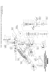
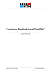
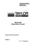
1
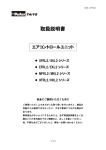
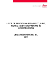
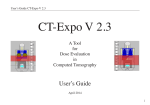
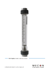
Compact Series
Linear Guide Systems
(Cover)
BEARING OPTIONS
Plain or Ball Bearing Linear Guides
DRIVE TYPE FLEXIBILITY
• Integrated Stepper Motor
• Motor Mount
•Manual
COMPACT
23 mm Low Profile
1-800-962-8979
www.pbclinear.com
MECHATRONICS ENABLED
PBC LINEAR COMPACT SERIES LINEAR GUIDE SYSTEMS
1
Bearing System Options
Gliding Surface Technology
Plain Bearing with FrelonGOLD ®
• LOW COST
• Self-lubricating design
– No sealing
– No particulates
• Tolerates temperature extremes
• Corrosion-resistant
• Industry standard interchangeable
• Vibration damping
• Suitable for an extremely
short stroke
Technical Specifications – Page 10
Lead Screw Options
• 6 mm and 10 mm diameter lead screw
Compact Series
Linear Guide Systems
• Self-lubricating PTFE coated
Nut Options
• Constant Force™ anti-backlash nut
• Standard fixed nut
• Good rigidity and vibration damping
• Self-lubricating and maintenance free
The data and specifications in this publication have been carefully compiled and are believed to be accurate and correct. Specifications are subject to change without notice. It is the responsibility of the user to determine and ensure the suitability of PBC’s products for a specific
application. PBC’s only obligation will be to repair or replace, without charge, any defective components if returned promptly. No liability is assumed beyond such replacement. Other corporate and product names, images, text and logos may be trademarks or copyrights of other
companies and are used only for explanation and to the owners benefit; without intent to infringe. This document may not be reproduced, in part or whole, without the prior written authorization of PBC. Consult www.pbclinear.com for the latest technical updates.
1
COMPACT SERIES LINEAR GUIDE SYSTEMS PBC LINEAR
Bearing System Options
Profile Rail Technology
Ball Bearing Linear Guides
• HIGH RIGIDITY & PRECISION
• High load and moment capacity
• Dust proof design
• Suitable for high speeds
• Supports cantilevered loads
• Low coefficient of friction
Drive Type Flexibility
Integrated Stepper Motor
• NEMA 17 or NEMA 23 motors
• Lead screw aligned and fixed
directly with motor
• Fewer components
means greater
accuracy and
increased rigidity
Motor Mount
• Attach stepper, servo,
or smart motor
Manual Hand Knob
• Hand adjustment knob is used for manually adjusting
screw driven systems
• Compatible with
NEMA 17
and NEMA 23
motor sizes
• One-piece main
frame holds
shaft-to-shaft
centerline
• Easily attached with adapter
plate and coupler
• Assembled system available
with motor and motor mount,
consult factory
www.pbclinear.com I L I N E A R M OT I O N SO LU T I O N S 1
PBC LINEAR COMPACT SERIES LINEAR GUIDE SYSTEMS
1
Applications
MEDICAL AND LABORATORY EQUIPMENT:
The self-lubricating FrelonGOLD® bearing liner, in the plain bearing
option of the Compact Series, is ideal for environments where no
grease or lubrication can be present.
WELL PLATE HANDLING: Compact Series installed in
an intricate well plate handler—providing accurate and reliable
linear motion.
AUTOMATED CONVEYOR: Material handling conveyor
systems utilize the Compact Series linear guide system for
maintenance free, repeatable linear motion.
Integrated stepper motor reduces the number
of components and improves rigidity in the system
2 L I N E A R M OT I O N S O LU T I O N S I www.pbclinear.com
COMPACT SERIES LINEAR GUIDE SYSTEMS PBC LINEAR
1
Applications
SCANNING EQUIPMENT: High precision and smooth
operation are required when designing linear motion for
laboratory scanning equipment. The plain bearing system
utilizes FrelonGOLD ® —a self-lubricating, maintenance free
surface that does not require oil.
CNC ROUTER: The plain bearing version of the Compact
Series is ideal for harsh, dirty environments such as a
CNC router. The carriage acts as a wiper as it clears away
contamination such as dust and debris from the rail.
Plain bearings utilize the bonded FrelonGold®
self-lubricating maintenance-free surface
BOTTLING: The Compact Series is ideal in bottling and food
service applications that require repeatable motion and
involve various load capacities.
www.pbclinear.com I L I N E A R M OT I O N SO LU T I O N S 3
PBC LINEAR COMPACT SERIES LINEAR GUIDE SYSTEMS
1
Three Steps to Design It Your Way
Step 1: Bearing System
Page 5
Step 2: Lead Screw & Nut
Page 6
Gliding Surface Technology
Plain Bearings
Screw Diameters
• 6 mm
• 10 mm
Nut Options:
• Constant Force™
anti-backlash nut
Profile Rail Technology
Ball Bearings
TM
• Standard fixed nut
Step 1
mance
perfor t
t
a
h
W
pec
do I ex e
th
from
em?
s
g yst
bearin
Step 2
crew
lead s
its
best f ion?
c
i
l
p at
my ap
What
Step 3: Motor & Drive Type – NEMA 17 or NEMA 23
Page 7
Integrated Screw & Motor
• Lead screw aligned and fixed
directly with motor
Step
3
What
moto
and
driv r
e typ
do I
e
need
?
Motor Mount
• Attach any stepper, servo,
or smart motor
Design It Your Way . . . . . . . . . . . 4
Step 1: Bearing System Selection . . . . . 5
Step 2: Lead Screw & Nut Options . . . . . 6
Step 3: Drive Type Selection . . . . . . . 7
Bearing Features & Benefits
GST – Plain Bearings . . . . . . . . . . 8
PRT – Ball Bearings . . . . . . . . . . 9
Manual Hand Knob
• Hand knob for
manually adjusting
screw driven system
System Specifications
Dimensions . . . . . . . . . . . . . 10
Performance Charts . . . . . . . . .
12
Ordering . . . . . . . . . . . . . . 13
Motor Mounts
Specifications and Ordering . . . . . .
If you are utilizing our digital Compact Series catalog, you
can click these icons, throughout the publication, to get more
information. Hyperlinks go to English language website.
4 L I N E A R M OT I O N S O LU T I O N S I www.pbclinear.com
15
Dimensions . . . . . . . . . . . . . 16
User Manual . . . . . . . . . . . . .
18
COMPACT SERIES LINEAR GUIDE SYSTEMS PBC LINEAR
1
Bearing System Selection
Step 2
Gliding Surface Technology
PLAIN BEARING
Step 3
• Low cost
• Utilizes bonded FrelonGOLD® bearing surfaces
• Self-lubricating and maintenance free
• No catastrophic failure
• No metal-to-metal contact, vibration damping
• Wide temperature range
• Resists contamination
• 510 mm maximum length
System Ordering Information—Page 13
Step 1
Note: Plain bearings should comply with the 2:1 ratio rule.
White Paper Link: Demystifying the 2:1 Ratio
Profile Rail Technology
BALL BEARING LINEAR GUIDES
• High precision and high speeds
• Size 15 mm bearing block
• Rigid and precise recirculating ball design
• Increased stiffness and preloaded bearing performance
• Supports cantilevered loads
• Low coefficient of friction
• Upgrade to high precision carriage upon availability
• 510 mm maximum length
System Ordering Information—Page 13
UNIFORM DIMENSIONING
PROVIDES DESIGN FLEXIBILITY.
www.pbclinear.com I L I N E A R M OT I O N SO LU T I O N S 5
PBC LINEAR COMPACT SERIES LINEAR GUIDE SYSTEMS
1
Step 1
Lead Screw & Nut Options
Step 2
LEAD SCREW OPTIONS
Step 3
• 6 mm and 10 mm diameter lead screw
• Self-lubricating PTFE coated
• 1, 2, 5, 10 mm leads most common
• Other leads available—consult factory
6 mm diameter
10 mm diameter
Consult Factory for 10 mm Diameter Screw System • 800-962-8979
NUT OPTIONS
Constant Force™ Anti-Backlash Nut
An intuitive leap forward in nut design for lead screw applications,
Constant Force Technology utilizes a constant force spring
to apply a uniform pressure to the nut at all stages of the motion profile.
TM
• Greater consistency and resistance to backlash
• Configurable for various torque requirements
• Patent pending self-adjusting anti-backlash feature
• Polymer nuts are self-lubricating and maintenance free
Standard Fixed Nut
• Good rigidity and vibration damping
• Polymer nuts are self-lubricating
and maintenance free
Video Link: Screws, Nuts, and Hybrid Linear Actuators
6 L I N E A R M OT I O N S O LU T I O N S I www.pbclinear.com
Patent pending Constant Force Technology
nut provides consistent anti-backlash operation
COMPACT SERIES LINEAR GUIDE SYSTEMS PBC LINEAR
1
Motor Type Selection
Step 1
INTEGRATED STEPPER MOTOR
Step 2
• Lead screw aligned and fixed directly with motor
Step 3
• Fewer components means greater accuracy,
increased rigidity, and less cost
• 6 mm and 10 mm diameter
lead screw driven
• NEMA 17 and NEMA 23
motors
• Single and double stack
• Standard wire connection
is onboard plug—included
connector plug with 12" leads
• Longer leads available,
consult factory
Onboard connector plug with 12"
leads included with purchase
System Ordering Information—Page 13
MOTOR MOUNT
• One-piece main frame holds shaft-to-shaft centerline
• Extends motor and coupler life
• Increases accuracy
and repeatability
• Attach NEMA 17 or NEMA 23
stepper, servo, or smart motor
• 6 mm and 10 mm diameter
lead screw driven
• Easy to assemble
• Easily attached with adapter
plate and coupler
• Assembled system available
with motor and motor mount,
consult factory
Motor Mount Details—Page 15
MANUAL HAND KNOB
• Hand adjustment knob is used for manually
adjusting screw driven systems
www.pbclinear.com I L I N E A R M OT I O N SO LU T I O N S 7
PBC LINEAR COMPACT SERIES LINEAR GUIDE SYSTEMS
Bearing System Gliding Surface Technology
Gliding Surface Technology
PLAIN BEARING
OVERVIEW
• Low—23 mm—profile design
• 510 mm maximum length
• Size 15 mm bearing block
• Utilizes the bonded FrelonGOLD® self-lubricating and
maintenance free bearing surfaces
• Smooth and quiet operation
• Vibration damping and shock resistant
LEAD SCREW & NUT
• Lead screw 6 mm and 10 mm diameter,
consult factory for 10 mm
• 300 series stainless steel with PTFE coating
• 1, 2, 5, 10 mm leads most common
• Other leads available—consult factory
• Constant Force™ anti-backlash or standard fixed nut
MOTOR & DRIVE TYPE
Integrated Stepper Motor
• Integrated lead screw eliminates components
and tolerance stack-ups
• Improved rigidity and performance
• Reduced system costs
• Connector with 12" flying leads included
Motor Mount
• Designed to work optimally with R+W EKL2 coupler
Manual Hand knobs
• Hand adjustment knob is used for manually adjusting
screw driven systems
System Ordering Information—Page 13
Motor Mount Details—Page 15
8 L I N E A R M OT I O N S O LU T I O N S I www.pbclinear.com
1
COMPACT SERIES LINEAR GUIDE SYSTEMS PBC LINEAR
1
Profile Rail Technology Bearing
System
Profile Rail Technology
BALL BEARING LINEAR GUIDES
OVERVIEW
• Low—23 mm—profile design
• 510 mm maximum length
• Size 15 mm bearing block
• High precision, rigidity, and speeds
• Increased stiffness and preloaded bearing performance
• Supports cantilevered loads
• Low coefficient of friction
• Upgrade to high precision carriage upon availability
LEAD SCREW & NUT
• Lead screw 6 mm and 10 mm diameter,
consult factory for 10 mm
• 300 series stainless steel with PTFE coating
• 1, 2, 5, 10 mm leads most common
• Other leads available—consult factory
• Constant Force™ anti-backlash or standard fixed nut
MOTOR & DRIVE TYPE
Integrated Stepper Motor
• Integrated lead screw eliminates components
and tolerance stack-ups
• Improved rigidity and performance
• Reduced system costs
• Connector with 12" flying leads included
Motor Mount
• Designed to work optimally with R+W EKL2 coupler
Manual Hand knobs
• Hand adjustment knob is used for manually adjusting
screw driven systems
System Ordering Information—Page 13
Motor Mount Details—Page 15
www.pbclinear.com I L I N E A R M OT I O N SO LU T I O N S 9
PBC LINEAR COMPACT SERIES LINEAR GUIDE SYSTEMS
1
Dimensions GST & PRT System
L + 23
SYSTEM DIMENSIONS
RAIL
6 mm screw system
8
OT shown
CARRIAGE
TOP VIEW
STROKE
OT
15
7.315
Motor Length
(See chart)
OT
15
7.315
Motor Length
(See chart)
Integrated Lead Screw
L + 23
8
RAIL
OT
CARRIAGE
STROKE
54.3
64 (NEMA 17)
71.11 (NEMA 23)
Integrated Lead Screw
52.3 50.8
MOTOR
MOTOR ADAPTER PLATE
54.3
35
50.8
452.3
x M3
x 0.5 x 7 DP TAP
25
45
40 TYP
32
64 (NEMA 17)
71.11 (NEMA 23)
20 Y DIM
MOTOR
M3 SHCS
MOTOR ADAPTER PLATE
35
4 x M3 x 0.5 x 7 DP TAP
25
45
40 TYP
32
20 Y DIM
M3 SHCS
SIDE VIEW
OVERALL LENGTH (See chart)
45
OVERALL LENGTH (See chart)
23 22.3
MOTOR
45
MOTOR
23 22.3
Consult Factory for 10 mm Diameter Screw System • 800-962-8979
48 (NEMA 17)
61.5 (NEMA 23)
48 (NEMA 17)
61.5 (NEMA 23)
Email an Application Engineer
CARRIAGE DETAIL
MOTOR END VIEW (WITH MOTOR MOUNT)
1:1 Shown
6 mm screw system shown
45
TOP VIEW
52.3
MOTOR ADAPTER PLATE
15
MOTOR MOUNT
MAIN FRAME
25
32
SIDE VIEW
35
4 x M3 x 0.5 TAP x 7 DP
Dimensional Information—Page 15
10 L I N E A R M OT I O N S O LU T I O N S I www.pbclinear.com
COMPACT SERIES LINEAR GUIDE SYSTEMS PBC LINEAR
1
Overall System Length
MOTOR LENGTHS (PLUS MOUNTING PLATE)
Motor Size
Single Stack
Double Stack
NEMA 17
39.8 mm
48.3 mm
NEMA 23
57 mm
79 mm
Note:Overall length calculations should include 7.8 mm width for motor mounting plate.
OVERALL LENGTH CALCULATION
Over-Travel Drive End = __________________mm
45
+ Carriage = __________________mm
+ Stroke = __________________mm
+ Over-Travel Idle End = __________________mm
= *Rail = __________________mm
23 (8 + 15)
+ End Blocks = __________________mm
+ Motor & Mounting
Plate Length = __________________mm
= Overall Length = __________________mm
*
Consult Factory for 10 mm Diameter Screw System • 800-962-8979
Rail dimension is specified at time of order
Recommended Minimum Overtravel (OT)
for Compact Series Systems = 10 mm
ONBOARD CONNECTOR PLUG
With 12" Leads Included with Purchase
Onboard connector plug with 12"
leads included with purchase
www.pbclinear.com I L I N E A R M OT I O N SO LU T I O N S 11
PBC LINEAR COMPACT SERIES LINEAR GUIDE SYSTEMS
1
Performance Charts
Fz
Mz
Fy
My
Fx
Mx
GLIDING SURFACE TECHNOLOGY
PROFILE RAIL TECHNOLOGY
1.5
4.2 (with lubrication)
50
5 - 440
3 (requires lubrication)
5.5 (requires lubrication)
250
5 - 440
Ball Bearing Linear Guides
Plain Bearing
Basic System Properties
Max Velocity, no lube, continuous motion
Max Velocity, intermittent motion
Max Acceleration**
Stroke Length (min recommended – max)**
Normal Operating Temperatures (min - max)
Max Drive (input) Speed
Standard Lead Screw Accuracy
Carriage Weight (including four SHCS)
Rail + Screw Weight
System Weight (excluding motor)
m/s
m/s
m/s2
mm
0° - 80°C
2000
ISO Class 10 (± .21 mm/300 mm)
°C
rpm
0.088
0.00058
0.175 + (0.00058/mm * length)
Kg
Kg/mm
Kg
0.115
0.00112
0.242 + (0.00112/mm * length)
Static & Dynamic System Properties
25
Fx
Max Static Load* (Supported Rail)
Carriage Capacity Only
Fy
Fz (Normal)
667
3114
356
N
Fz (Inverted)
25
Fx
Max Dynamic Load of System*
(For PBC supplied motor,
refer to charts below)
Fy
Fz (Normal)
240
240
240
9.0
9.0
15.1
N
Fz (Inverted)
Mx
Max Moments*
5590
5590
5590
My
Nm
Mz
* The above moments and loads are MAX values, please consult our technical department for further information.
** Increased acceleration may be possible in limited cases. Consult factory if exceeding limit.
BUCKLING COLUMN LOAD CURVE
6 mm diameter lead screw
Buckling Column Loading
15625
Buckling Load (N)
3125
625
125
25
Integrated Screw
Stub Sha/Motor Mount
5
1
100
140
180
220
260
300
340
380
420
460
Order Length (Distance Between End Blocks)
500
Note:Based on 500 mm stroke, GST version with .125 C.O.F. and .3G acceleration.
Based on 24 volt, but higher voltage amplifiers may produce higher speeds.
12 L I N E A R M OT I O N S O LU T I O N S I www.pbclinear.com
2500
2500
2500
43.6
27
27
COMPACT SERIES LINEAR GUIDE SYSTEMS PBC LINEAR
1
Ordering Information
CS
XX
15
Series
Rail Type
Compact
Series
MR
Gliding Surface
Technology
Plain Bearing
D -
XX
X
- XXXX -
X
XX
Rail Order
Width Type
Carriage
Preload
Accuracy
Rail
Length
Drive End
Option
Motor Option
D
Driven
00
GST
Precision
0
GST
Rail
510
mm
max
1
Stub Shaft Only
00
No Motor / Stub Shaft Only
15 mm
VO
PRT
Clearance
PR
Profile Rail
Technology
Ball Bearing
AJ - 10
AX - 5
AH - 1
3
Integrated Motor
Screw
XR
X
Lead
mm
AG - 2
A1
NEMA 17 (42 mm)
Single Stack
Consult
factory
for other
leads
A2
NEMA 17 (42 mm)
Double Stack
H
PRT
High
V1
PRT
Light Preload
XX
2
Manual Knob
Consult
factory
for longer
lengths
N
PRT
Normal
-
-
0
Other
Options
Nut
1
Standard
2
Constant
Force
AntiBacklash
0
* Consult
factory
for other
options
such as
encoder
B4
NEMA 23 (56 mm)
Single Stack
1
ZZ
Stub Shaft Only No Motor / Stub Shaft with
Assembled Motor Mount*
Ordering example: CSMR15D-000-0500-3A1-AHXR2-0.
* Motor mount is ordered separately. See page 15 for motor mount ordering details.
Consult Factory for 10 mm Diameter Screw System • 800-962-8979
Email an Application Engineer
VELOCITY LOAD CURVES HORIZONTAL
6 mm and 10 mm diameter lead screw
NEMA 17
Lead Screw NEMA 17 (42 mm) Single Stack Motor (Horizontal)
10 mm 1000
Screw
900
900
800
1mm Lead
700
600
Payload (N)
Payload (N)
800
6 mm
Screw
2mm Lead
500
400
6 mm
Screw
300
600
400
300
200
100
20
40
60
80
Velocity (mm/s)
100
120
140
2mm Lead
500
100
0
1mm Lead
700
200
0
Lead Screw NEMA 17 (42 mm) Double Stack Motor (Horizontal)
10 mm 1000
Screw
0
0
20
40
60
80
100
120
140
160
180
Velocity (mm/s)
NEMA 23
Lead Screw NEMA 23 (56 mm) Single Stack Motor (Horizontal)
10 mm 1000
Screw
900
Payload (N)
800
6 mm
Screw
1mm Lead
2mm Lead
5mm Lead
10mm Lead
700
600
500
400
300
200
100
0
0
50
100
150
200
Velocity (mm/s)
250
300
www.pbclinear.com I L I N E A R M OT I O N SO LU T I O N S 13
PBC LINEAR COMPACT SERIES LINEAR GUIDE SYSTEMS
1
Motor Mount Option Benefits
PBC LINEAR’S DESIGN WITH PRE-ENGINEERED ALIGNMENT
• One-piece main frame holds shaft-to-shaft centerline
• Extends motor and coupler life
• Increases accuracy and repeatability
• Easy to assemble
PBC LINEAR’S DESIGN
VS.
ALTERNATE DESIGNS
PROBLEMATIC DESIGNS CAUSE MIS-ALIGNMENT
• Mis-alignment between motor shaft, coupler,
and screw shortens life and affects motion quality
• Mis-alignment results in camming or lobbing motion that translates
to inconsistent linear movement
• Difficult to align and prone to deflection
• Over-torque of coupler causes accuracy loss
PROBLEM #1: DEFLECTION
PROBLEM #2: TWIST
14 L I N E A R M OT I O N S O LU T I O N S I www.pbclinear.com
PROBLEM #3: OFF CENTERLINE
COMPACT SERIES LINEAR GUIDE SYSTEMS PBC LINEAR
1
Ordering Motor
Compact Series System
Gliding Surface Technology – Plain Bearing
Profile Rail Technology – Ball Bearings
Motor Size
Part Number
Mount Option
Recommended Coupler
Ordered Separately or
Customer Supplied
Included with
Motor Mount Purchase
R + W EKL2
(1) Main frame with 4 SBHCS
(Socket Button Head Cap Screw)
(1) Motor plate with 3 SBHCS
for attaching to frame*
(1) Cover (plastic)
NEMA 17
42 mm
NEMA 23
56 mm
UGA040A-3PMM-HF
UGA040A-3PMM-HG
Maximum coupler dimensions:
25 mm O.D. x 26 mm length
* Customer supplies motor screws
Blank Plate
(customer machined)
UGA040A-3PMM-H0
Cover
Main Frame
Coupler
(purchased separately)
Motor Plate
STUB SHAFT DIMENSIONS
Stub Shaft Diameter
3.5 mm
Overall Stub Shaft Length
15.5 mm
Stub Shaft Length for Coupler Engagement
6 mm
Motor Mount Assembly Procedure—Page 20
MOTOR MOUNT LENGTH (X)
Compact Series
System
X
NEMA 17
42 mm
NEMA 23
56 mm
53.7 mm
54.3 mm
Compact Series
Actuator
Motor Mount
Length
(X)
Motor Length
23
15.5 mm Overall Stub Shaft Length
6 mm Stub Shaft Length
for Coupler Engagement
www.pbclinear.com I L I N E A R M OT I O N SO LU T I O N S 15
PBC LINEAR COMPACT SERIES LINEAR GUIDE SYSTEMS
Motor Mount Option
1
Motor Plate Dimensions
MOTOR SIZE: NEMA 17 (42 MM)
• Material: Anodized aluminum
22 +0.13
0
31
12.8
43
10.8
31
4X
43
3.40 THRU HOLE
MOTOR SIZE: NEMA 23 (56 MM)
• Material: Anodized aluminum
+0.13
38.23 0
22
47.1
56.4
8
35
56.4
System Ordering Information—Page 13
Motor Mount Details—Page 15
16 L I N E A R M OT I O N S O LU T I O N S I www.pbclinear.com
10
4X
4.20 THRU
M5 X 0.8 - 6H THRU
COMPACT SERIES LINEAR GUIDE SYSTEMS PBC LINEAR
1
Blank Plate & Main Frame Dimensions Motor
•
Mount Option
BLANK PLATE
• Intended use: To give customers the ability to machine the plate to match non-standard motor configurations
• Material: Anodized aluminum
• Tip: It is best to locate from the center hole when machining hole pattern for motor attachment.
20
4X 5
60
2
2.50
60
22
15
35
3X
4.50 THRU
MAIN FRAME
• Material: Die cast aluminum, clear chromate
46.0
4X
4.5 THRU
7.5
0.3
31.0
17.6
2 X 1.5
43.0
3X
3.3 11.5
M4 X 0.7 - 6H 8.0
43.0
31.0
2X
15.0
35.0
35.2
2.0
27.0 +0.25
0.00
THRU
www.pbclinear.com I L I N E A R M OT I O N SO LU T I O N S 17
PBC LINEAR COMPACT SERIES LINEAR GUIDE SYSTEMS
User Manual
USER MANUAL TABLE OF CONTENTS
Safety
Tips for Safe Installation and Operation . . . . . . . . . . . . 18
Motor Mount Option
Coupler . . . . . . . . . . . . . . . . . . . . . . . . . . . . . . . . . 19
Assembly . . . . . . . . . . . . . . . . . . . . . . . . . . . . . . . . 20
Maintenance
Lubrication . . . . . . . . . . . . . . . . . . . . . . . . . . . . . . 21
TIPS FOR SAFE INSTALLATION AND OPERATION
• Only qualified personnel should transport, assemble, operate, and maintain this equipment.
• Always wear appropriate personal protection equipment, such as safety glasses and hearing protection.
• Read and observe the installation, operating, and safety instructions provided by the manufacturer. Incorrect handling and
operation may result in damage to equipment and personal injury.
• Comply with all installation specifications and requirements to ensure proper setup.
• Provide a flat and stable mounting surface.
• Be sure sufficient space is provided to permit full carriage travel with no hard stops.
• Be sure power is OFF before performing actuator maintenance.
• The unit should be checked regularly for worn or damaged components. Follow recommended service intervals and replace
defective parts immediately. Always replace parts with the same make and model as the original.
• Be aware that most actuator configurations are not self-braking. A load can move if the drive force is disconnected, or if drive
train components are detached. This is particularly true for vertical applications. The load should be secured prior to service.
Consider installing an electromechanical power-off brake in vertical configurations to prevent potential damage or personal injury.
• Actuators should be wiped down occasionally to keep them clean. Use fluids sparingly and be sure none seeps inside. Do not use
strong or harsh cleaning agents.
• Always test run actuators after maintenance work is completed.
USER MANUAL
• Do not back-drive the lead screw by moving the carriage by hand.
MOUNTING TIPS
• Mount the Compact Series through the holes in the rail
• Counter bores accommodate M3 SHCS
• The number of counter bores varies with the length of rail
18 L I N E A R M OT I O N S O LU T I O N S I www.pbclinear.com
1
COMPACT SERIES LINEAR GUIDE SYSTEMS PBC LINEAR
1
Motor Mount & Coupler Information User
Manual
COUPLER
• Compact Series motor mounts are designed to work optimally with the R+W EKL2 coupler
Verify coupler bore
diameters and depths
will accept both
actuator stub shaft
and motor shaft.
• Other couplers can be used under the following conditions:
• Maximum O.D. = 25 mm
• Maximum length = 26 mm
• Coupler should be sized per the Compact Series actuator.
Compact Series
Actuator
Motor Mount
Length
(X)
Motor Length
23
15.5 mm Overall Stub Shaft Length
6 mm Stub Shaft Length
for Coupler Engagement
STUB SHAFT DIMENSIONS
Stub Shaft Diameter
3.5 mm
Overall Stub Shaft Length
15.5 mm
Stub Shaft Length for Coupler Engagement
6 mm
MOTOR MOUNT LENGTH (X)
NEMA 23
56 mm
53.7 mm
54.3 mm
USER MANUAL
Compact Series
System
X
NEMA 17
42 mm
www.pbclinear.com I L I N E A R M OT I O N SO LU T I O N S 19
PBC LINEAR COMPACT SERIES LINEAR GUIDE SYSTEMS
User Manual
1
Motor Mount Assembly
MOTOR MOUNT ASSEMBLY
TABLE 1
Components:
Hex Key Size Needed:
M3 SHCS = 2.5 mm Driver
M4 SBHCS = 2.5 mm Driver
M5 SHCS = 4 mm Driver
• Base actuator unit
• Motor (customer supplied)
• Motor Mount Kit
TABLE 2
• Motor Plate
• Main Frame
Customer Supplied Fasteners:
NEMA 17 Motor = M3 x 0.5 SHCS
NEMA 23 Motor = M5 x 0.8 SHCS
60 mm Servo Motor = M5 x 0.8 SHCS
• Cover
• Coupler (customer supplied) R + W EKL2 recommended
Fasteners: (9) M4 x 12 mm SBHCS (supplied by PBC Linear),
(4) Customer supplied motor fasteners (See Table 2)
Tools Required: Hex Key (See Table 1)
TABLE 3
Fastener Torque Values:
M3 SHCS = 8-10 in/lb [1.0-1.2 Nm]
M4 SBHCS = 17-21 in/lb [2.0-2.4 Nm]
M5 SHCS = 37-45 in/lb [4.2-5.1 Nm]
Suggested Thread Locker: Blue Loctite ® 242 or equivalent
ASSEMBLY STEPS
1.Slide coupling onto shaft and leave loose.
Step 1
2.Install main frame to actuator end block
using (4) M4 x 12 mm SBHCS. Snug
fasteners, but do not tighten.
3.Install motor plate to main frame using (3)
M4 x 12 mm SBHCS. Apply blue Loctite ®
242 or equivalent threadlocker and torque to
17-21 in/lb [2.0-2.4 Nm] (See Table 3).
USER MANUAL
Step 7
4.Install motor to motor plate with customer
supplied fasteners (See Table 2) and install
shaft into coupling. Snug fasteners, but do
not tighten.
Step 2
Step 3
5.Check for proper shaft engagement on both
sides (per coupler manufacturer specs).
6.Once system is aligned, final torque all
fasteners appropriately (See Table 3).
7.Install cover on pins in casting
(snaps in place).
Step 4
2 0 L I N E A R M OT I O N S O LU T I O N S I www.pbclinear.com
1
COMPACT SERIES LINEAR GUIDE SYSTEMS PBC LINEAR
Lubrication
User Manual
INITIAL LUBRICATION DURING INSTALLATION
Some PBC Linear systems are shipped with a preservative lubrication applied to the raceways. If so, additional lubrication should
be applied during installation. Proper lubrication dissipates heat, increases service life, and reduces friction, wear, and corrosion.
Recommended lubricants are listed where applicable, but there are some lubricants which SHOULD NOT be used on any configuration.
DO NOT USE: WD40; motor oil; oils with additives; moly or other filled greases; PTFE sprays, oils, or greases; or sprays containing
fluorocarbons or silicone.
RECOMMENDED LUBRICANTS
Plain Bearing (GST - Gliding Surface Technology)
Recommended Lubricants: way lube oils, lightweight oils, 3-IN-ONE ® oils, and lightweight petroleum-based greases. The PTFE coated
lead screw and polymer nut require no lubrication during normal operation, but should be routinely inspected for damage and wear. In
certain applications, however, an external lubricant may be desirable. Contact a PBC Linear applications engineer for guidance regarding
additional lubrication.
Profile Rail (PRT - Profile Rail Technology)
Recommended Grease: Synthetic oil based lithium-soap grease with an ISO VG32-100 viscosity.
Recommended Oil: Synthetic oil CLP or CGLP based on DIN 51517, or HLP based on DIN51524.
Viscosity range should be ISO VG32-100.
RELUBRICATION
Linear guide raceways should be relubricated periodically with oil or grease. Recommended lubricants are listed where applicable, but
there are some lubricants which SHOULD NOT be used on any Compact Series configuration.
DO NOT USE: WD40; motor oil; oils with additives; moly or other filled greases; PTFE sprays, oils, or greases; or sprays containing
fluorocarbons or silicone.
The relubrication interval is dependent on many operating and environmental conditions, such as load, stroke, velocity, acceleration,
lubrication type, mounting position/orientation, UV exposure, temperature, and humidity. The actual lubrication interval should be
determined by tests conducted under actual application conditions.
While the actual relubrication intervals are application specific and determined only through testing, the following “first check” guidelines
can typically be used as a starting reference point under “normal” conditions:
Relubrication every 1000 km; 50000 cycles; or six months (whichever occurs first)
Extended Lubrication Interval
Relubrication every 2500 km; 100000 cycles; or one year (whichever comes first)
USER MANUAL
www.pbclinear.com I L I N E A R M OT I O N SO LU T I O N S 21
Worldwide Headquarters
PBC Linear
A Pacific Bearing Co.
European Branch
PBC Lineartechnik GmbH
A Pacific Bearing Co.
Röntgenstr. 8
40699 Erkrath, Germany
6402 E. Rockton Road
Roscoe, IL 61073 USA
Toll-Free:1.800.962.8979
Fax:1.815.389.5790
[email protected]
www.pbclinear.com
www.pbclinear.com
Telefon: 0049 2104 957440 0
Fax: 0049 2104 957440 9
[email protected]
www.pbclinear.de
PBC Linear has a global network of distributors with thousands of locations worldwide.
Visit www.pbclinear.com to find a distributor near you.
DISTRIBUTED BY
© 2015 PBC Linear®, A Pacific Bearing Company • “PBC Linear” and “PBC Lineartechnik GmbH” are subsidiaries of Pacific Bearing Company (“PBC”). The data and specifications in this publication have been carefully compiled and are believed to be accurate and correct.
Specifications are subject to change without notice. It is the responsibility of the user to determine and ensure the suitability of PBC’s products for a specific application. PBC’s only obligation will be to repair or replace, without charge, any defective components if returned promptly.
No liability is assumed beyond such replacement. Other corporate and product names, images, text and logos may be trademarks or copyrights of other companies and are used only for explanation and to the owners benefit; without intent to infringe. This document may not be
reproduced, in part or whole, without the prior written authorization of PBC. Consult www.pbclinear.com for the latest technical updates.
LITCS-001 r1 [2500]