1
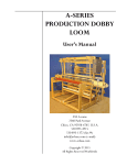
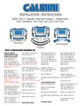
CAL-AV LABS, INC.
Tucson, AZ
www.cal-av.com
USER MANUAL / ASSEMBLY INSTRUCTIONS
DIP-30A
FULL-SIZE 30 METER ROTATABLE DIPOLE
Publication Date: 2000 Oct 15
For Antennas Shipped after 2000 Oct 01
This manual is available at www.cal-av.com
(no copy restriction)
DESCRIPTION:
The DIP-30A is a full-size rotatable dipole for the 30-meter
band. It is noticeably quieter than a vertical. And, when
mounted at the same feed point height, it exhibits both higher
efficiency and more gain (directivity) than an Inverted Vee. It
is about 50 feet in length, and weighs 22 pounds, including all
mounting hardware and the EB-1 balun. In no-ice conditions, wind
survival is 100 MPH. For more details, see Appendices A, B, and
C.
UNPACKING:
Inspect carton for any sign of shipping damage. Then open carton
and inspect contents for hidden damage. Shipping damage is not a
common occurrence, but it does happen. If damage is found, notify
the store, or in the case of direct shipment to you, notify the
carrier.
Remove contents and inventory for the following:
1.
Large bundle of element pieces and mast-to-element mounting
plate
2.
EB-1 Balun Kit
3.
Manual
4.
Hardware Kit
Page 1 of 1
ASSEMBLY:
Tools Required:
A. Combination Wrench, 9/16 inch
B. Screwdriver, Phillips, #2
C. Nut Driver, 3/8"
D.
Hand rivet tool, also known as "POP" or "BLIND" rivet tool.
These are available from tool and hardware stores. Use the
smallest nozzle or hole selection for the 1/8" rivets.
E.
A rope bridle for lifting the assembled antenna
F.
A hoisting rope
G.
One or more "TAG" lines, 3/16" or so, for control of the
antenna while hoisting.
GENERAL:
This antenna has been pre-assembled at the factory and then
disassembled for shipment. However, it may be a good idea to
check the measurements on the elements during assembly. The
important measurements are those of the exposed lengths. That
is, from the outer edge of an element component to the outer edge
of the next larger one. The centermost element pieces (the ones
that include the feed point terminals) are exposed for their
entire length. Element exposed lengths can be found in Appendix D,
Parts List.
Element pieces are swaged (at the last several inches farthest
away from the center) down onto the next smaller diameter element
piece. Sometimes the amount of size reduction due to the swage
is just a few hundredths of an inch, however the swage IS visible.
Beginning with the innermost element piece (near the center) and
going toward the last element piece (the tip), each element piece
fits into the swaged end of the preceding larger diameter piece.
Element pieces have been marked for re-assembly with markings on
both sides of each joint. Beginning with A1-A1 at the Fiberglas
connecting piece, then A2-A2 at the next joint out, then A3-A3,
and so on. The other side of the element begins with B1-B1, and
is marked in a similar pattern.
Page 2 of 2
JOINING PIECES:
Except for the feed point joints, which are fastened with 10-24
screws, assemble joints as follows:
1.
Clean any dirt, dust, or tape residue from the outer surface
of the smaller diameter tubing to be joined. To the extent
possible, also clean the inside surface of the larger
tube. Tape residue may easily be removed with WD-40 or
mineral spirits on a piece of rag or paper towel. Remove any
residue of WD-40 or mineral spirits.
2.
Use the supplied Scotch-Brite pad to clean the surface of the
part of the tube to be mated. This cleaning will produce a
uniform, matte finish.
3.
Wipe down with Methyl Ethyl Ketone (MEK) (preferred) or
Acetone. Either of these is available from most hardware
stores in pint cans. Please read and understand the warnings
on the container regarding use of these solvents.
4.
Apply the supplied silicone grease, working it into the
cleaned surface thoroughly. The amount of silicone grease
needed is just enough to create a film between the two pieces
of metal. The grease serves to prevent galling, to exclude
moisture from between the metal pieces at points of contact,
and to protect the electrical connection from oxidization.
NOTE: Because freshly cleaned aluminum immediately begins to
regrow its
the joints
reason, it
one or two
protective oxide coating, it is important to assemble
within a few minutes of cleaning. For this
may be necessary to clean, grease, and fasten just
joints at a time.
5.
After treatment, assemble the pieces by sliding them
together, with a rotary motion if necessary. Be careful
not to allow any dirt or grit into the joint.
6.
Carefully align the holes. A tapered pin or center punch may
be useful for the initial alignment of the holes. Place
rivets in all three holes before setting any of them. Then,
set them.
NOTE: Rivet holes are semi-random drilled. At the factory, the
joint was correctly assembled; the first hole was drilled,
a rivet installed, then the remaining holes drilled with
the joined pieces unable to move relative to each other.
Then, the one installed rivet was drilled out. This
process results in holes that are as nearly-perfectly
aligned as possible. With this process, every joint in
the assembly is unique and must be reassembled with only
the two original pieces. If the holes do not match
perfectly or very nearly so, then something is wrong, and
the correct parts must be identified and used.
Page 3 of 3
FURTHER NOTE: The elements are joined with closed-end
rivets. The innermost few element pieces are joined with
rivets that have a grip range appropriate for the
combined wall thickness of the tubing involved. The
appropriate rivet part number will be marked on the element
in red.
ELEMENT ASSEMBLY:
Prepare sturdy table or bench for antenna assembly. Unwrap outer
turns of black tape to release 2 smaller telescoped element
pieces. Untape 2 large diameter tubes. Note: tape is best
removed by unwinding. This will result in a minimum of tape
residue on antenna elements. Tape residue on elements can be
removed with mineral spirits or WD-40.
With mast clamp at center of table, note method of pre-assembly of
element A1 to mast connector and mounting plate. Carefully
remove and save screw, nuts and lock-washers from Fiberglas
connector piece. Remove nuts and washers on U-bolt for element
B1 and remove insulator.
Slide insulator over end of element section marked B1. Slide
tube end B1 over Fiberglas connector until the holes in the
Fiberglas and element are aligned. Legend B1 on Fiberglas and
legend B1 on element should be facing in the same direction.
Insert screw for B1 connection in same direction as screw for A1
connection. Nuts, lock washers, and washers should be assembled
to match pre-assembled parts on A1 connection, with 10-24 nuts
closest to fiberglass fully tightened.
Place U-bolt saddle between mounting plate and insulator. Assemble
U-bolt using flanged nuts and lock washer. Do not tighten U-bolt
yet. Loosen U-bolt nuts on A1 connection side and adjust as follows:
2-inch visible section of Fiberglas connector piece between B1 and
A1 tubes should be centered on small hole in mounting plate. Adjust
grey PVC insulators so that they are centered under U-bolts. Rotate
element so that rivets will be at bottom edge when antenna is
mounted on a mast. The heads of the 10-24 screws will be in the
space between the mounting plate and the element, with the nuts
accessible for connecting the balun. Tighten U-bolt nuts by
alternating so that approximately an equal amount of U-bolt is
visible on each side. Continue to tighten until lock-washer is flat
and then 1/2 turn more.
This completes assembly of center section of antenna.
ready to assemble remaining element pieces.
We are now
Continue the process of cleaning, applying silicon grease,
matching markings and holes, and riveting, until both sides of
the element have been assembled.
NOTE: If the antenna is to be painted, this is the time to paint
the element, along with the mast mounting plates and
u-bolts. see Appendix F, "Painting Instructions".
Page 4 of 4
FINAL ASSEMBLY:
NOTE: The space required for this procedure is about 5 feet wide
by 55 feet long. This can be a driveway, rooftop, etc.
putting the element on a couple of sturdy tables will make
this assembly much easier.
Place the element on the element mounting plate and position it
with the long dimension of the plate parallel to the element.
Lay the element onto the plate so that it is centered on the
plate and the PVC insulators are each centered over the holes
for the U-bolts. Install the U-bolts over the PVC insulators,
through the U-bolt clamps, and through the holes in the plate.
The element should be aligned so that when it is in place on the
mast, all rivets will be facing down for drainage, and the 10-24
nuts and washers are accessible for connecting the balun. The nuts
on the U-bolts should be tightened just enough to pull the insulator
snugly into the clamp part of the U-bolt clamp. This is usually
enough torque to just flatten the split-ring lock washer, plus
half a turn more; this also applies to tightening the U-bolt
clamps onto the mast.
NOTE: The most popular mast diameter by far is 2.0" O.D. The Ubolts supplied as standard with the DIP-30A is for this size
mast. If necessary, an element to mast plate for other common
mast sizes can be supplied; contact the factory.
After mounting the antenna, connect the BALUN, and secure it to
the mast in such a way that is not under stress from the
connecting cable. Use silicone grease inside the connecting cable
plug-to-BALUN connection to exclude moisture. (See Appendix G,
BALUN Installation)
Complete painting of the hardware and connections near the mast,
if desired. (See Appendix F, Painting Instructions)
NOTE: Use an adequate number of people, patience, common sense
and great care. These will get your new antenna into the
sky without damage to it or you! If you are not yet
experienced with installation of antennas, we recommend
that you get some experienced help for the first few times.
Then you can help newcomers! BE PARTICULARLY CAREFUL WITH
REGARD TO WORKING ON TOWERS AND NEAR POWER LINES.
Page 5 of 5
APPENDIX A
SPECIFICATIONS DIP-30A
DESCRIPTION
The DIP-30A is a rotatable dipole for the 30-meter amateur band.
It is an unloaded, full size element. It is noticeably quieter
than a vertical, and when mounted at the same feed point height,
exhibits both higher efficiency and more gain than an Inverted
Vee.
It is constructed of multiple sections of 6061-T6 aluminum
tubing. Successively smaller sections are used from the center
toward the tips of the element, resulting in a tapered element.
A mounting plate and hardware which allow mounting the dipole on
a 2" mast are supplied with the antenna. (Mounting plates for
mounting the antenna on other sizes of masts are available from
the factory.) The mounting plate includes insulators which
electrically isolate the split element from the mast mounting
plate. A BALUN for coaxial cable feed is supplied with the
antenna. The BALUN incorporates a UHF receptacle for connection
of the coax's UHF plug (e.g. a PL-259).
PHYSICAL SPECIFICATIONS
Materials
Elements: Aluminum, 6061-T6.
Accessories: Aluminum, Steel, and PVC
Size
Element Diameter: elements taper from 1.875 inches to 0.375
inches
Element Length: 50.75 feet
Element Sag: 16.7 inches
Turn Radius: 25.38 feet
Weight: 21.5 pounds, including mounting plates,
hardware, and supplied (0.5lb) EB-1 BALUN
Projected Area: 4.2 square feet
Page 6 of 6
WIND SURVIVAL
The antenna is designed to reach the maximum allowable stress for
the aluminum material at an actual airspeed across the element in
the worst case direction of 106 Miles Per Hour (MPH). We rate
the element to survive exposure to an airspeed of 100 MPH. This
corresponds to a stress safety factor of 1.12 and does not take
ice loading into account.
When installed at the recommended 46 foot height above
ground, the antenna is rated for operation in a basic wind
speed zone of 100 MPH under UBC-97 (exposure) C.
ELECTRICAL SPECIFICATIONS
Gain: 2.15 dBi, 0 dBd; (this is a full-size dipole)
Feed Point Impedance: Approximately 73 Ohms
(This applies only at resonance and at recommended height
above local earth. Both resonant frequency and the
resistive component of the feed point impedance are
affected by the height above ground. See VSWR Graph
showing theoretical variation in these parameters over
frequency for various mounting heights)
VSWR BANDWIDTH: 2.0 to 1 or less over 600 KHz
The antenna may also be fed with 50-ohm feedline. If it is,
then the minimum VSWR when mounted at the recommended height
will be 1.5 to 1.
NOTE: Please see patterns and graphs for more information
NOTE: CAL-AV reserves the right to make and implement design
improvements without notice.
Specifications updated: 6/06/2000
Page 7 of 7
APPENDIX B
DIP-30A PATTERNS AND GRAPHS
Page 8 of 8
Page 9 of 9
Page 10 of 10
Page 11 of 11
APPENDIX C
DIP-30A MECHANICAL DRAWINGS
Under Construction
Page 12 of 12
Appendix D
DIP-30A - PARTS LIST
MOUNTING PLATE ASSY, consisting of:
1 ea.
Plate, Element to Mast, 6.75"X6"X0.25", 6061-T6,
per drawing #000328-000-0001 REV A.00.0
4 ea.
Clamp assy, 2" nominal, stainless
ELEMENT ASSY, consisting of:
1 ea. center insulating coupling, Fiberglas, 1.5" dia., 8" long
2 ea. screw, 10-24, 2.5" long, Phillips pan head, stainless
8 ea. washer, flat, AN-960-10, stainless
4 ea. washer, lock, split-ring, #10, stainless
2 ea. insulator, element mounting, 1.75" nominal I.D.
2 ea. tube, 1.875" dia., 0.125 wall, 58" overall,58" exposed
2 ea. tube, 1.50" dia., 0.095 wall, 45" overall, 42" exposed
2 ea. tube, 1.25" dia., 0.083 wall, 62" overall, 59" exposed
2 ea. tube, 1.00" dia., 0.049 wall, 18" overall, 15" exposed
2 ea. tube, 0.875" dia., 0.049 wall, 18" overall, 15" exposed
2 ea. tube, 0.75" dia., 0.049 wall, 21" overall, 18" exposed
2 ea. tube, 0.625" dia., 0.049 wall, 22" overall, 19" exposed
2 ea. tube, 0.50" dia., 0.049 wall, 30" overall, 27" exposed
2 ea. tube, 0.375" dia., 0.035 wall, 58" overall, 55" exposed
NOTE: All element tubing material is 6061-T6
12 ea. Rivet, Aluminum, closed end, Emhart
AD55H, 5/32" dia.
6 ea. Rivet, Aluminum, closed end, Emhart
AD53H, 5/32" dia.
30 ea Rivet, Aluminum, closed end, Emhart
AD42H, 1/8" dia.
Note: Rivets used to fasten joints A2 / B2 out to A4 / B4,
inclusive, are 5/32" diameter. The rivet part number
is marked in red on each joint. The remaining joints
use AD42H rivets (1/8" diameter).
1 ea.
BALUN, Cal-Av Labs Model EB-1, with installation kit.
Page 13 of 13
APPENDIX E
OPERATIONAL NOTES
FEEDPOINT IMPEDANCE
This is a function of height above ground. The feed point
impedance of a dipole in free space is approximately 73 ohms. As
a horizontal dipole is raised from just above the ground, its
impedance increases from a very low value, (less than 20 ohms)
through the free-space value of 73 ohms at half a wavelength
above effective ground, then to a value significantly above 73
ohms, then back through 73 ohms at one wavelength above ground,
and so on, oscillating about the 73-ohm value at each half
wavelength. The excursions of these oscillations become smaller
and smaller as the height becomes remote from the ground. (see
Appendix B, Patterns and Graphs) For vertical operation with the
lower tip of an element just above ground, say 0.02 wavelength,
the feed point impedance is just under 100 ohms.
VSWR
Because of the characteristic impedance vs. height, the minimum
VSWR will vary. At a half wave above effective ground, the
antenna will yield a VSWR of 1:1 when fed with a 72-ohm feed
system. (e.g. a tuner, followed with RG-11 to the antenna) For
most installations, which are 50-ohm systems, the minimum VSWR
will be about 1.4:1. This is of no importance unless the feed
line is very lossy. For runs of more than 50 feet to the
antenna, we recommend a high-quality, large size cable such as
LMR-400 or RG-213.
TAKE-OFF ANGLE CONTROL, NVIS OPERATION
For single lobes broadside to the element, the antenna should be
operated one-half wavelength above effective ground. This is
probably the best all-purpose height. As the dipole is raised
above this height, secondary lobes will begin to develop, and the
center of the main lobes will drop to a lower angle.
To raise the take-off angle for Near-Vertical-Incidence-Skywave
(NVIS) operation, the dipole should be lowered to a quarter wave
above effective ground. This will produce a broad, vertical lobe
that is practically omni-directional, and which will produce
gap-free communication out to several hundred miles when
ionospheric conditions support NVIS operation on this band. If a
lower antenna height is desired for improved signal-to-noise
during NVIS operation, then a separate, low height receiving
antenna should be used. Lowering the transmitting antenna below
a height of one eighth of a wavelength will greatly increase
losses due to absorption by the earth.
Page 14 of 14
APPENDIX F
PAINTING INSTRUCTIONS
GENERAL:
Should you paint your antenna?
Here are the facts:
We think so, but it's your decision.
OPERATIONAL EFFECTS:
Nil; a thin dielectric coating (paint) between the metal and the
air does cause changes, but they would be very difficult to
measure for antennas of this size. A slight reduction in
precipitation static may be noticed.
ADVANTAGES:
There are two primary advantages to painting an antenna:
First, its visual impact is mitigated, because the recommended
paint is flat, eliminating the "glint" associated with aluminum,
even so-called low glare treatments. Further, the recommended
paint is very close to the color and gray-scale of power company
pole-mounted transformers and modern insulators; this results in
it not being too dark against a light sky, nor too light against
a dark sky.
Second, it is protected from weathering, particularly if its
surrounding area is subject to contaminants that would attack
aluminum. (sea air, acid rain, etc.)
Other advantages include: cleaner handling (bare aluminum can be
really dirty stuff!), protection and easy-to-disassemble locking
of mounting hardware, protection of cables, baluns, etc. from the
effects of sunlight, and as mentioned above, some reduction of
static from raindrops.
DISADVANTAGES:
Labor and cost of painting materials.
Materials Required:
1. "Scotch-Brite" pad, general purpose hand pad, maroon.
This pad is included with each antenna in the hardware
Kit.
2. Clean soft rags or paper towels.
3. Acetone or Methyl-Ethyl-Ketone (MEK) (latter preferred)
Page 15 of 15
PAINTING:
1.
Follow the instructions (other than for surface prep) on the
can. Be sure to use several even, light sprays, close enough
to produce a wet (shiny) coat, but not so thick that it runs.
Touch-up can be at any time. A second coat is recommended
at least 15 minutes after the first.
2.
For the element, a good approach is to spray one side, then the
other. When dry enough to handle, rotate the element 90
degrees and spray each side in the new position (what were
the top and the bottom).
3.
Mask off any connection that will be made after the element
is attached, as well as the feed point connector. Remember,
that if you goof, this primer can be removed with an
acetone-dampened rag.
4.
Light Gray Primer, Rust-Oleum No. 2081. Available at Home
Depot, large hardware stores, and some paint stores.
No recommended substitutes at this time.
BACKGROUND:
1.
This primer is light gray, a color that is being used more
and more for power-pole insulators, transformers, etc., for
looking less obtrusive against an average sky.
2.
Read instructions on paint can thoroughly; disregard the part
about surface preparation, which was written for steel
automotive bodies. This particular primer has some very nice
attributes: Among them are that it can easily be removed with
acetone, even after it is dry, and that it is very easy to
touch up, while wet, after it's dry, or days later. It will
oxidize a bit after years in the sun; even then, it can be
cleaned with an MEK-dampened rag, just enough to remove dirt
and some of the oxidized paint, and then repainted. We
recommend two coats, at least 15 minutes apart.
SURFACE PREPARATION:
1.
In this case, the surfaces to be painted are stainless steel
and aluminum plate and tubing.
2.
The hardware can just be wiped down with MEK and allowed to
dry before painting.
3.
The aluminum plate should be cleaned with Scotch-Brite to a
dull, uniform finish, then washed with MEK until no more
aluminum residue shows on the cleaning towel. The plate can
then be hung using a piece of wire and painted.
Page 16 of 16
4.
The element is prepared for painting after assembly.
Balance it on a stepladder step so that it is about chest high.
Wipe the element down with a rag dampened with MEK. Be sure to
remove any silicone grease residue. Be careful not to let the
MEK drain into the joints. Clean the exposed surfaces of the
entire element using a Scotch-Brite pad. Clean to produce a
uniform, matte finish. Then wipe down with MEK until no more
aluminum residue shows on the cleaning towel.
Page 17 of 17
APPENDIX G
INSTALLATION PROCEDURE - EB-1 BALUN
GENERAL DESCRIPTION:
The EB-1 is an external bead balun. It is constructed of a length
of teflon coaxial cable surrounded by 50 ferrite beads. At one end
of the cable is a UHF coax connector that mates with the popular
PL-259 cable-end connector; at the other end are wire leads to
facilitate connection to a dipole or driven element. The wire
leads are color-coded for ease of phasing multiple elements or
antennas; white = coax center. CAL-AV LABS’ baluns are vacuum
impregnated and sealed against weather. The exterior surface is
paintable. Freq. range: 1.8 through 60 Mhz. Power: 2,500W, CW;
3,000W PEP. See derating schedule overleaf.
A balun’s purpose is to allow connecting a BALanced load (e.g., a
dipole or driven element) to an UNbalanced line, thus the name.
In transmitting antennas, this is accomplished by presenting a high
impedance to RF currents flowing outside the coax shield. This
forces currents in each side of a driven element to be equal. This
is especially important in beam antennas because it prevents
distortion of the beam’s pattern caused by unequal currents in the
driver(s). In a simple dipole, the balun assures that the dipole,
and not the feed line, is doing the radiating.
POSITION ON ANTENNA:
The balun should be oriented perpendicular to the driven element.
On beams, after connection to the driven element, it is usually
secured to the main boom using the black UV-resistant ties
provided. For wire antennas, run the coax cable perpendicular to
the wire (usually straight down) as far as practicable, at least
several feet. Further, on wire dipoles, tie the balun up to the
center insulator with dacron line, etc. to take any stress off the
balun’s wire leads. Also, tie the coax up to the insulator to
relieve stress on the coax connector.
An adapter plate that
serves this purpose and acts as a center insulator for wire dipoles
is available from CAL-AV LABS.
PREPARATION OF LEADS:
For beams, cut leads to just reach the edge of the attaching screws
for the driven element plus a very small additional length to allow
reattachment of a terminal if it is damaged, etc. Keep balun lead
length to a minimum. If leads must be made longer than 2 inches,
then twist them together. Run them up to the feed point, where they
should then separate and go directly away from each other and
connect to the antenna terminals. Check to make sure the terminals
supplied will fit the beam manufacturers hardware. The terminals
Page 18 of 18
supplied are for #8 or # 10 studs. (8-32, 10-24 screws, etc.) We
recommend lightly crimping the terminals to the wire then
soldering, using rosin flux solder. This will produce a good, gas
tight connection. For wire antennas, you may want to solder the
leads directly to the wire on either side of the center insulator
or adapter plate. Do NOT use the EB-1 by itself as a center
insulator!
CONNECTIONS:
Connect the terminals to the driven element and tighten the
hardware snugly. Spray with a water repellent / corrosion
inhibitor if desired, or paint, however, do not “seal” in such a
way that water can be trapped.
On the coax end, put a small amount of silicone grease on and
around the pin of the PL-259 plug, insert it into the balun and
tighten firmly with finger-torque only. do not use pliers. The
coax connection may be sealed with coax seal if desired, however,
the silicon grease will exclude water from entering. Make sure
that no silicone grease gets on the outer surface of the coax plug
if coax seal is to be used.
PAINTING:
The balun may be painted either before installation, taking care to
mask off the coax connector, or it may be painted in place on the
beam. Rust Oleum TM gray automotive primer is great for this
purpose - it is very fast drying. In fact, it is rather wonderful
for getting rid of the reflectivity (glint) of the entire beam!
Painting the balun will improve its resistance to “sunburn.”
Page 19 of 19