1
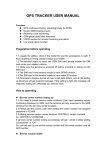
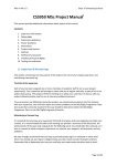
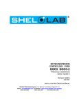
This SHEL LAB Product is Manufactured by
Sheldon Manufacturing Inc.
PO Box 627 Cornelius, OR 97113
Toll Free: (800)322-4897 • Phone: (503)640-3000 • Fax: (503)640-1366
email: [email protected]
web site: www.shellab.com
The SHEL LAB
High Heat Decontamination
CO2 Incubator
Installation & Operation Manual
This Manual Applies to
the Following Models:
3552
3552-2
High Heat
Decontamination
CO2 Incubators
4861611
02/2012
Page
1
Table of Contents
Table of Contents
Section
1
2
3
4
5
6
7
8
9
10
11
12
13
14
15
Subject
Important Manufacturer Recommendations
CO2 Incubator Overview
Receiving and Inspecting Your CO2 Incubator
Graphic Symbols Glossary
Installation of your CO2 Incubator
Control Panel Overview
Operating Your SHEL LAB CO2 Incubator
CO2 Supply and Control System
Monitoring of CO2 Levels
Decontamination Cycle Operation
CO2 Incubator Maintenance Instructions
Trouble Shooting
Replacement Parts
Unit Specifications
Wiring Diagram
SHELDON MFG INC.
300 N. 26th Ave. Cornelius, OR 97113
1-800-322-4897 503-640-3000 Fax 503-640-1366
Visit our web site at www.shellab.com
CO2 Incubators • Vacuum Ovens • Water Baths • Incubators • Ovens
Low Temperature Incubators • Humidity Test Chambers • Shaking Incubators
Bactron Anaerobic Chambers • Hybridization Ovens • Shaking Water Baths
4861611
04/2011
Page 2
Return to Table of Contents
SECTION
Important Manufacturer
Recommendations
1
Before you use the unit, read this entire manual carefully to understand how to install, operate,
and maintain the unit in a safe manner. Your satisfaction with the unit will be maximized as you read
about its safety and operational features.
Thank you for choosing a SHEL LAB C02 Incubator. These units are not intended for use at
hazardous or household locations.
Keep this manual on-hand so it can be used by all operators of the unit. Be sure all operators of the
unit are given appropriate training before you put the unit in service.
Note: Use the unit only in the way described in this manual. Failure to follow the guidelines and
instructions in this manual may be dangerous and illegal.
Important Safety Information
Your CO2 Incubator and its recommended accessories have been designed and tested to meet strict
safety requirements.
For continued safe operation of your C02 Incubator, always follow basic safety precautions including:
• Read this entire manual before using the C02 Incubator.
• Be sure you follow any city, county, or other ordinances in your area regarding the use of this unit.
• Use only approved accessories. Do not modify system components. Any alterations or
modifications to your CO2 Incubator may be dangerous and will void your warranty.
• Always plug the unit’s power cord into a grounded electrical outlet that conforms to national and
local electrical codes. If the unit is not grounded, parts such as knobs and controls may conduct
electricity and cause serious injury.
• Do not connect the unit to a power source of any other voltage or frequency beyond the range
stated on the power rating overlay or data plate on the inside of the door (see next page). Do not
modify the power cord provided with the unit. If the plug does not fit an outlet, have a proper outlet
installed by a qualified electrician.
• Avoid damaging the power cord. Do not bend it excessively, step on it, place heavy objects on it.
A damaged cord can easily become a shock or fire hazard. Never use a power cord after it has
become damaged.
• Do not stack units without use of a stacking rack.
Page 3
Return to Table of Contents
Quick Links
Receiving & Inspection
Installation Details
SECTION
SHEL LAB CO2 Incubator
Overview
2
Complete Control
Panel Overview
Welcome! Thank You for Purchasing a SHEL LAB CO2 Incubator
This Page is an Overview of the Features Built Into Your New CO2 Incubator.
Over Temperature Limit
Control
Temperature
Control & Display
Over Temperature Activated Light
Alarm Contacts Relay
CO2 Sample Port
USB Port
Power Switch
Decontamination Cycle Control &
Display
Stainless Steel Shelving
Stainless Steel Humidity Pan with
Anti-microbial Copper Token
Sheldon Manufacturing Inc.
P.O. Box 627
Cornelius, Oregon 97113
EMAIL: [email protected] WEB SITE: http://www.Shellab.com
PHONE: 1-800-322-4897 (503) 640-3000 FAX: (503) 640-1366
Page 4
CO2 Control &
Display
Side Access Port with
Copper Filter
Return to Table of Contents
SECTION
Receiving & Inspecting
Your SHEL LAB CO2 Incubator
3
Receiving Your SHEL LAB Unit
All units are packaged with high-quality shipping materials to provide protection from transportation related
damage.
However, once a unit leaves the factory safe delivery is the responsibility of the carrier who is liable for loss or
damage to your unit. Damage sustained during transit is not covered under your unit warranty.
Carefully inspect the shipping carton for damage. If the carton is damaged, report the damage to the carrier
service that delivered the unit.
If the carton is not damaged, open the carton and remove its contents.
Inspection Guidelines
When you receive your unit, inspect it for concealed loss or damage to its interior and exterior. Should you find
any damage to the unit, follow the carrier’s procedure for claiming damage or loss.
Verify that all of the following equipment is included in the crate using the: See Ship Kit Details Next Page
(Page 6)
Save the shipping carton until you are sure everything is in order.
Returning Shipment
If you must return the unit for any reason, first contact your service representative for authorization. You will be
asked to provide the data plate information.
Recording Data Plate Information
Once you have determined the unit is free from damage, locate the data plate inside the door of the unit. The
data plate indicates your unit’s model number and serial number. Record this information for future reference.
Login to www.shellab.com and complete the warranty registration or return the Warranty Registration Card part
#8660505.
Page 5
Return to Table of Contents
Ship Kit Items
Option items to purchase for your
unit.
5170646
2002-S
5121028
2700506
1800510 110V
7150509
3350000
995-00015
9000575
9710500
3
Accessory Items
Verify all items listed on this page are received while unpacking your unit.
5121109
SECTION
Receiving & Inspecting
Continued
9000574
1800500 220V
9750582
5820504 (shelf)
5820505 (slide)
Description
Quantity
Part
Number
Description
Quantity
5121109
Stainless Steel Shelving
3
2002-S
Tank Switcher
1
5170646
Stainless Steel Shelf Standards
4
7150509
Regulator
1
Fyrite Kit
1
Part Number
5121028
Stainless Steel Shelf Slides
6
3350000
2700506
Leveling Feet
4
9000575
Stacking Stand
1
995-00015
Stainless Steel Humidity Pan w/Antimicrobial Copper Token (5800529)
1
9000574
1
9710500
CO2 Tubing Kit: Includes Black
Tubing, Clear Tubing, & CO2 Disc
HEPA Filters (Shown Above 100199)
1
Caster Platform
Copper Shelf Assemby
(5820504 3 Shelves)
(5820505 6 Slides)
1800510 (110V)
1800500 (220V)
Power Cords
1
9750582
Manual
4861611
1
Warranty Card
8660505
1
To be sure that your accessories kit is complete,
check inside packaging materials for loose items and
always keep them with the unit.
Page 6
1
Return to Table of Contents
SECTION
Graphic Symbols Glossary
4
Graphic Symbols Glossary
Indicates that you should consult your operator’s manual for further
instructions.
Indique que l’opérateur doit consulter le manuel d’utilisation pour y trouver
les instructions complémentaires.
Indicates “Temperature”
Repère “température”
Indicates “Overtemperature Limit”
Signale un “dépassement de température”
Indicates “Degrees Celsius”
Indique les “Degrés Centigrades”
Indicates “Carbon Dioxide”
Indique le “Dioxyde de Carbone”
Indicates “Gas” (Carbon Dioxide for the unit)
Indique le “gaz” (CO2 pou cet appareil).
Indicates “AC Power”
Repère “secteur AC”
Indicates “ON / I” and “OFF / O”
Indique “MARCHEI” et “ARRET O”
Indicates “Protective Earthground”
Repère de la “terre de protection”
Indicates “Potential Shock Hazard” behind partition
Signale un “risque potentiel d’électrocution” au-delà de la cloison.
Indicates “Unit should be recycled” (Not disposed of in land-fill)
Indique “l’appareil doit être recyclé“ (Ne pas jeter dans une décharge)
Indicates “Warning: Hot Surface”
Signale un “Avertissement: Surface chaude”
Page 7
Return to Table of Contents
SECTION
Installation of Your CO2 Incubator
5
NOTE: The recommended operating environment for this equipment is 5 - 30°C with a Relative Humidity
of less than 80%. Supply voltage should not vary more than ± 10% from the data plate rating. Contact
customer service for operating conditions outside of these limits.
Power Source
The unit power requirements are listed on the data plate. Check the data plate for voltage, cycle, and
ampere requirements. Plug the power cord into a PROPERLY GROUNDED (earthed) Power source
OF THE CORRECT SIZE AND STYLE INDICATED ON THE UNIT NAMEPLATE RATING. A separate
circuit is recommended for this unit to prevent loss of product due to overloading or circuit failures
caused by other equipment. The supply voltage must match the nameplate voltage within +/- 10%.
Location
In selecting a location, consider all conditions that might affect performance, such as heat from radiators, ovens,
autoclaves, etc. Avoid direct sun, fast-moving air currents, heating and cooling ducts, and high traffic areas. Allow
a minimum of 2 1/2” (10 cm) between the unit and any walls or partitions that might obstruct free airflow and to
promote easy access to the power cord and source. Under normal circumstances this unit is intended for use indoors.
Lifting and Handling
CAUTION: Use appropriate lifting devices that are sufficiently rated for these loads. Failure to do so
could result in minor or moderate injury.
AVERTISSEMENT: Utilisez des dispositifs de levage de charge nominale suffisante pour ces poids. Le
non respect de cette consigne pourrait provoquer des blessures légères ou modérées
Units should only be lifted from their bottom surfaces. Handles and knobs are not adequate for lifting or stabilization. The unit should be completely restrained from tipping during lifting or transport. All moving parts such as trays
or covers should be removed during transfer to prevent shifting and damage.
Leveling
The unit must sit level and solidly. Leveling feet (#2700506) are supplied and must be installed in the four
holes in the bottom corners of the unit. With the feet installed and the unit standing upright, each foot can be
raised by turning it in a counterclockwise direction. Adjust the foot at each corner until the unit stands level
and solid without rocking. If the unit must be moved, turn the all four (4) leveling feet clockwise until snug to
avoid damaging the bottom of the incubator while sliding. Use of Caster Plateform (#9000574) will aide
in moving the unit. The leveling feet will not need to be adjusted if using the caster platform for moving.
Page 8
Return to Table of Contents
SECTION
Installation Continued
5
Cleaning
Appropriate lab practice includes cleaning and disinfecting the unit prior to use. Your operating conditions and
documented lab protocol will determine the correct procedure for cleaning. A typical cleaning procedure is described below and will help reduce the likelihood of contamination and the necessity of decontamination. Clean
the unit regularly. Depending on usage and protocol, this may be monthly or quarterly.
Cleaning the unit does not qualify the unit as decontaminated. Decontamination Cycle Operation is detailed in
Section 10.
NOTICE: Follow these precautions regardless of cleaning procedure. Failure to do so may cause
property damage and void your warranty.
•
Always disconnect the unit from the electrical service when cleaning.
•
Assure all volatile or flammable cleaners are evaporated and dry before reconnecting the unit to the
power supply.
•
Special care should be taken when cleaning around sensing heads to prevent damage.
•
Do not use chlorine-based bleaches or abrasive cleaners. These will modify the stainless steel interior
finish.
•
Do not use hard tools such as metal wire brushes or steel wool. Use non-abrasive cleaners and soft
tools such as plastic brushes.
Typical CO2 Incubator Cleaning Procedure
1. Remove the humidity pan every week, wash with soap and water, and then disinfect with 70% alcohol
solution. Replace in the incubator with fresh, DISTILLED water.
2. Flush the sample port tubing with 70% alcohol solution. Replace any lines that have a green color.
3. Remove all shelves, shelf supports, shelf standards and shields. Wash and disinfect as described in item 1.
For initial set up, clean and disinfect shelving parts prior to installation. Refer to page 10 for detailed shelving
installation.
4. Wash and disinfect all interior surfaces.
5. Give special attention to cleaning and disinfecting all access ports, air bleeds, shaft holes, electrical passthrough and any other passages into the chamber.
6. Replace all air and CO2 filters every six months or when noticeably dirty on the upstream side. CO2 filters are
located in the shadow box just behind the GAS IN fitting and in line with the CO2 tubing kit.
Page 9
Return to Table of Contents
SECTION
Installation Continued
5
Installation Tips for Minimizing CO2 Incubator Contamination
•
Keep the outside of the incubator, including the air in the laboratory, as clean as possible.
•
Do not place incubators near doors, air vents or other areas of high air movement or traffic.
•
The floor around the CO2 Incubator should be kept as clean as possible.
•
Units that are placed on the floor should be on a caster platform (#9900574) to make moving the unit easier
during cleaning and when accessing the back of the unit.
•
Minimize the number of times access is made to the chamber during normal operation.
•
Do not depend on the use of antibiotics to maintain uncontaminated conditions, as this is an inadequate
technique for decontamination.
•
Use aseptic techniques as described above for maintaining decontaminated conditions in the incubator
Installing Shelving and Humidity Pan
Completely remove protective vinyl coating from shelving apparatus and disinfect prior to installation.
2
3
SHELVING
1
Install Shelf Slide (#5121028) by aligning with Shelf
Standards (#5170646) at a slight upward angle and
set into a level position.
HUMIDITY
Install Shelf Standards
(#5170646)
by aligning the keyhole
with the peg on the
Page 10
Install Humidity Pan (#995-00015)
by placing directly on the chamber
floor.
Slide Shelves (#5121109)
into position
with bent ends facing up.
Return to Table of Contents
SECTION
Front Control Panel Overview
6
CONTROL PANEL OVERVIEW
Set Over Temp Control
1. Over Temperature Limit Control
4. Over Temperature Activated Light
Over
Temp
2. Alarm Output Jack
Alarm Contacts
5. CO2 Sample Port
CO2 Sample Port
USB
3. USB Port
FRONT CONTROL PANEL FEATURE DESCRIPTIONS
Controls are located on the front panel. Units with a detachable cord have a fused inlet located at the top rear of
the incubator. This inlet has a recessed male plug, fuse and an EMI filtering system designed to filter out electrical
interference. This inlet also prevents any internally generated interference from feeding out to the power grid.
Set CO2%
Set Temperature ºC
Decontamination Cycle Switch
CO2 Injecting
1. Over Temperature
Limit
Control
(OTL):
This
limit
device
is
a
back
up
mechanical
temperature thermostat wired
Heating Activated
Decon Cycle
into the
temperature monitoring system toHigh
secure the incubator temperature is maintained in case of a faiure in
High
Acticated
the main
microprocessor temperature controller.
This OTL is set by the incubator user.Decon
See
Section 7-Setting
Mute
Mute
the Over Temperature Limit Control Thermostat.
Normal Operation
Low
Low
2. Alarm Output Jack: This contact connector allows a remote alarm to be connected
to Selecor
the unit.
Operation
Switch
3. USB Port: This is a standard USB computer connection port for logging unit performance of temperature and
Power
CO2 S
CO2 levels. Click here to download the data logging software available for this unit.
180ºC Hight Heat Decontamination
ERIES
SheTemperature
don Ma nufac turing
4. Over Temperature
Activated Light: This green pilot lamp turns on whenever the Over
LimitInc. ®
!
Thermostat has been activated and taken control of the heating element. During normal operating conditions
this indicator should never be on.
5. CO2 Sample Port: Independently meausre the CO2 content in the incubator chamber using this sample port.
Page 11
Return to Table of Contents
2. Main Temperature Control
4. Main CO2 Control &
CO2 Injecting Light
3. Heating Activated Light
Temperature
Display
SECTION
Front Control Panel Continued
65
5. Decontamination
Cycle Switch
7. Decontamination
Control Panel Lights
CO2
Display
Operation Selector Switch
1. Power Switch
“I” = on, “O” = off
6. Operation Selector Switch
FRONT CONTROL PANEL FEATURE DESCRIPTIONS (continued)
1. Power Switch: The I/O (ON/OFF) switch controls all of the power for the incubator and must be in the I/ON
position before any systems are operational. Both temperature and CO2 displays will illuminate when the
power switch is in the I/ON position.
2. Main Temperature Control: This controller is marked “Set Temperature ˚C” and indicates the temperature
within the chamber.
3. Heat Activated Light: This green pilot lamp turns on when the elements are on and heating the chamber.
4. Main CO2 Control: This controller is marked “Set CO2 %” and indicates the percentage of CO2
content within the chamber to 0.1%. NOTE: This display will become the countdown timer during the
decontamination cycle.
CO2 Injecting Light: This green pilot lamp turns on when the CO2 controller is injecting CO2 into the
chamber.
5. Decontamination Cycle Switch: This is located on the right side of the control panel. It controls the high
temperature decontamination cycle. The cycle will not start until the operation selector switch is pushed
placing the unit in decontamination operation mode.
6. Operation Selector Switch: This button is used to activate the high temperature decontamination cycle.
The decontamination cycle cannot be started unless operation selector switch has been pushed placing
the incubator in decontamination mode.
Page 12
Return to Table of Contents
SECTION
Front Control Panel Continued
65
7. Decontamination Control Panel Indicator Lights:
Decon Cycle Light: This amber colored light is located at the top of the three lights. It indicates when
the unit is in the decontamination mode.
Decon Activated Light: This red colored light is between the normal operation indicator light and the
decon cycle light. It indicates the unit is actively running a decontamination cycle.
Normal Operation Light: This green colored light is located at he bottom of the three lights. It indicates
the unit is operating in the normal incubator mode.
Page 13
Return to Table of Contents
SECTION
SHEL LAB CO2 Incubator
Operation Instructions
75
Operating the Controls: Refer to the Control Panel Overview of this manual for a list of terms used.
Power: Verify that your incoming electrical power supply is compatible with the electrical specifications on the
incubator data plate. Do not use an incoming electrical power supply that will under power or over power the
incubator. Doing so may cause damage to the incubator circuitry which will void the warranty.
Set the power switch to the I/ON position. If this is the first time your new incubator is being set up the temperature control and CO2 control will fuction to the factory setting of temperature set at 37 C and CO2 set to
OFF. The Temperature Control will display the ambient chamber temperature and immedicately begin to heat
the incubator to the factory preset of 37 C. The green heating indicator light will illuminate and the temperature
will begin to rise on the display. The CO2 Control Display will initially show 20% CO2 and begin counting down
in varying increments to 0.1% CO2, this is the offset reading for the factory preset at OFF. NOTE: Operating
temperature must be set, achieved, and calibrated before CO2 connection and adjustments are made.
Leave the CO2 setting in the OFF set point while bringing the incubator to your temperature set point.
Initial Control Settings: Each SHEL LAB CO2 Incubator comes preset from the factory at 37C and the CO2 set
to off. You should allow the incubator to heat up and stabilize for 24 hours. Turn the overtemperature control
clockwise until it stops so that it does not activate during the initial warm up.
Muting Audible Alarms: Powering the unit on prior to calibration may activate the built in alarm system. To mute
the alarm hold EITHER the up or down button until the “mute” indicator activates.
Calibrating the Controls for Temperature or CO2:
1. Push and hold both the UP and DOWN buttons simultaneously for five (5) seconds.
a. If you are calibrating temperature, the Temperature Display panel will read “CO” and then blink.
b. If you are calibrating CO2 Level, the CO2 will read “CO” and then blink.
2. While the display is blinking use the UP and DOWN buttons to adjust the display to match the actual
condition in the incubator chamber.
3. If no buttons are pressed within five (5) seconds the blinking will stop and the display will revert to showing the process or actual parameter within the incubator chamber.
Establishing Temperature Set Point: Your new incubator comes factory preset with a temperature set point of
37 C. If this is your desired set point there is no need to change anythng and you can let the incubator heat to
37 C and skip ahead to Calibrating Temperature. To verify the temperature set point on your already employed
incuator while it is operating pressing either the Up or DOWN arrow on the Temperature Display for an instant
and release, the display will read SP for a moment and then flash the current set point for a few seconds and
then go back to a constant display of the current chamber temperature.
Changing Temperature Set Point: Press either the Up or DOWN arrows on the Temperature Display for an
instant and release, the display will read SP for a moment and then flash the current set point. While the set
point is flashing use the UP or DOWN arrows on the Temperature Display to change the temperature to your
desired set point. The temperature adjusts in 0.1 C increments. Once you have the temperature display set to
your desired set point the display will flash the set point a few times and then change to a constant display of
the current incubator chamber temperature reading. If the current reading is lower than your desired set point
the indubator will be heating to your set point. Heating is indicated by the illumination of the green pilot light
marked “Heating Activated” on the Temperature Control Section of the panel. You will soon see a rise in the
Temperature Display. If the current reading is higher than your desired set point the incubator will sit idle until it
cools to your set point. TIP: To help cool the incubator open the door momentarily to release the heat in
the incubator chamber.
Page 14
Return to Table of Contents
SECTION
SHEL LAB CO2 Incubator
Operation Instructions
Continued
7
Checking Temperature Settings: Perform the calibration in the following order:
Main Temperature Calibration -> Setting the Temperature -> Setting Over Temperature Safety.
1. During main temperature calibration do not open the inner glass door for any reason. Open the outer
heated door as little as possible.
2. After the incubator has been running for 24 hours and the temperature display is stable at the set point,
read the temperature in the chamber using a reference thermometer. If necessary, recalibrate the display.
3. After the main temperature display has stabilized again and maintained set point for several hours, check
the actual temperature again. If it does not match the display repeat the calibration.
4. After the Main Temperature is set and adjusted, the Overtemperature Limit Control needs to be set.
Setting the Over Temperature Limit Control Thermostat: This should be done AFTER the main temperature
control is set and the unit has stabilized. Raise the Set Point 1 degree above desired Set Point. After it has
stabilized, turn the safety knob counterclockwise until the OTP Light illuminates. Then, return the Set Point
back to the desired Set Point. This sets the Safety at 1°C above Set Point.
Setting the CO2:
1. Push and release either the UP or DOWN button and the digital display will blink “SP” and then a number
which is the setpoint.
2. While the display is blinking the set point can be changed using the UP or DOWN buttons.
3. If no buttons are pressed within five (5) seconds the blinking will stop and the display will revert to showing
the process or actual parameter within the incubator chamber.
Humidification Preparation: Humidification of the incubator is achieved by evaporation of distilled water in the
chamber using a Humidity Pan (#995-00015) filled with distilled water placed in the bottom of the incubator
chamber. By allowing the distilled water to heat and evaporate near saturation humidity is achieved. Place
the SL Copper Fixture (#5800529) under the clip in the Humidity Pan (#995-00015). The SL Copper Fixure in
Humidity Pan (#995-00015) serves as a anitimicrobial measure to reduce the ability of bacteria to grow in the
water. Place Humidity Pan (995-00015) with attached Copper Fixture (#5800529) on the bottom inside of the
incubator chamber. Fill the Humidity Pan (#995-00015) with distilled water. NOTE: USE DISTILLED WATER
ONLY.
NOTICE: To ensure the proper operation, verify the accuracy of the temperature and CO2 controls regularly.
Temperature can be confirmed by using a thermometer inside of the chamber. CO2 levels can be confirmed with
the use of a Fyrite Gas Analyzer (#3350000) or other equipment such as a gas chromatograph. Failure to do
so may damage the unit and void your warranty. Contact a SHEL LAB Technical Support at 1-800-322-4897 for
questions. A 0-20% Gas Anayzer kit (#3350000), 0-7% Fyrite Gas Analyser Kit (#3350501), or handheld digital
C02 Gas Analyzer (#8050506) can be purchased on the SHEL LAB website www.shellab.com or call Customer
Service at 1-800-322-4897.
Page 15
Return to Table of Contents
SECTION
SHEL LAB CO2 Incubator
Operation Instructions
Continued
75
Humidity Levels in the Incubator: Humidification of the incubator chamber is achieved by evaporation of water
from the chamber humidity pan placed in the bottom of the incubator. By filling this stainless steel reservoir pan
with DISTILLED WATER ONLY and allowing this water supply to heat and evaporate, near saturation humidity
is obtained.
NOTICE: Follow the Humidity Preparation precautions below. Failure to do so may damage the
incubator and void your warranty.
•
Use Distilled Water Only. DO NOT USE DEIONIZED WATER.
•
Do not use plastic, glass or other metals as substitute humidity pans. Only 300 series stainless
steel is acceptable for this reservoir pan.
•
Do not use corrosive chemicals including copper sulfate or chlorine in the pan or chamber as
damage to the interior may occur.
•
Be aware that the use of disinfecting chemicals mixed in the distilled water can change the surface
tension of the distilled water thus preventing the evaporation and proper humidification of the
chamber. The distilled water in the pan should be changed and the pan cleaned at least once a
week to help control contamination and maintain proper surface tension and evaporation. Keeping
the SL Copper Fixture (#5800529) in the Humidity Pan will aid in reducing the spread of bacteria in
the reservoir. See Routine Maintenance for further details.
Independent Temperature Monitoring: To insure the incubator when operating is at the desired temperature, an
accurate independent temperature monitoring device is required such as a certified thermometer or a certified
temperature indicator. Place a reference thermometer of your choice at the center just above the centermost
shelf inside the incubator. Avoid having the thermometer touch the shelf as it may cause an inaccurate
reading when touching the shelf. TIP: Taping a thermometer to the top of a petri dish keeps the thermometer
from touching the shelf, keeps it from rolling, and keeps the scale in view. You may use a digital temperature
display with a probe using the side access port on the incubator for placing the probe at the enter of the
centermost shelf in the indubator. Be sure the sensor in the probe is just off the shelf for a reliable reading.
Position the digital display in a convenient place where it will be easily visible outside the incubator. Digital
thermometers with remote displays are idea because they can be read without opening the doors. Be sure
your digital thermometer is rated for 95% relative humidity atmosphere.
Page 16
Return to Table of Contents
SECTION
CO2 Supply & Control System
8
CO2 Supply System and Control System: The CO2 system is rated for pressures between 15 to 20 PSI and
should never be exceeded at any time.
C02 GAS INLET
IN BACK
GAS FILTER
PRESSURE
REGULATOR
SOLENOID
1/4” RESTRICTOR
ASSY
OUT
IN
PUMP
IR SENSOR
CHAMBER
SAMPLE PORT
IN FRONT
Connecting CO2 to the Incubator: The CO2 inlet fitting is located at the back of the unit near the top (see
above image). It is marked CO2 TO CHAMBER.
A supply hose with in-line CO2 filter (supplied with your accessories) connects from the fitting to a CO2 tank
and regulator.
Page 17
Return to Table of Contents
SECTION
CO2 Supply & Control System
Continued
85
CO2 Regulator Considerations: Ensure that you are using a dual stage regulator.
It is highly recommended that a good quality 0-40 PSI output range DUAL STAGE pressure regulator be
used on the CO2 tank. The dual stage regulator will have two pressure gauges. The high pressure gauge
(0-4000 PSI) will indicate the pressure within the tank. The low pressure gauge (0-40 PSI) will indicate the
output pressure on the supply hose to the incubator. Single stage regulators do not provide as stable performance as dual stage.
Reading & Understanding Your CO2 Tank Levels: It is normal for the high pressure gauge on your regulator
to start out reading 800 to 1000 PSI with a full tank. The reading will drop from 800 to 500 PSI quickly and
will stay there for most of the duration of the tank. At the end of use, the pressure will drop quickly to zero
to indicate that the tank is completely empty. Pure CO2 is in a liquid state in the tank, and a constant vapor
pressure is generated in the tank above the liquid level. The CO2 is drawn off of the top as a gas. The same
vapor pressure is maintained as long as any liquid is left in the tank. When the last of the liquid has evaporated into gas then the pressure will drop rapidly as the gas is drawn off.
NOTICE: Only medical grade CO2 should be used in your incubator. Failure to do so may damage
the unit and void your warranty.
Manufacturer’s Recommendation for Monitoring CO2 Levels: CO2 sensors are factory calibrated and, under
normal circumstances, need no calibration. It is recommended that the accuracy of your CO2 control system be monitored by measuring the actual CO2 concentration on a weekly basis with a Fyrite or other
measuring device. This should be done when the chamber has not been opened for an extended period of
time, i.e. after the weekend, and should only take 1-2 hours.
Setting the CO2 Control: Attach the supply hose from the CO2 tank to the incubator CO2 inlet fitting and
turn on the CO2 supply. Set the CO2 control to the desired set point using the up and down arrows (section
7 page 15). The CO2 level comes from the factory preset to OFF.
Adjusting CO2 Display: After the incubator has had several hours to stabilize at CO2 set point, measure the
actual CO2% with a Fyrite. If there is any difference between the Fyrite and the display, use the
procedure described in section 7 page 14 for calibrating CO2. See Section 9 Page 19 (next page) for Fyrite
use and instruction.
NOTE: When using the Fyrite, insure that gas is not being injected while the reading is being taken. Always
change the CO2 set point to 0.0 prior to taking the sample and change the set point back to the desired
value after the use of the Fyrite is finished.
Page 18
Return to Table of Contents
SECTION
Monitoring of CO2 Levels
95
Using a FYRITE to Measure CO2 Levels
A Bacharach FYRITE CO2 Gas Analyzer is recommended to measure CO2 concentrations in the incubator chamber. This test instrument is not supplied with the incubator but is readily available from your
dealer. Follow the instructions provided with each Fyrite instrument carefully to ensure correct and accurate readings.
Fyrite Quick Overview
1. Press button on top of Fyrite canister to release CO2 concentration. Release button and tip
canister to the side to ensure all fluid is released from the top of the canister. Return canister to the
upright position.
2. Loosen screw on slide scale and align top of fluid with zero on the scale. Tighten screw.
3. Connect hose and aspirator bulb to unit being tested. The sample port for connection is located on the
control panel.
4. Place the hose sampling cap directly over the plunger valve on top of the canister and depress firmly.
5. With button depressed, squeeze bulb 20 times. On the last squeeze and with bulb still deflated,
release hose from button.
6. Turn Fyrite canister upside down 3 times, each time allowing all fluid to flow to the opposite end of the
canister.
7. Tilt canister to the 45 degree position to ensure all fluid has been released from top of canister. Return
canister to the upright position.
8. Read CO2 concentration in %.
WARNING: The fluid used inside this fyrite instrument is poisonous and corrosive. If taken
internally could result in serious injury or death. The fyrite indicator will come with a complete set
of detailed instructions which should be followed carefully. In the event of a spill or accidental body
contact with the fyrite fluid, follow the instructions on the refill bottle carefully.
MISE EN GARDE: Le liquide utilisé par cet instrument fyrite est toxique et corrosif. Son ingestion
pourrait causer des blessures graves ou provoquer la mort. L’indicateur fyrite est livré avec un
ensemble complet d’instructions détaillées à suivre attentivement. En cas de déversement du
liquide fyrite ou contact accidentel avec le corps, suivez les instructions de la bouteille de recharge
attentivement.
Page 19
Return to Table of Contents
SECTION
Decontamination Cycle
Operation
5
10
Although this unit was run through a Decontamination Cycle after manufacturing, it is highly recommended
that a Decontamination Cycle be run prior to using the unit. After following the cleaning procedure detailed on
page 9, and all accessories have been cleaned and installed into the unit, begin the Decontamination Cycle
using the following instructions:
1. To Activate Decontamination Cycle: Press and hold down the lower Operation Selector Switch until the
green Normal Operation Light goes out and the amber Decontamination Cycle Light starts to flash.
NOTE: If neither Decontamination Cycle Switch nor Operation Selector Switch is depressed within one (1)
minute, the amber Decon Cycle Light will go out and the green Normal Operation Light will come on.
2. To start the Decontamination Cycle, press and hold the Decontamination Cycle Button when the amber
Decontamination Cycle Light is flashing. You will hear a thump of the door locking. The Door will remain
locked until the unit has cooled down to 50°C at the END of the Cool down phase noted below.
3. During the warm up to decontamination temperature the amber Decontamination Cycle Light and the red
Decontamination Activated Light will flash alternately.
4. At all times the Temperature Display will indicate the actual temperature within the incubator chamber.
During the Decontamination Cycle warm up, the CO2 display will read “dEC” for Decontamination Cycle
until the Chamber Temperature reaches 180°C. Under normal operating conditions, the Decon Cycle warm
up to 180°C will take up to 1 ½ hours.
5. After the Chamber Temperature reaches 180°C, the CO2 display will switch to a count-down timer
indicating the number of minutes remaining from 120 to 0. During the timed portion of the cycle, the red
Decon Activated light and the amber Decontamination Cycle light will be continuously lit.
6. At the end of the two (2) hour 180°C Decontamination Period, the cool down portion of the
Decontamination Cycle will automatically start.
7. During cool down cycle, the CO2 Display will read “CdN”. The amber Decontamination Cycle light and the
green Normal Operation light will flash alternately indicating that the Decon Cycle has been successfully
maintained at 180°C for two (2) hours and the unit is cooling down to normal incubation temperature. The
door will remained latched until temperature reaches 50°C.
8. To go back into Normal Operation Mode, depress the lower Operation Selector Button and hold it down
until the amber Decontamination activated light stops flashing and the green Normal Operation Light stays
on solid.
9. If at any time during the Decon Cycle you wish to abort the Decon Cycle, press and hold down
simultaneously both Operation Selector Buttons until the amber Decontamination Cycle Light stays on and
the red Decontamination Activated Light stays off. If temperature is above set point, alarm will sound. See
section 5 page 13 for alarm controls.
NOTE: DO NOT attempt to open door until deactivation is completed. Green flashing lights will indicate the
door is unlocked and you will hear a distinct thump.
Page 20
Return to Table of Contents
SECTION
Decontamination Cycle
Operation Continued
5
10
The following chart covers the various meanings of the light displays during the unit’s current operating
condition.
Unit Condition and Relative Light Display
CONDITION
CO2 DISPLAY
AMBER
RED
GREEN
Normal Operation
% CO2
OFF
OFF
ON
Decon Operation
Cycle Not Started
% CO2
FLASHING
OFF
OFF
Warming up to 180ºC
dEC
Alternately Flashing Alternately Flashing
OFF
Decon Cycle Running at 180º C for 2
Countdown From
120 to 0 Min.
ON
ON
OFF
Cool Down to 50º C
Cdn
OFF
OFF
FLASHING
Decon Cycle
Successful
PAS
OFF
OFF
FLASHING
Decon Cycle
Manually Aborted
Ab
ON
OFF
OFF
Decon Cycle Failed
FL
ON
OFF
OFF
Page 21
Return to Table of Contents
SECTION
SHEL LAB CO2 Incubator
Maintenance Instructions
5
11
Warning: Prior to any maintenance or service on this unit , disconnect the power cord from the
power source. Before reattaching the unit to its power source , be sure all volatile and flammable
cleaners are evaporated and dry.
Avertissement:
Avant d’effectuer toute maintenance ou entretien de cet appareil, débrancher le cordon
secteur de la source d’alimentation. Avant de reconnecter l’appareil sur le secteur, s’assurer que tous les
produits de nettoyage volatiles et inflammables sont complètement évaporés.
Chamber Cleaning: Cleaning and decontamination are recommended on a regular basis. To prepare the
incubator for cleaning remove all interior parts such as the shelf standards and false top. Please review the
Cleaning procedures described in the Installation section for detailed instructions.
Monitor CO2 Levels: Check CO2 supply periodically; don’t let it run out. Automatic tank switches and “empty
tank” alarms are available from your dealer.
Keeping the CO2 flow system free of impurities: Inconsistent levels of CO2 control are usually traceable to the
CO2 pressure regulator on the tank, impurities in the tank, or impurities in the solenoid valve. Replace the CO2
in-line filters every six (6) months or when the filters have become noticeably dirty on the upstream side. There
is a CO2 filter attached to the tubing kit, and one inside the shadow box connected to the GAS-IN line.
Microprocessor Controls: There is no maintenance required on any controls. If the controls fail to operate
as specified, we recommend powering the unit down, waiting a 10 seconds and turning it back on. Contact
customer service if this doesn’t resolve the issue.
Proper Storage of Your SHEL LAB CO2 Incubator: If the incubator is to be turned off for any length of time,
dry the chamber and humidity pan thoroughly and leave at room temperature. Failure to do this may cause the
interior to become contaminated. No adjustment to controls should be required when restarting the unit. If the
unit is to be shut down for transport, remove humidity pan and shelves, dry the chamber and disconnect the
CO2 and power supplies. See section 5 pages 8-9 for lifting, handling, and transport procedures.
Page 22
Return to Table of Contents
SECTION
Troubleshooting
5
12
Temperature
Temperature too high
1. Controller set too high - see section 7, Setting the Temperature
2. Controller failed on – call Customer Service.
Temperature too low
1. Over temperature too low – see section 7, Setting the Over Temperature Limit
2. Controller set too low - see section 7, Setting the Temperature
3. Unit has not recovered from power failure or being turned off - incubator needs to warm up and
stabilize for 8 hours
4. Unit has not recovered from door opening - wait for the display to stop changing
5. Element Failure - see if the heating light is on and compare current draw to the data plate information
6. Controller failure - confirm with front panel lights that controller is calling for heat
7. Thermostat failure - confirm with front panel lights that Over Temperature is operating correctly
Unit will not heat over a temperature that is below set point
1. Confirm that the set point is set high enough - turn the Over Temperature Safety Control
counterclockwise and see if HEATING or OVERTEMP lights are illuminated
2. Check the calibration - this can be done by using an independent, certified reference thermometer
and by following the instructions in section 7, Calibrating The Temperature
Unit does not heat up at all
1. Verify that controller is asking for heat by looking for HEATING light display - if pilot light is not
on during the entire initial start up, there is a problem with the controller
2. Check amperage
3. Do all of the controller functions work? - if not contact Customer Service
4. Is the Over Temperature Thermostat set high enough? - For diagnostics, the Over Temperature Safety
Control should be turned clockwise until it stops with the pilot light never on
5. Check to see if the fuse or circuit has blown
Chamber temperature unstable
1. +/- 0.1 is normal variance
2. Is the ambient room temperature radically changing? This could be a result of a number of things:
Door opening too often, room airflow from heaters or air conditioning - stabilize ambient conditions
3. Calibration sensitivity - contact Customer Service
4. Over Temperature Thermostat is set too low - check if pilot light is on continuously. Turn controller
knob completely clockwise to see if problem is solved, then follow instructions in section 7 for setting
Over Temperature Limit.
Unit will not maintain set point
1. Assure that set point is at least 5 degrees over ambient room temperature
2. See if ambient temperature is fluctuating. If so stabilize
Cannot adjust set points or calibration
1. Reset entire unit by turning off and then on. If happens repeatedly, contact Customer Service
Page 23
Return to Table of Contents
CO2 Level
SECTION
Troubleshooting Continued
5
12
Overshoots set point but stabilizes - display and fyrite match
1. Tank pressure is too high, see section 8
2. CO2 sensor is partially plugged with dirt or condensation - contact Customer Service
3. Regulator is set wrong, see section 8
4. Pump filter partially plugged - contact Customer Service
Overshoots set point and continues to rise - display and fyrite match
1. Debris in solenoid causing it to leak continuously - contact Customer Service
2. Solenoid failed while open - contact Customer Service
3. Controller output failed or shorted - contact Customer Service
4. CO2 sensor or interface failure - contact Customer Service
5. CO2 sensor plugged by debris or condensation - contact Customer Service
Rises very slowly
1. Filter is too dirty or partially plugged - replace filter
2. Hose is kinked or leaking - repair or replace hoses
3. CO2 tank regulator set too low - see section 8
4. Poor or faulty door seal - call customer service
5. CO2 tank regulator turned off - turn on regulator
Never Rises
1. CO2 filter plugged - replace CO2 filters
2. CO2 hose blocked - repair or replace hose
3. CO2 tank empty - change tank
4. CO2 controller ouput failed while open - contact Customer Service
5. Solenoid failed while closed - contact Customer Service
6. Set point is at 0.0 and has not been reset - see section 7
7. CO2 tank regulator is not on - turn on regulator
If unstable - display or actual reading varies around set point
1. Door not sealing properly - check door seal
2. Defective tubing - check tubing and replace if necessary
3. Top of unit is exposed to cold air drafts - check the unit’s position and move the unit to appropriate
spot
4. Unit being operated without shadow box cover
5. Incubator is too heavily loaded
Page 24
Return to Table of Contents
SECTION
Troubleshooting Continued
5
12
CO2 Level Continued
Display and Fyrite reading do not match
1. Calibration error - see section 7
2. CO2 sensor, interface, or controller failure - contact Customer Service
Set points or calibration is “locked up” and can not be adjusted
1. Turn unit off and on to reset processor in controller
2. If it happens repeatedly - contact Customer Service
Will not hold calibration - display stable but Fyrite reading varies
1. Top of unit exposed to cold air drafts
2. Unit is being operated without shadow box cover in place
3. Condensation collecting on CO2 sensor
4. CO2 sensor or interface failure
5. Unit is incorrectly calibrated - see section 7
6. Taking fyrite reading too soon after the door has been opened
Mechanical / Other
Door not sealing
1. Check physical condition of gasket
2. Confirm that door latch pulls door tightly
3. Assure gasket is in original location
Controller is on at all times and “locked up”
1. Turn unit off and on to reset. If condition on front panel can not be changed, call Customer Service
Front panel displays are all off
1. Make sure unit is plugged in, check fuse, power switch, and power supply
Unit or wall fuse/circuit breaker is blown
1. Check wall power source and see what other loads are on wall circuit
Unit will not turn on
1. Check power source - check fuse and circuit breaker on unit or in wall and check power switch
Contamination in chamber
1. See cleaning procedure in Section 11. Develop and follow standard operating procedure for
specific application: include cleaning technique and maintenance schedule
Page 25
Return to Table of Contents
Description (Listed Alphabetically)
Access Port Stopper
CO2 Display Board
CO2 Filter
Copper Fixture
Decontamination Cycle Display Board
Decontamination Temperature Limit Thermostat
Door Heater (Internal)
Door Switch
(Stops CO2 from injecting when door is open)
Element Assembly
Air Jacket Circulating Fan Blade
Fan Motor
Fan Muffin 12vdc
Gasket, 8 Feet (seals against viewing door)
Glass Door Assembly
Humidity Pan with Copper Fixture
Digital IR CO2 Sensor
Leveling Feet
Main Control Board
Motor Cooling Fan Blade
Over Temperature Protection Thermostat
Outer Door Gasket
Power cord inlet fuse 12.5 amp 250v / 15amp 110v
Pilot Light, Red
Power Cord US 120v / EU 230v
Power Supply 12vdc
Power Switch
Pump Sampling
Recorder Jack
Shelf
Solenoid Valve 12vdc
Temperature Display Board
Temperature Probes
USB Interconnect Board
Page 26
Part Number for 120V
SECTION
SHEL LAB CO2 Incubator
Replacement Part Numbers
11
13
7750565
1750819
2800525
5800529
1750820
1750759
2350529
Part Number for
230V
7750565
1750819
2800525
5800529
1750820
1750759
2350528
7850578
7850578
9570926
2600502
4880527
1850515
3450644
9521195
995-00015
9570927
2600502
4880528
1850515
3450644
9521195
995-00015
8320512
2700506
1750821
2600545
1750862
3450534
3300520
4650553
1800510
6750507
7850553
6700558
6900522
5121109
8600560
1750818
6600520
1750846
8320512
2700506
1750821
2600545
1750862
3450534
3300516
4650553
1800500
6750507
7850553
6700559
6900522
5121109
8600560
1750818
6600520
1750846
Return to Table of Contents
SECTION
SHEL LAB CO2 Incubator
Unit Specifications
Model Number
Interior Dimensions
WxDxH
Exterior Dimensions
WxDxH
Chamber Capacity
3552 & 3552-2
20.5 x 20 x 25.25 (in)
51.44 x 20 x 25.25 (cm)
28.75 x 30.25x 39.25 (in)
73.03 x 76.64 x 99.70 (cm)
164 cubic liters
14
Model Number
Shipping Weight
Net Weight
3552 & 3552-2
275 lbs (127kg)
237 lbs (100 kg)
Model Number
Temperature Range
Control
Temperature Uniformity
CO2 Range
3552 & 3552-2
Ambient +5°C to 50°C
+/- 0.1°C
+/-0.25°C @ 37°C
0 - 20%
Decontamination Temperature is 180°C for 120 minutes.
Model Number
Amperage
Voltage
Hertz
Fuse
3552
12.0 Amp.
110-120 VAC
50/60 Hz
12.5 A
3552-2
6.0 Amp.
220-240 VAC
50/60 Hz
10.0 A
Page 27
Return to Table of Contents
Page 28
SECTION
Wiring Diagram for Models
3552 (9851257)
15
Return to Table of Contents
SECTION
Wiring Diagram for Models
3552-2 (9851256)
15
Page 29