1
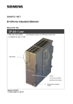
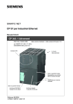
SIMATIC NET
S7-CPs for Industrial Ethernet
Manual Part B
CP 343-1 Lean
6GK7 343−1CX10−0XE0
as of hardware version 2, as of firmware version V2.2
for SIMATIC S7−300 / C7−300
LEDs
TP port:
2 x 8-pin RJ-45 jack
(beneath the front panel)
X = Placeholder for hardware
version
Release 09/2009
C79000-G8976-C198-06
Notes on the product
Notes on the product
Product names
This description contains information on the following product
S
CP 343−1 Lean
Order number 6GK7 343−1CX10−0XE0
as of hardware version 2 and firmware version V2.2
for SIMATIC S7−300 / C7−300
Note
In this document, the term CP is used instead of the full product name.
Compatibility with the previous version
Note
Make sure that you read the information regarding extended functions and
restrictions in Chapter 7 of this manual!
Address label: Unique MAC address preset for the CP
The CP ships with a factory-set MAC address. The MAC address is printed on the
housing.
-
B−2
CP 343-1 Lean for Industrial Ethernet / Manual Part B
Release 09/2009
C79000-G8976-C198-06
Contents
Contents
Contents − Part A
Ethernet CPs − general information . . . . . . . . . . . . . . . . . . .
see general part
Note
Please remember that Part A of the device manual also belongs to the description
of the CP. Among other things, it contains explanations of the safety notices and
general information that applies to all S7 CPs for Industrial Ethernet.
Part A of the manual release 05/2008 and this Part B belong together
You can download the general Part from the Internet:
http://support.automation.siemens.com/WW/view/en/30374198
Contents − Part B
1
2
3
Properties / Services . . . . . . . . . . . . . . . . . . . . . . . . . . . . . . . . . . . . . . . . . . . . . . . . . . .
B−5
1.1
Application . . . . . . . . . . . . . . . . . . . . . . . . . . . . . . . . . . . . . . . . . . . . . . . . . .
B−5
1.2
Communication services . . . . . . . . . . . . . . . . . . . . . . . . . . . . . . . . . . . . . .
B−5
1.3
Other services . . . . . . . . . . . . . . . . . . . . . . . . . . . . . . . . . . . . . . . . . . . . . . .
B−6
Requirements for Use . . . . . . . . . . . . . . . . . . . . . . . . . . . . . . . . . . . . . . . . . . . . . . . . . .
B−8
2.1
Operation in controller device families . . . . . . . . . . . . . . . . . . . . . . . . . . .
B−8
2.2
Configuration . . . . . . . . . . . . . . . . . . . . . . . . . . . . . . . . . . . . . . . . . . . . . . . .
B−11
2.3
Programming . . . . . . . . . . . . . . . . . . . . . . . . . . . . . . . . . . . . . . . . . . . . . . . .
B−11
Installation and Commissioning . . . . . . . . . . . . . . . . . . . . . . . . . . . . . . . . . . . . . . . . .
B−13
3.1
Procedure / steps . . . . . . . . . . . . . . . . . . . . . . . . . . . . . . . . . . . . . . . . . . . .
B−13
3.2
Module replacement without PG . . . . . . . . . . . . . . . . . . . . . . . . . . . . . . . .
B−16
3.3
Controlling the operating mode . . . . . . . . . . . . . . . . . . . . . . . . . . . . . . . . .
B−17
4
LED Displays . . . . . . . . . . . . . . . . . . . . . . . . . . . . . . . . . . . . . . . . . . . . . . . . . . . . . . . . . .
B−18
5
Performance Data / Operation . . . . . . . . . . . . . . . . . . . . . . . . . . . . . . . . . . . . . . . . . . .
B−22
5.1
Number of possible connections over Ethernet . . . . . . . . . . . . . . . . . . .
B−22
5.2
Characteristic data for S7 communication . . . . . . . . . . . . . . . . . . . . . . . .
B−23
5.3
Characteristics of the SEND/RECEIVE interface . . . . . . . . . . . . . . . . . .
B−24
5.4
5.4.1
5.4.2
PROFINET IO . . . . . . . . . . . . . . . . . . . . . . . . . . . . . . . . . . . . . . . . . . . . . . .
Characteristic data . . . . . . . . . . . . . . . . . . . . . . . . . . . . . . . . . . . . . . . . . . .
Operating PROFINET IO alongside other services . . . . . . . . . . . . . . . .
B−25
B−25
B−26
CP 343-1 Lean for Industrial Ethernet / Manual Part B
Release 09/2009
C79000-G8976-C198-06
B−3
Contents
5.4.3
Effects of multicast communication on RT communication . . . . . . . . .
B−26
5.5
Characteristic data of the integrated switch . . . . . . . . . . . . . . . . . . . . . .
B−27
6
The CP as Web server . . . . . . . . . . . . . . . . . . . . . . . . . . . . . . . . . . . . . . . . . . . . . . . . . .
B−28
7
Compatibility with Predecessor Products . . . . . . . . . . . . . . . . . . . . . . . . . . . . . . . .
B−29
8
7.1
Enhanced functions . . . . . . . . . . . . . . . . . . . . . . . . . . . . . . . . . . . . . . . . . . .
B−29
7.2
Replacing older modules: spares / upgrading . . . . . . . . . . . . . . . . . . . . .
B−30
Further Notes on Operation . . . . . . . . . . . . . . . . . . . . . . . . . . . . . . . . . . . . . . . . . . . . .
B−32
8.1
Clear/reset and Reset to factory settings . . . . . . . . . . . . . . . . . . . . . . . .
B−32
8.2
Network settings with Fast Ethernet . . . . . . . . . . . . . . . . . . . . . . . . . . . . .
B−33
8.3
Influence of MPI on connections via Industrial Ethernet . . . . . . . . . . . .
B−35
8.4
8.4.1
8.4.2
IP configuration . . . . . . . . . . . . . . . . . . . . . . . . . . . . . . . . . . . . . . . . . . . . . .
Detection of double IP addressing in the network . . . . . . . . . . . . . . . . .
Obtaining the IP address over DHCP: CP STOP on expiry of the
lease . . . . . . . . . . . . . . . . . . . . . . . . . . . . . . . . . . . . . . . . . . . . . . . . . . . . . . .
B−36
B−36
8.5
Media redundancy . . . . . . . . . . . . . . . . . . . . . . . . . . . . . . . . . . . . . . . . . . . .
B−37
8.6
Time-of-day synchronization . . . . . . . . . . . . . . . . . . . . . . . . . . . . . . . . . . .
B−37
8.7
SNMP agent . . . . . . . . . . . . . . . . . . . . . . . . . . . . . . . . . . . . . . . . . . . . . . . . .
B−39
8.8
Possible security gaps on standard IT interfaces: preventing illegal
access . . . . . . . . . . . . . . . . . . . . . . . . . . . . . . . . . . . . . . . . . . . . . . . . . . . . . .
B−40
8.9
8.9.1
Interface in the user program . . . . . . . . . . . . . . . . . . . . . . . . . . . . . . . . . .
Programmed communication connections with FB55 IP_CONFIG
(PROFINET interface) . . . . . . . . . . . . . . . . . . . . . . . . . . . . . . . . . . . . . . . .
Programmed communications connections − Assigning parameters to
the ports . . . . . . . . . . . . . . . . . . . . . . . . . . . . . . . . . . . . . . . . . . . . . . . . . . . .
8.9.2
B−36
B−41
B−41
B−42
9
How to Load New Firmware . . . . . . . . . . . . . . . . . . . . . . . . . . . . . . . . . . . . . . . . . . . . .
B−43
10
Technical Specifications . . . . . . . . . . . . . . . . . . . . . . . . . . . . . . . . . . . . . . . . . . . . . . .
B−44
11
Other Information available about the CP . . . . . . . . . . . . . . . . . . . . . . . . . . . . . . .
B−45
12
References and Literature . . . . . . . . . . . . . . . . . . . . . . . . . . . . . . . . . . . . . . . . . . . . .
B−46
B−4
CP 343-1 Lean for Industrial Ethernet / Manual Part B
Release 09/2009
C79000-G8976-C198-06
1
1
1.1
Properties / Services
Properties / Services
Application
The CP 343-1 Lean communications processor is intended for operation in a
SIMATIC S7-300 or SIMATIC C7 automation system. It allows attachment of the
S7-300 to Industrial Ethernet and supports PROFINET IO.
To integrate the CP in a linear bus or ring, to connect a further Ethernet device or
to use PROFINET media redundancy, a 2-port real time ERTEC switch with
autocrossing, autonegotiation and autosensing was integrated in the CP.
1.2
Communication services
The CP supports the following communication services:
S
PROFINET IO
PROFINET IO allows direct access to IO devices over Industrial Ethernet.
− PROFINET IO device
Integration of the SIMATIC S7-300 programmable controller over the CP as
intelligent PROFINET IO device.
S
S7 communication and PG/OP communication with the following functions:
− PG functions (including routing)
− Operator control and monitoring functions (HMI)
− Server for data exchange on S7 connections configured at one end only
without communication blocks on the S7-300 / C7-300 station
S
Open communications services with the following functions:
− SEND/RECEIVE interface over ISO-on-TCP, TCP and UDP connections
UDP frame buffering on the CP can be disabled during configuration. When
necessary, this allows you to achieve a shorter reaction time between the
arrival of a UDP frame and its evaluation on the CPU.
− Multicast over UDP connection
The multicast mode is made possible by selecting a suitable IP address
when configuring connections.
− FETCH/WRITE services (server; corresponding to S5 protocol) over
ISO-on-TCP connections and TCP connections;
The addressing mode can be configured for FETCH/WRITE access as the
S7 or S5 addressing mode.
CP 343-1 Lean for Industrial Ethernet / Manual Part B
Release 09/2009
C79000-G8976-C198-06
B−5
1
Properties / Services
− LOCK/UNLOCK with FETCH/WRITE services;
− Connection diagnostics using the user program
1.3
Other services
Within an Ethernet network with a ring topology, the CP supports the media
redundancy protocol MRP. You can assign the role of redundancy client to the
CP. There must be another node in the ring other than the MRP redundancy
manager.
S
Time-of-day synchronization over Industrial Ethernet using the following
configurable modes:
− SIMATIC mode
The CP receives MMS time messages and synchronizes its local time and
the time of the CPU.
(accuracy approx. +/− 1 second)
You can choose whether or not the time of day is forwarded. The forwarding
direction can also be selected (station > LAN or LAN > station).
or
− NTP mode (NTP: Network Time Protocol)
The CP sends time-of-day queries at regular intervals to an NTP server and
synchronizes its local time of day and the time of the CPU (accuracy approx.
+/− 1 second).
S
Addressing using a factory-set MAC address
The CP can be reached over the default MAC address to allow an IP address to
be assigned.
S
SNMP Agent
The CP supports data queries over SNMP version V1 (Simple Network
Management Protocol). It delivers the content of certain MIB objects according
to the MIB II standard and LLDP MIB.
S
Time of day for the diagnostic buffer
If a time master exists (using the NTP or SIMATIC mode), the time for
CP-internal diagnostic buffer is synchronized over the LAN.
S
Module access protection
To protect the module form accidental or unauthorized access, protection can
be configured at various levels.
S
IP configuration
For the PROFINET interface, you can configure how and with which method
the CP is assigned the IP address, the subnet mask and the address of a
gateway.
B−6
CP 343-1 Lean for Industrial Ethernet / Manual Part B
Release 09/2009
C79000-G8976-C198-06
1
Properties / Services
As an alternative to STEP 7, you have the option of assigning the connection
configuration via a block interface in the user program (FB55: IP_CONFIG).
S
Web diagnostics
With the aid of Web diagnostics, you can read out the diagnostic data from a
station connected via the CP to a PG/PC with an Internet browser.
If you do not require this function, you can disable it in the STEP 7 configuration
and disable the port 80.
CP 343-1 Lean for Industrial Ethernet / Manual Part B
Release 09/2009
C79000-G8976-C198-06
B−7
2
Requirements for Use
2
2.1
Requirements for Use
Operation in controller device families
The CP can be operated in the following device families:
S
S7-300 stations with the CPU types
− Standard
− Compact
− Modular
S
C7 control systems in C7 packaging system
The following tables show the devices with which the CP can be operated with this
range of functions:
Notice
The tables list the CPUs and devices approved at the time of printing this manual.
S7-300 CPUs or C7 or C7 control systems approved later and not listed in the
table also support the range of functions described here.
Table 2-1
Use of the CP with S7-300
CPU
B−8
Order number
CPU 312
6ES7 312−1AD10−0AB0
6ES7 312−1AE13−0AB0
CPU 312C
6ES7 312−5BD01−0AB0
6ES7 312−5BE03−0AB0
CPU 312 IFM
6ES7 312-5AC02-0AB0
CPU 313
6ES7 313-1AD03-0AB0
CPU 313C
6ES7 313−5BE01−0AB0
6ES7 313−5BF03−0AB0
CPU 313C-2 DP
6ES7 313−6CE01−0AB0
6ES7 313−6CF03−0AB0
CPU 313C-2 PtP
6ES7 313−6BE01−0AB0
6ES7 313−6BF03−0AB0
CPU 314
6ES7 314−6AE01−0AB0
6ES7 314−6AE02−0AB0
6ES7 314−6AE03−0AB0
6ES7 314−6AE04−0AB0
6ES7 314−1AF10−0AB0
6ES7 314−1AF11−0AB0
6ES7 314−1AG13−0AB0
CP 343-1 Lean for Industrial Ethernet / Manual Part B
Release 09/2009
C79000-G8976-C198-06
2
Table 2-1
Requirements for Use
Use of the CP with S7-300
CPU
Order number
CPU 314 IFM
6ES7 314−5AE03−0AB0
6ES7 314−5AE10−0AB0
CPU 314C-2 DP
6ES7 314−6CF02−0AB0
6ES7 314−6CG03−0AB0
CPU 314C-2 PtP
6ES7 314−6BF01−0AB0
6ES7 314−6BF02−0AB0
6ES7 314−6BG03−0AB0
CPU 315
6ES7 315-1AF03-0AB0
CPU 315−2 DP
6ES7 315−2AF03−0AB0
6ES7 315−2AG10−0AB0
6ES7 315−2AH14−0AB0
CPU 315−2 PN/DP
6ES7 315−2EG10−0AB0
6ES7 315−2EH13−0AB0
6ES7 315−2EH14−0AB0
CPU 315F−2 DP
6ES7 315−6FF01−0AB0
CPU 315F−2 PN/DP
6ES7 315−2FH10−0AB0
6ES7 315−2FH13−0AB0
6ES7 315−2FJ14−0AB0
CPU 315T−2 DP
6ES7 315−6TG10−0AB0
CPU 316-2 DP
6ES7 316-2AG00-0AB0
CPU 317−2 DP
6ES7 317−2AJ10−0AB0
CPU 317−2 PN/DP
6ES7 317−2EJ10−0AB0
6ES7 317−2EK13−0AB0 / 6ES7 317-2EK14-0AB0
CPU 317F−2 DP
6ES7 317−6FF00−0AB0
6ES7 317−6FF03−0AB0
CPU 317F−2 PN/DP
6ES7 317−2FJ10−0AB0
6ES7 317−2FK13−0AB0 / 6ES7 317-2FK14-0AB0
CPU 317T−2 DP
6ES7 317−6TJ10−0AB0
CPU 318-2
6ES7 318-2AJ00-0AB0
CPU 319−3 PN/DP
6ES7 318−3EL00−0AB0
CPU 319−3 F PN/DP
6ES7 318−3FL00−0AB0
CPU 614
6ES7 614-1AH03-0AB3
CP 343-1 Lean for Industrial Ethernet / Manual Part B
Release 09/2009
C79000-G8976-C198-06
B−9
2
Requirements for Use
Table 2-2
Use of the CP in C7 control systems
C7
B−10
Order number
C7−613
6ES7 613−1CA01−0AE03
6ES7 613−1CA02−0AE3
C7−633 DP
6ES7 633−2BF02−0AE03
C7−635 Keys
6ES7 635−2EC01−0AE3
6ES7 635−2EC02−0AE3
C7−635 Touch
6ES7 635−2EB01−0AE03
6ES7 635−2EB02−0AE3
C7−636 Keys
6ES7 636−2EC00−0AE03
6ES7 636−2EC00−0AE3
C7−636 Touch
6ES7 636−2EB00−0AE3
CP 343-1 Lean for Industrial Ethernet / Manual Part B
Release 09/2009
C79000-G8976-C198-06
2
2.2
Requirements for Use
Configuration
The following version of STEP 7 is required:
Table 2-3
Functions of the CP
STEP 7 version
V5.2 or higher
The range of functions of the CP 343-1 Lean (CX00) can be
configured.
V5.4 or higher
Requirement for configuring the full functionality of the
CP 343-1 Lean (CX10 with firmware V1.0) including PROFINET
IO.
V5.4, Service Pack 5
+ HSP 1043
Requirement for configuring the new functions of the CP.
V5.4, Service Pack 5, Hotfix 2
+ HSP 1043
Requirement for configuring the new functions of the CP.
Installation of the Hardware Support Package (HSP)
You will find the HSP on the Internet at the following address:
www.siemens.com/automation/step7−hwconfig2
Install the HSP in STEP 7 / HW Config in the “Options” menu with the “Install
Hardware Updates” menu command. You will find further information in the STEP 7
online help (under “HSP” or “Hardware update”).
After installing the HSP, close STEP 7. After restarting STEP 7, the CP is in the
catalog of HW Config.
2.3
Programming
Programming − FCs / FBs
For some communications services, there are pre-programmed blocks (FCs/FBs)
available as the interface in your STEP 7 user program.
Please refer to the documentation of the FCs / FBs in the online help of STEP 7 or
in the manual /9/.
CP 343-1 Lean for Industrial Ethernet / Manual Part B
Release 09/2009
C79000-G8976-C198-06
B−11
2
Requirements for Use
Notice
We recommend that you always use the latest block versions for all module types.
You will find information on the latest block version and links to download the
current blocks in our Customer Support area on the Internet:
http://support.automation.siemens.com/WW/news/en/8797900
With the older module types, this recommendation assumes that you are using the
latest firmware for the particular block type.
Caution
The communication blocks for S7-300 (SIMATIC NET block libraries for S7-300 in
STEP 7) must not be called in more than one priority class! If, for example, you
call a communication block in OB1 and in OB35, block execution could be
interrupted by the higher-priority OB.
If you call blocks in more than one OB, you must write your program so that a
communication block that is currently executing cannot be interrupted by another
communication block (for example by disabling/enabling SFC interrupts).
B−12
CP 343-1 Lean for Industrial Ethernet / Manual Part B
Release 09/2009
C79000-G8976-C198-06
3
3
Installation and Commissioning
Installation and Commissioning
3.1
Procedure / steps
Step
1. Install the CP on the S7 standard rail.
2. Establish the connection via the enclosed bus
connector to the backplane bus.
Explanation / meaning
Slots 4 to 11 are permitted for the CP in racks 0 to 3
(connected by IM 360/361).
Proceed as in the sections dealing with setup and
wiring, described in detail in /1/.
Note
The CP cannot be used in an extension rack that is connected via the IM 365! Reason: The required
communication bus is not connected to the extension rack via the IM 365.
3. Connect the CP to the power supply.
Follow the steps as described in detail in /1/ when
wiring between the power supply and the CPU.
Notes
S The CPU, CP and IM (if one exists) must be connected to the same power supply.
S Only wire up the S7-300 / C7-300 with the power switched off!
4. Connect the CP to Industrial Ethernet.
5. The remaining steps in commissioning involve
downloading the configuration data.
To download the configuration, you can connect
the PG as follows:
S via MPI
S via Industrial Ethernet
For further details, refer to the general Part A of
this manual:
− addressing the first time (IP address
assignment / node initialization);
− downloading the defined configuration
The PG/PC requires a LAN attachment, for
example via a CP 1613 or CP 1411 and must have
the necessary software (for example the S7-1613
package or SOFTNET IE). The TCP/IP protocol
must be installed. The protocol used must then be
applied to the S7ONLINE access point.
CP 343-1 Lean for Industrial Ethernet / Manual Part B
Release 09/2009
C79000-G8976-C198-06
B−13
3
Installation and Commissioning
Step
6. Use the diagnostic functions during
commissioning and to analyze problems.
Explanation / meaning
The following options are available:
S The LED displays on the CP
S Hardware diagnostics and troubleshooting with
STEP 7
S Communication diagnostics with STEP 7 / NCM
Diagnostics
S Standard information using HW Config
S Web diagnostics
S If applicable, evaluation of the alarm block
FB54 in the user program
S Queries via SNMP
Slider for setting the
chassis ground contact
Figure 3-1
Attachment to Industrial Ethernet:
2 x 8-pin RJ-45 jack
Connectors of a CP 343−1 Lean with the front panel open
Ground/chassis ground concept
Notice
Please note the instructions regarding the grounding and chassis ground concept
in the SIMATIC S7 installation guides; see “SIMATIC S7 Programmable Controller
S7−300 − Installation and Hardware: Installation Manual” /1/.
Behind the hinged panel on the left of the device, you will see a slider with which
you can connect or disconnect the chassis ground of the 24 V power supply with
reference ground.
S
B−14
Slider pushed in: chassis and reference ground connected (note: the slider
must be felt to lock in place).
CP 343-1 Lean for Industrial Ethernet / Manual Part B
Release 09/2009
C79000-G8976-C198-06
3
S
Installation and Commissioning
Slider pulled out: No connection between chassis and reference ground.
When shipped: Slider pushed in
Use a screwdriver to set the slider.
Note
An Ethernet cable can also be inserted and removed with the power supply on.
Note
The hinged front panel must be kept closed during operation.
The module must be installed so that its upper and lower ventilation slits are not
covered, allowing adequate ventilation.
!
Warning
When used under hazardous conditions (zone 2), the devices must be installed in
an enclosure.
Where ATEX 95 (EN 60079−15:2005, EN 60079−0:2006) applies, this enclosure
must meet at least IP54 in compliance with EN 60529.
WARNING − EXPLOSION HAZARD: DO NOT DISCONNECT EQUIPMENT
WHEN A FLAMMABLE OR COMBUSTIBLE ATMOSPHERE IS PRESENT.
!
Warning
The device is designed for operation with safety extra-low voltage (SELV). This
means that only safety extra-low voltages (SELV) complying with
IEC950/EN60950/ VDE0805 may be connected to the power supply terminals.
The power unit for supplying the device must comply with NEC Class 2 as
described by the National Electrical Code(r) (ANSI/NFPA 70).
The power of all connected power units in total must correspond to a limited power
source (LPS).
Configuration
To set up the CP for the communications services, note the information on the
topic of configuration in Section 2.2 of this device manual.
CP 343-1 Lean for Industrial Ethernet / Manual Part B
Release 09/2009
C79000-G8976-C198-06
B−15
3
Installation and Commissioning
3.2
Module replacement without PG
General procedure
The configuration data for the CP is stored either on the CPU or on the CP. If the
data is stored on the CPU, the module can be replaced with a module of the same
type (identical order number) without a PG.
This option can be selected in the properties dialog of the CP (in the “Options” tab
− “Replace Module without PG”). We recommend that you store the configuration
data on the CPU if the configuration memory of the CPU allows.
For information on replacing previous modules, refer to the section “Compatibility”
in Chapter 7.
Module replacement: Special feature of IP address assignment from a DHCP
server
During configuration of the CP you can specify the IP configuration in the
properties dialog; one option is to obtain the IP address from a DHCP server.
Notice
When replacing modules, remember that the factory-set MAC address of the new
module is different from the previous module. When the factory-set MAC address
of the new module is sent to the DHCP server, this will return either a different or
possibly even no IP address.
Ideally, you should therefore configure IP as follows:
Always configure a client ID if you want to obtain the same IP address from the
DHCP server after replacing the module.
If you have configured a new MAC address instead of the factory-set MAC
address (generally the exception), the DHCP server always receives the
configured MAC address and the CP obtains the same IP address as the replaced
module.
B−16
CP 343-1 Lean for Industrial Ethernet / Manual Part B
Release 09/2009
C79000-G8976-C198-06
3
3.3
Installation and Commissioning
Controlling the operating mode
You have the option of changing the mode of the CP between RUN and STOP
using the STEP 7 / NCM S7 configuration software (PLC > Accessible Nodes).
Procedure
S
Switch from STOP to RUN:
The CP reads the configured and/or downloaded data into the work memory
and then changes to the RUN mode.
S
Switch from RUN to STOP:
The CP changes to STOP. Established connections (ISO-on-TCP, TCP, UDP
connections) are terminated (transitional phase with LED display “STOPPING”);
The reaction is as follows in STOP:
− The communications connections mentioned above are terminated;
− The configuration and diagnostics of the CP is possible (system connections
for configuration, diagnostics, and PG channel routing are retained);
− HTTP access is possible
− The routing function is active
− The time of day is not forwarded
− PROFINET IO is disabled.
CP 343-1 Lean for Industrial Ethernet / Manual Part B
Release 09/2009
C79000-G8976-C198-06
B−17
4
LED Displays
4
LED Displays
The display on the front panel consists of 8 LEDs that indicate the operating mode
and the communication status.
Front
panel:
SF
BF
DC5V
RX/TX
RUN
STOP
X1P1
X1P2
MAINT
The LEDs have the following meaning:
B−18
S
SF:
Group error
S
BF:
Bus fault PROFINET IO
S
DC5V:
DC 5 V power supply via the backplane bus (green = OK)
S
RX/TX: Acyclic data exchange, for example SEND/RECEIVE
(not relevant for PROFINET IO data)
S
RUN:
S
STOP: STOP mode
S
X1 / P1: Link status of Ethernet port 1
S
X1 / P2: Link status of Ethernet port 2
S
MAINT Maintenance necessary (Check/evaluate the diagnostic buffer)
RUN mode
CP 343-1 Lean for Industrial Ethernet / Manual Part B
Release 09/2009
C79000-G8976-C198-06
4
LED Displays
LEDs for displaying the mode
The different combinations of the LEDs on the front panel indicate the status:
SF (red)
BF (red)
RUN
(green)
STOP
(yellow)
CP Operating Mode
S Starting up after power “ON”
or
S Stopped (STOP) with errors
−
In this state, the CPU or intelligent
modules in the rack remain accessible
using PG functions.
Starting up (STOP->RUN)
Running (RUN)
Stopping (RUN->STOP)
Stopped (STOP)
In the STOP mode configuring and performing
diagnostics on the CP remain possible.
−
−
−
S Interface networked but no LAN cable
inserted
or
S Duplicate IP address detected
−
−
−
−
The CP is configured as a PROFINET IO
device; there is no data exchange with the
PROFINET IO controller.
S Running (RUN), with fault
or
S Event viewer in conjunction with the MRP
function
The CP diagnostic buffer provides detailed
information.
or
S Advanced port diagnostics reports an
error. Examples:
− Current port setting (transmission
medium, duplex) does not match the
configuration.
− Port interconnection does not match
the configuration.
Module fault / system error
Legend:
(colored) on
off
CP 343-1 Lean for Industrial Ethernet / Manual Part B
Release 09/2009
C79000-G8976-C198-06
(colored) flashing
“−” any
B−19
4
LED Displays
The “MAINT” LED
Notice
When the “MAINT” LED lights up, important error messages and/or diagnostic
interrupts have occurred. The CP continues in RUN mode.
Check the entries in the diagnostic buffer of the device.
Firmware download − LED display patterns
The LED display patterns when downloading the firmware are described in
Chapter 9.
LEDs for displaying the CP communication status
In addition to the LEDs that signal the CP state, the following LEDs provide
information about the status of the CP interface to Industrial Ethernet.
Table 4-1
Display
LED
Meaning
The CP is sending/receiving over Industrial
Ethernet
RX/TX (green)
Note:
PROFINET IO services are not signaled
here.
Port has no connection to
Industrial Ethernet.
P1 / P2
(green / yellow)
green
Existing connection over port to
Industrial Ethernet (LINK status).
green /
yellow
LED flashes yellow (constant light green):
Port sending/receiving over
Industrial Ethernet or PROFINET IO.
Note:
All received / sent frames are signaled for
each specific port including those simply
forwarded by the switch.
yellow
Legend:
B−20
(colored) on
off
Continuous data transfer at the port over
Industrial Ethernet (for example
PROFINET IO).
(colored) flashing
“−” any
CP 343-1 Lean for Industrial Ethernet / Manual Part B
Release 09/2009
C79000-G8976-C198-06
4
LED Displays
Module identification (PROFINET interface)
Using the SIMATIC Manager, you can search for and identify the module initially by
browsing the connected network with the menu “PLC” > “Edit Ethernet Node”. If
you select the found node in the “Browse Network” dialog, and then click “flash”, all
the port LEDs of the PROFINET interface flash.
CP 343-1 Lean for Industrial Ethernet / Manual Part B
Release 09/2009
C79000-G8976-C198-06
B−21
5
Performance Data / Operation
5
Performance Data / Operation
5.1
Number of possible connections over Ethernet
Table 5-1
Characteristic
Explanation / values
Permitted number of simultaneous connections in
total over Industrial Ethernet
12 maximum
Example of maximum load
You can, for example, operate:
4 S7 connections
4 ISO-on-TCP connections
2 TCP connections
2 UDP connections
Also:
B−22
S
Other TCP connections for Web diagnostics
S
1 PROFINET connection to a PROFINET IO controller
CP 343-1 Lean for Industrial Ethernet / Manual Part B
Release 09/2009
C79000-G8976-C198-06
5
5.2
Performance Data / Operation
Characteristic data for S7 communication
Table 5-2
Characteristic
Explanation / values
Number of connections for S7 communication on
Industrial Ethernet for
4 maximum (connections configured at one end)
(the number depends on the CPU type being used.
S Operator control and monitoring functions (HMI) Please refer to /1/ for the values for your CPU.)
S S7 connections configured at one end
LAN interface − data record length per protocol unit
S sending
S receiving
240 bytes / PDU
240 bytes / PDU
Note
Measurements of transmission and reaction times in Ethernet, PROFIBUS and
PROFINET networks for a series of configurations can be found on the Internet at
the following address:
http://support.automation.siemens.com/WW/view/en/
25209605
CP 343-1 Lean for Industrial Ethernet / Manual Part B
Release 09/2009
C79000-G8976-C198-06
B−23
5
Performance Data / Operation
5.3
Characteristics of the SEND/RECEIVE interface
The SEND/RECEIVE interface provides access to communication over TCP,
ISO-on-TCP and UDP connections.
The following characteristics are important:
Table 5-3
Characteristic
Explanation / values
Number of ISO-on-TCP connections + TCP
connections + UDP connections in total
8 maximum
Notes:
S All UDP connections are also possible in the
multicast mode
S Free UDP connections are supported by the
CP.
Max. data length for blocks AG_SEND (V4.0 and
higher) and AG_RECV (V4.0 and higher)
AG_SEND and AG_RECV allow the transfer of
data fields of between 1 and 240 bytes.
S 1 to 8192 bytes for ISO-on-TCP, TCP;
S 1 to 2048 bytes for UDP
Restrictions for UDP
S Transfer is not confirmed
The transmission of UDP frames is unconfirmed, in
other words the loss of messages is not detected
or displayed by the send blocks (AG_SEND).
S No reception of UDP broadcast
To avoid communication overload resulting from a
high broadcast load, the CP does not permit
reception of UDP broadcast.
S UDP frame buffering
Size of the frame buffer with buffering enabled:
2 Kbytes
Note:
Following a buffer overflow, newly arriving frames
are discarded.
Execution times of the FCs AG_SEND / AG_RECV
To calculate the CPU cycle times (OB1) with SEND/RECEIVE connections, the
execution time for the FCs (FC AG_SEND, FC AG_RECV) required for processing
on the S7-300 / C7-300 CPU is the decisive factor.
Note
Measurements of transmission and reaction times in Ethernet, PROFIBUS and
PROFINET networks for a series of configurations can be found on the Internet at
the following address:
http://support.automation.siemens.com/WW/view/en/
25209605
B−24
CP 343-1 Lean for Industrial Ethernet / Manual Part B
Release 09/2009
C79000-G8976-C198-06
5
5.4
Performance Data / Operation
PROFINET IO
5.4.1
Characteristic data
CP as PROFINET IO device
Use the following components in the hardware catalog of STEP 7 / HW Config to
configure the CP as PROFINET IO device :
PROFINET IO > I/O > SIMATIC S7-CP > CP... > 6GK.. > V2.2
In contrast, use the component of the hardware catalog of STEP 7 / HW Config
listed below in the following situations:
S
The CP is assigned as an IO device to an IO controller that does not support
“expanded diagnostics”.
PROFINET IO > I/O > SIMATIC S7-CP > CP... > 6GK..(migration) > V2.2
The CP supports the following maximum configuration as a PROFINET IO device:
Table 5-4
Characteristic
Explanation / values
Size of the input area of the PROFINET IO device
512 bytes max.
Size of the output area of the PROFINET IO device
512 bytes max.
Size of the IO data area per submodule in a PROFINET IO device
S Inputs
S Outputs
240 bytes
Size of the consistency area for a submodule
240 bytes
240 bytes
Maximum number of submodules
32
Execution times of the FCs PNIO_SEND / PNIO_RECV
The calculation of the reaction times with PROFINET IO is determined by the
execution time of the function blocks required on the S7-300 CPU (PNIO_SEND,
PNIO_RECV).
CP 343-1 Lean for Industrial Ethernet / Manual Part B
Release 09/2009
C79000-G8976-C198-06
B−25
5
Performance Data / Operation
Note
Measurements of transmission and reaction times in Ethernet, PROFIBUS and
PROFINET networks for a series of configurations can be found on the Internet at
the following address:
http://support.automation.siemens.com/WW/view/en/
25209605
5.4.2
Operating PROFINET IO alongside other services
Sporadically used services
Please remember the following if you use other functions at the same time as
PROFINET IO that affect the configuration or the mode (FB55; Primary Setup
Tool, STEP 7, NCM Diagnostics):
Notice
These functions can influence operation with PROFINET IO to such an extent that
an interruption of the cyclic I/O data exchange of the PROFINET IO devices
lasting several seconds may result.
5.4.3
Effects of multicast communication on RT communication
Notice
If PROFINET IO RT communication is operated at the same time as broadcast
(BC) or multicast (MC) in an Industrial Ethernet subnet, RT frames may be
delayed by long BC frames or MC frames.
These frames can, for example, be generated by the communications FCs
AG_SEND or AG_RECV.
With certain constellations, this can lead to a PROFINET RT communication abort.
The factors that influence this are the switch configurations (“switch depth”), the
update time and the MC/BC frame lengths.
For more detailed information on the influencing factors and possible solutions,
refer to:
http://support.automation.siemens.com/WW/view/en/
29104898
B−26
CP 343-1 Lean for Industrial Ethernet / Manual Part B
Release 09/2009
C79000-G8976-C198-06
5
5.5
Performance Data / Operation
Characteristic data of the integrated switch
Learning addresses / deleting addresses (aging time)
The switch integrated in the CP (PROFINET interface) reads the source addresses
in the data packets. The switch therefore learns the addresses of the end devices
connected via a port.
If the switch receives a data packet, it directs this packet only to the port via which
the appropriate DTE can be obtained.
The switch monitors the age of the learned addresses. Addresses that exceed the
“aging time” are deleted. The aging time is 5 minutes.
Ports can be deactivated individually
The ports of the switch integrated in the CP can be deactivated individually in
STEP 7 / HW Config. This can, for example, be used for service purposes.
To do this, open the properties dialog of the relevant port and select the “disabled”
setting under “Options > Transfer medium / duplex”.
The port is turned off completely when it is deactivated. The corresponding LED on
the device (for example P1) is then turned off.
CP 343-1 Lean for Industrial Ethernet / Manual Part B
Release 09/2009
C79000-G8976-C198-06
B−27
6
The CP as Web server
6
The CP as Web server
Web diagnostics
The CP provides you with the function of a Web server for access using a Web
browser.
The CP provides HTML pages for Web diagnostics.
With the following address, you have access to Web diagnostics:
http:\\<IP address of the CP>
Diagnostic buffer entries are output in English on the diagnostic pages. This is not
influenced by the language selected for display of the Web pages.
For detailed information on Web diagnostics, refer to the general Part A of this
manual.
Select the option “Activate Web server” under “Options” in the properties dialog of
the CP.
Web browser
To access the HTML pages on the CP, you require a Web browser. The following
Web browsers are suitable for communication with the CP (other browsers also
possible):
S
Internet Explorer (recommended version: 6.0 or higher)
S
Opera (recommended version: 9.2 or higher)
S
Firefox (recommended version: 2.0 or higher)
You will find these Web browsers, information and add-ons on the Internet.
B−28
CP 343-1 Lean for Industrial Ethernet / Manual Part B
Release 09/2009
C79000-G8976-C198-06
7
7
7.1
Compatibility with Predecessor Products
Compatibility with Predecessor Products
Enhanced functions
The abbreviations used below to identify the modules (for example “CX00“)
correspond to the last four characters of the mid section of the order number.
New: Enhanced functions compared with the CP 343-1 Lean CX10 with firmware
version V2.0
The following features can be used with the module as of firmware version 2.2:
S
Advanced Web diagnostics (can be disabled)
S
New GSDML file
S
Configurable PROFINET interface with planning of port topology
S
Advanced PROFINET diagnostics
S
LLDP and DCP frames can be disabled for specific ports
S
Media redundancy (MRP) in PROFINET IO
S
Use of the control block (FC10)
S
I&M functions (configurable plant designation and location identifier)
S
Configurable protection levels
S
UDP buffering (can be disabled)
S
New options for time−of−day synchronization
S
Support of optimized PROFINET blocks FC11/FC12 version V3.0
CP 343-1 Lean for Industrial Ethernet / Manual Part B
Release 09/2009
C79000-G8976-C198-06
B−29
7
Compatibility with Predecessor Products
7.2
Replacing older modules: spares / upgrading
Distinction
When replacing existing modules with the module described here, the following
variants must be distinguished:
S
Use as a replacement:
The situation described here is when an existing module can be replaced by a
new module by removing and inserting it with no change to the configuration.
S
Upgrading (functionally compatible module replacement)
The situation in this case is when the module described here can be used
instead of an older module as long as adaptations are made in the
configuration. The CP used previously is replaced by the new CP in the
configuration.
Unless stated otherwise, the range of functions of the older module continues to be
supported in both cases.
You can also upgrade modules listed under “use as a replacement”. This becomes
necessary when you want to use new features that were not available on the
previously used module.
Use as a replacement:
The CP 343-1 Lean (6GK7 343-1CX10-0XE0 - firmware version 2.0) described
here can be used as a replacement for the following predecessor products:
S
CP 343-1 Lean (6GK7 343-1CX00-0XE0)
If you replace a CP 343-1 Lean (CX00) module with a CP 343-1 Lean (CX10)
and have STEP 7 version < V5.4, all the previous functions of the module
remain available. Any port settings relating to Ethernet are adopted for port 1.
The additional second RJ-45 port is also available in the “Automatic setting”
mode.
S
CP 343-1 Lean (6GK7 343-1CX10-0XE0, firmware version 1.0, version 2.0 or
version 2.1)
All previous functions remain available. The new functions of the relevant
firmware version are available as well.
Upgrading
The following predecessor products can be upgraded to the CP 343-1 Lean
(6GK7 343-1CX10-0XE0) described here:
S
B−30
See modules in “use as a replacement”
CP 343-1 Lean for Industrial Ethernet / Manual Part B
Release 09/2009
C79000-G8976-C198-06
7
Compatibility with Predecessor Products
Notice
For new user programs, please make sure that you always use the latest block
versions. You will find information on the latest block version and links to download
the current blocks on the Internet:
http://support.automation.siemens.com/WW/news/en/8797900
Module replacement
When replacing an older module with the module described here, keep to the steps
outlined below:
Table 7-1
Configuration steps
Originally configured module
6GK7 343-1CX00-0XE0
Case a: Configuration unchanged / replacement module
If you do not have any new requirements compared with the previous
CP (for example, PROFINET IO mode), no modification of the project
engineering is necessary.
Case b: Adapted configuration / upgrade
If you want to use the extended functionality of the new CP, follow the
steps below:
1. In STEP 7 / HW Config, replace the previously configured CP
Lean with the new module from the hardware catalog.
2. Extend your configuration to match your requirements, for
example, by enabling the CP for PROFINET IO device mode.
3. Save, compile and download the configuration data to the CPU
again.
CP 343-1 Lean for Industrial Ethernet / Manual Part B
Release 09/2009
C79000-G8976-C198-06
B−31
8
Further Notes on Operation
8
8.1
Further Notes on Operation
Clear/reset and Reset to factory settings
If the CP was configured with the protection level “status dependent”, the following
two functions are only available if the CPU is in STOP. You will find the setting in
the properties dialog of STEP 7 > ”Options” > Module access protection.
Available functions
The following two functions are available for the CP:
S
Clear / reset
Following this memory reset, the CP retains the preset MAC address and the
retentive parameters. The CP is therefore immediately ready for downloads
using the IP address.
The retentive parameters include:
− IP address, subnet mask and, if applicable, router address
− LAN settings
S
Resetting to factory settings
Note
Using the functions described here to reset the memory, you do not modify the
configuration data on the CPU!
If you subsequently upload the configuration data from the CPU to a PG you will
always object the configuration data that were previously on the CP (with
parameters, connections, IP address).
How to use the function
You can start the memory reset functions in STEP 7.
S
Clear / reset
In STEP 7/HW Config with PLC
"
Clear/Reset
or
In STEP 7 / NCM Diagnostics with Operating Mode
S
Clear/Reset Module
"
Reset to Factory
Factory defaults reset
In STEP 7 / NCM Diagnostics with Operating Mode
Defaults
B−32
"
CP 343-1 Lean for Industrial Ethernet / Manual Part B
Release 09/2009
C79000-G8976-C198-06
8
Further Notes on Operation
Behavior after memory reset
The CPU in the S7 station does not recognize that the CP memory was reset. The
CP therefore changes to the “stopped with error” state (see Chapter 4).
The configuration data must then be reloaded.
You can initiate this loading by turning the power off and on again.
8.2
Network settings with Fast Ethernet
Row “X1P1”: Properties of port 1 of the PROFINET interface
Row “X1P2”: Properties of port 2 of the PROFINET interface
Automatic setting or individual network settings
As default, the CP is configured for automatic detection
(Autosensing/Autonegotiation/Autocrossing).
Notice
In normal situations, the basic setting ensures trouble-free communication. You
should only change these in exceptional situations.
If you create a manual configuration for the CP, the automatic negotiation of the
network settings (autonegotiation) is no longer effective. If, on the other hand, the
communication partner works with autonegotiation, no communication will be
established.
Only use manual configuration when the communication partner works with the
same manually set configuration.
Autocrossing mechanism
The automatic setting also includes an “autocrossing” mechanism. With
autocrossing, you can connect network components and end devices using either
crossover or straight-through cables.
CP 343-1 Lean for Industrial Ethernet / Manual Part B
Release 09/2009
C79000-G8976-C198-06
B−33
8
Further Notes on Operation
STEP 7 / NCM Diagnostics and Web diagnostics display the network setting
Diagnostics of the port settings for the CP described here is possible using the
entries in the diagnostic buffer over Web diagnostics, SNMP, NCM diagnostics,
and the LED displays.
You will find information on the currently used network settings in STEP 7 as
follows:
S
In NCM Diagnostics under the diagnostic object “Industrial Ethernet” in the
“Network Attachment” group box;
S
In HW Config with the menu command “PLC > Module Information”;
S
In WEB diagnostics.
Further notes:
S
Autocrossing
If you disable the “automatic setting” option, autocrossing is also disabled;
which cable you can then use depends on the role of the CP (network
component or end device).
S
10/100 Mbps network components without “autonegotiation”
If you use 10/100 Mbps network components that do not support
“autonegotiation”, you may have to set the mode manually during CP
configuration using STEP 7 / HW Config (in the properties dialog of the CP). As
default, the CP is configured for automatic detection.
S
Forcing a specific network setting instead of “Autonegotiation”
If your application requires a fixed network setting instead of “Autonegotiation”,
both partner devices must have the same setting.
S
No reaction to Autonegotiation query with manual configuration
Remember that if you configure the CP manually, it will not react to an
autonegotiation query! As a result, a connected partner will not be able to make
the required network setting and communication will not be established.
Example:
If, for example, the CP is set to “100 Mbps − full duplex”, a CP connected as
partner will set “100 Mbps − half duplex”. Reason: Due to the fixed setting, no
autonegotiation response is possible; the connected partner recognizes the
100 Mbps with autosensing but nevertheless remains in half duplex.
B−34
CP 343-1 Lean for Industrial Ethernet / Manual Part B
Release 09/2009
C79000-G8976-C198-06
8
S
Further Notes on Operation
Recommendation: Change “individual network settings” only over MPI.
If you modify the LAN settings in the properties dialog of the CP in the “Port
Parameters” tab, these changes will be adopted by the CP and activated when
the configuration data is downloaded to the CP. In some situations, the device
may then no longer be obtainable over Ethernet.
We therefore recommend that you download configuration data to the S7
station over an MPI connection if you change this setting.
If you download the configuration data over the LAN interface, depending on
the selected setting, it is possible that the current download will not be
completed due to the changes to the configuration taking immediate effect and
an inconsistent configuration is reported.
Example:
The download is started initially with the setting TP/ITP at 10 Mbps half duplex.
If the “Individual network setting” is now changed to 100 Mbps full duplex, the
download cannot be completed.
8.3
Influence of MPI on connections via Industrial Ethernet
If a station on MPI is added or removed, for example because a service PG has
been connected or disconnected, it is possible that active communication
connections on the communications bus are aborted. This has the following effects
on the communication connections on Industrial Ethernet:
S
All S7 connections are temporarily aborted.
This does not apply when using CPUs with a separate communication bus, for
example:
CPU 318-2, CPU 317-2 PN/DP, CPU 319-3 PN/DP, CPU 315–2 PN/DP,
CPU 315F–2 PN/DP, CPU 317–2 DP, CPU 317T–2 DP, CPU 317F–2 DP,
CPU 317F–2 PN/DP, CPU 318–2 DP
S
The connections on which a job on the communication bus with a data length >
240 bytes is being processed are aborted temporarily.
S
FETCH/WRITE connections are temporarily aborted.
On the FC interface in the user program, the condition codes made up of the
DONE, ERROR and STATUS parameters must be evaluated in FC5 / FC6.
CP 343-1 Lean for Industrial Ethernet / Manual Part B
Release 09/2009
C79000-G8976-C198-06
B−35
8
Further Notes on Operation
8.4
8.4.1
IP configuration
Detection of double IP addressing in the network
To save you time-consuming troubleshooting in the network, the CP detects double
addressing in the network.
The reaction of the CP when double addressing is detected varies as follows:
S
CP during startup
When the CP starts up (after return of power or after assignment of an Ethernet
address), the CP sends out a query for its own IP address on the network. If
there is a response, the CP does not start up! The error is indicated by an LED
(display “stopped (STOP) with error” + LED “BF”) and by an entry in the internal
diagnostic buffer.
The CP remains in STOP
When you eliminate the cause by removing the device with the same IP address or
changing its address, you must then restart the CP.
S
CP in RUN mode
In RUN, the CP also sends this query at intervals of one minute to detect
double IP addresses.
If a double IP address is detected, the CP also reports this via the LEDs (BUSF
LED) and generates an entry in the diagnostic buffer.
The CP remains in RUN mode.
8.4.2
Obtaining the IP address over DHCP: CP STOP on expiry of the
lease
If you have configured “Obtain IP address from a DHCP server”, when the CP
starts up, it is assigned a valid IP address by the DHCP server for a restricted time
(period of the lease).
When the lease expires the reaction of the CP is as follows:
The CP changes to STOP and loses the previously assigned IP address if the
DHCP server does not extend it before expiry of the lease. All communication
connections are terminated.
B−36
CP 343-1 Lean for Industrial Ethernet / Manual Part B
Release 09/2009
C79000-G8976-C198-06
8
8.5
Further Notes on Operation
Media redundancy
You can use the CP in a ring topology with media redundancy. The CP can only be
a redundancy client.
You create the configuration in STEP 7 in the properties dialog of the PROFINET
interface in the “Media redundancy” tab (HW Config: Row “X2 (<device name>)”).
For more detailed information on configuration, refer to the online help of the
“Media redundancy” tab and in Part A of the manual.
8.6
Time-of-day synchronization
General rules
The CP supports the two modes explained below for time-of-day synchronization:
S
SIMATIC mode
S
NTP mode (NTP: Network Time Protocol)
Note
No automatic changeover to daylight saving is defined in NTP. As a result, you
may need to implement this changeover using a program application.
Notice
Note the following regarding time-of-day synchronization in NTP mode:
If the CP recognizes an NTP frame as being “not exact” (example: NTP server is
not externally synchronized), it is not forwarded to the communication bus. If this
problem occurs, none of the NTP servers is displayed as “NTP master” in the
diagnostics; rather all NTP servers are displayed only as being accessible.
CP 343-1 Lean for Industrial Ethernet / Manual Part B
Release 09/2009
C79000-G8976-C198-06
B−37
8
Further Notes on Operation
Forwarding the time-of-day message
You can configure the direction in which time-of-day messages are forwarded in
STEP 7 / NCM S7 in the properties dialog of the CP as follows.
S
Configuration “from station to LAN”
The CP forwards time frames from the CPU to Industrial Ethernet when the
local CPU is time master (SIMATIC mode only) or when the time of day is
forwarded by a different CP on the K bus.
S
Configuration “from LAN to station”
The CP forwards time frames from Industrial Ethernet to the CPU when one of
the following components is time master:
− In the SIMATIC mode:
− a remote CPU 41x
− a SIMATIC NET time transmitter
− a CP 1430 TF
− an NTP server when using the NTP mode
As default, time-of-day synchronization is not activated for the CP and it does not
therefore forward the time. However, the internal clock of the CP is synchronized
even in this case if a time-of-day frame is received from the communication bus or
from Industrial Ethernet.
Synchronization using one of the two modes described here must be configured in
STEP 7 in the properties dialog of the CP − “Time-of-Day Synchronization” tab.
For more detailed information on the parameters and options, please refer to the
online help in the properties dialog.
Coordinating forwarding of the time of day with several CPs
If there is more than one CP in a station connected to the same network, only one
of these CPs is allowed to pass on time-of-day messages.
You can therefore made the following settings in the configuration:
S
Automatic
The CP receives the time-of-day message from the LAN or from the station and
forwards it to the station or to the LAN.
If several CPUs are being operated in the station, this automatic setting can
lead to collisions. To avoid this, you can specify the direction of forwarding with
the following options:
B−38
S
From station to LAN
S
From LAN to station
CP 343-1 Lean for Industrial Ethernet / Manual Part B
Release 09/2009
C79000-G8976-C198-06
8
8.7
Further Notes on Operation
SNMP agent
SNMP (Simple Network Management Protocol)
The CP supports data queries via SNMP in Version 1. It returns the contents of
certain MIB objects according to the MIB II standard, LLDP MIB.
SNMP is a protocol for managing networks. To transmit data, SNMP uses the
connectionless UDP protocol.
The information on the properties of SNMP-compliant devices is entered in MIB
files (MIB = Management Information Base).
Where to find further information
For more detailed information on working with MIB files, refer to the
documentation of the SNMP client you are using (example of an SNMP client:
SNMP OPC Server from SIMATIC NET).
You will find more information on MIB on the following SIMATIC NET Internet
page:
http://support.automation.siemens.com/WW/view/en/15177711
Supported MIB objects
The CP supports the following groups of MIB objects of the MIB II standard in
compliance with RFC1213:
S
System
S
Interfaces
S
Address Translation (AT)
S
IP
S
ICMP
S
TCP
S
UDP
S
SNMP
The other groups of the MIB II standard are not supported:
S
EGP
S
Transmission
The CP also supports the LLDP-MIB according to IEEE 802.1AB and the
PROFINET expansions of the LLDP-MIB (see also IEC 61158-10-6).
Exceptions / restrictions:
S
Write access is permitted only for the following MIB objects of the system
CP 343-1 Lean for Industrial Ethernet / Manual Part B
Release 09/2009
C79000-G8976-C198-06
B−39
8
Further Notes on Operation
group:
sysContact, sysLocation and sysName;
For all other MIB objects / MIB object groups, only read access is possible for
security reasons.
S
Traps are not supported by the CP.
“Interfaces” MIB group
This group returns status information about the CP interfaces. The MIB objects of
the ifTable provide the status information of the interfaces. The “ifIndex” object
identifier is assigned to the CP interfaces as follows:
ifIndex
Type of interface
1−2
Port 1−2
3
Internal CP interface
Access permissions using community name
The CP uses the following community names to control the access rights in the
SNMP agent:
Community name *)
Type of access
Read access
public
Read and write access
private
*) Note the use of lower-case letters!
8.8
Possible security gaps on standard IT interfaces:
preventing illegal access
With various SIMATIC NET components, such as switches, a wide range of
parameter assignment and diagnostic functions (for example, Web servers,
network management) are available over open protocols and interfaces. The
possibility of unauthorized misuse of these open protocols and interfaces by third
parties, for example to manipulate data, cannot be entirely excluded.
When using the functions listed above and these open interfaces and protocols (for
example, SNMP, HTTP), you should take suitable security measures to prevent
unauthorized access to the components and the network particularly from within
the WAN/Internet.
B−40
CP 343-1 Lean for Industrial Ethernet / Manual Part B
Release 09/2009
C79000-G8976-C198-06
8
Further Notes on Operation
Notice
We expressly point out that automation networks must be isolated from the rest of
the company network by suitable gateways (for example using tried and tested
firewall systems). We do not accept any liability whatsoever, whatever the legal
justification, for damage resulting from non-adherence to this notice.
If you have questions on the use of firewall systems and IT security, please contact
your local Siemens office or representative. You will find the address in the
SIMATIC catalog IK PI or on the Internet at
http://www.automation.siemens.com/partner/guisearch.asp
8.9
8.9.1
Interface in the user program
Programmed communication connections with FB55
IP_CONFIG (PROFINET interface)
Downloading the configuration using FB55
FB55 allows program-controlled transfer of the configuration data.
Note
If the CP is in PG STOP mode, the configuration is downloaded using FB55; the
CP then changes automatically to RUN.
CP 343-1 Lean for Industrial Ethernet / Manual Part B
Release 09/2009
C79000-G8976-C198-06
B−41
8
Further Notes on Operation
8.9.2
Programmed communications connections − Assigning
parameters to the ports
The CP now supports the following settings when assigning parameters to the
ports in the parameter block for TCP connections and UDP connections:
S
SUB_LOC_PORT parameter
The port can be specified as an option when the connection is established
actively.
S
SUB_REM_PORT parameter
The port can be specified as an option when the connection is established
passively.
B−42
CP 343-1 Lean for Industrial Ethernet / Manual Part B
Release 09/2009
C79000-G8976-C198-06
9
9
How to Load New Firmware
How to Load New Firmware
Requirements
You download new firmware to a SIMATIC NET CP using the firmware loader
shipped with STEP 7 / NCM S7.
Requirements for downloading
S
To download firmware, you require an Industrial Ethernet CP module in the
PG/PC (for example, CP 1613) or a normal Ethernet module with the “Softnet”
software package.
S
The S7-ONLINE interface must be set to the “ISO − Industrial Ethernet”
protocol. It is not possible to download using TCP/IP (and therefore not to other
networks).
How to download new firmware
You always start the download using the active MAC address of the CP!
LEDs to indicate the CP mode
The different combinations of the LEDs on the front panel indicate the status:
Table 9-1
SF
(red)
BF
(red)
RUN
(green)
STOP
(yellow)
CP operating mode
Downloading firmware.
Firmware was successfully downloaded.
Firmware could not be downloaded.
Legend:
(colored) on
off
(colored) flashing
“−” any
What to do if a download is interrupted
Disturbances or collisions on the network can lead to packets being lost. In such
cases, this can lead to an interruption of the firmware download. The firmware
loader then signals a timeout or negative response from the module being loaded.
In this case, turn the station off and on again and repeat the download.
CP 343-1 Lean for Industrial Ethernet / Manual Part B
Release 09/2009
C79000-G8976-C198-06
B−43
10 Technical Specifications
10
Technical Specifications
Transmission rate
10 Mbit/s und 100 Mbit/s
Connection to Ethernet
2 x RJ-45 jack
Power supply
DC +24 V (permitted range: +20.4 V through +28.8
V)
Current consumption
S from backplane bus
S from external 24 V DC
0.2 A maximum
Power loss approx.
5.8 W
TP: approx. 0.2 A maximum
Permitted ambient conditions
S Operating temperature
0 °C to +60 °C in vertical operation
0 °C to +40 °C in horizontal operation
S Transportation/storage
temperature
S Relative humidity max.
S Altitude
S Pollutant concentration
−40 °C to +70 °C
95% at +25 °C
up to 2000 m above sea level
According to ISA−S71.04 severity level G1, G2, G3
Design
S Module format
S Dimensions (W x H x D) in mm
S Weight approx.
Compact module S7-300; single width
40 x 125 x 120
220 g
In addition to this, all the information in the S7-300 reference manual /13/ “Module
Data” in the section “General Technical Specification” on the topics listed below
applies to the CP:
B−44
S
Electromagnetic compatibility
S
Transportation and storage conditions
S
Mechanical and climatic ambient conditions
S
Insulation tests, class of protection and degree of protection
CP 343-1 Lean for Industrial Ethernet / Manual Part B
Release 09/2009
C79000-G8976-C198-06
11
11
Other Information available about the CP
Other Information available about the CP
FAQs on the Internet
You will find detailed information (FAQs) on using the CP described here on the
Internet under the following entry number (entry type ”FAQ”):
http://support.automation.siemens.com/WW/view/en/
10806067
GSDML file
You will find the GSDML file for the CP described here on the Internet under the
following entry ID (Entry type “Download”):
http://support.automation.siemens.com/WW/view/en/19698639
You will find the following information in the general Part A of the manual:
S
A list of the documents require for configuration, commissioning and operation
(Preface)
S
Detailed descriptions of configuration and commissioning of the module
S
Description of Web diagnostics and NCM S7 Diagnostics
S
The approvals of the device (Appendix)
S
A glossary (Appendix)
The general Part A of the manual is available in the Manual Collection that ships
with the device or on the Internet at the following address (Entry type “Manuals”):
http://support.automation.siemens.com/WW/view/de/27103175
Manual Release 05/2008 has the ID 30374198.
CP 343-1 Lean for Industrial Ethernet / Manual Part B
Release 09/2009
C79000-G8976-C198-06
B−45
12
References and Literature
Locating Siemens literature
The order numbers for Siemens documentation can be found in the catalogs
”SIMATIC NET Industrial Communication, catalog IK PI” and ”SIMATIC Products
for Totally Integrated Automation and Micro Automation, catalog ST 70”.
You can obtain these catalogs and any further information you require from your
local SIEMENS office or national head office.
Some of the documents listed here are also in the SIMATIC NET Manual
Collection supplied with every S7-CP.
Many SIMATIC NET manuals are available on the Internet pages of Siemens
Customer Support for Automation:
http://support.automation.siemens.com/WW/view/de
Enter the ID of the relevant manual as a search key. The ID is shown below the
literature name in brackets.
Manuals that are installed with the online documentation of the STEP 7 installation
on your PG/PC, can be selected from the Start menu (Start > SIMATIC >
Documentation).
You fill find a overview of the SIMATIC documentation at:
http://www.automation.siemens.com/simatic/portal/html_76/techdoku.htm
On configuration, commissioning and use of the CP
/1/
SIMATIC NET
S7 CPs for Industrial Ethernet
Manual
Siemens AG
(manual for each CP in the SIMATIC NET Manual Collection)
/2/
Version history / current downloads for SIMATIC NET S7 CPs
Siemens AG
(SIMATIC NET Manual Collection)
On configuration with STEP 7 / NCM S7
/3/
B−46
NCM S7 for Industrial Ethernet
Primer
Siemens AG
Part of the online documentation in STEP 7
CP 343-1 Lean for Industrial Ethernet / Manual Part B
Release 09/2009
C79000-G8976-C198-06
12
References and Literature
/4/
SIMATIC NET, Instructions
Commissioning PC Stations
Siemens AG
(SIMATIC NET Manual Collection)
/5/
SIMATIC
Configuring Hardware and Connections with STEP 7
Part of the STEP 7 documentation package STEP 7 Basic Knowledge”
Part of the online documentation of STEP 7
Siemens AG
On project engineering of PROFINET CBA (components and systems):
/6/
Component based Automation − Configuring Plants with SIMATIC iMap
Manual
Siemens AG
(ID: 18404678)
/7/
Basic Help in the SIMATIC iMap Engineering Tool (online help)
Siemens AG
/8/
Component Based Automation − Configuring Plants in SIMATIC iMap
Siemens AG
(ID: 22762190)
You will find further information on SIMATIC iMAP at:
http://support.automation.siemens.com/WW/view/en/
10805413
On programming
/9/
SIMATIC NET
Functions (FC) and Function Blocks (FBs) for SIMATIC NET S7 CPs
Programming Manual
Siemens AG
(SIMATIC NET Manual Collection)
(ID: 30564821)
/10/
Version history of the SIMATIC NET function blocks and functions for SIMATIC S7
Reference work
Siemens AG
(SIMATIC NET Manual Collection)
/11/
SIMATIC − Programming with STEP 7
Part of the STEP 7 documentation package STEP 7 Basic Knowledge
Part of the online documentation of STEP 7
Siemens AG
CP 343-1 Lean for Industrial Ethernet / Manual Part B
Release 09/2009
C79000-G8976-C198-06
B−47
12
References and Literature
/12/
Automatisieren mit STEP 7 in AWL und SCL (ISBN: 978−3−89578−280−0) /
Automating with STEP 7 in STL and SCL (ISBN: 978−3−89578−295−4)
User manual, programming manual
Berger, Hans
Publicis KommunikationsAgentur GmbH, GWA, 2006
For installation and commissioning of the CP
/13/
SIMATIC S7
S7−300 Automation System
− CPU 31xC und 31x Installation: Operating Instructions (ID: 13008499)
− Module Data: Reference Manual (ID: 8859629)
Siemens AG
and
SIMATIC S7
S7−400, M7−400 Automation system
− Installation Manual (ID: 1117849)
− Module Data: Reference Manual (ID: 1117740)
Siemens AG
On using and configuring PROFINET IO
/14/
SIMATIC
PROFINET System Description
System Manual
Siemens AG
(Part of the Manual Collection)
/15/
SIMATIC
From PROFIBUS DP to PROFINET IO
Programming Manual
Siemens AG
(Part of the Manual Collection)
On the IT functions of the CPs
/16/
Data Security in Industrial Communication
White Paper
SIEMENS AG
(http://www.automation.siemens.com/net/html_76/support/whitepaper.htm)
/17/
Creating Java Beans with IBM VisualAge
SIEMENS AG
(ID: 10499820)
B−48
CP 343-1 Lean for Industrial Ethernet / Manual Part B
Release 09/2009
C79000-G8976-C198-06
12
/18/
References and Literature
S7Beans / Applets for IT−CPs
Programming Aid
SIEMENS AG
(SIMATIC NET Manual Collection)
(ID: 24843908)
On setting up and operating an Industrial Ethernet network
/19/
SIMATIC NET
Manual Twisted Pair and Fiber−Optic Networks
Siemens AG
(SIMATIC NET Manual Collection)
/20/
SIMATIC NET
Manual Triaxial Networks
(SIMATIC NET Manual Collection)
SIMATIC and STEP 7 basics
/21/
Communication with SIMATIC
System Manual
Siemens AG
(ID: 25074283)
/22/
Documentation package “STEP 7 Basic Knowledge”
with
− Working with STEP 7 V5.4 Getting Started (ID: 18652511)
− Programming with STEP 7 (ID: 18652056)
− Configuring Hardware and
Communication Connections with STEP 7(ID: 18652631)
− Form S5 to S7, Converter Manual (ID: 1118413)
Siemens AG
Order number 6ES7 810−4CA08−8AW0
Part of the online documentation in STEP 7
/23/
Documentation package “STEP 7 Reference”
with
− Statement List (STL) for S7−300/400 (ID: 18653496)
− Ladder Diagram (LAD) for S7−300/400 (ID: 18654395)
− Function Block Diagram (FBD) for S7−300/400 (ID: 18652644)
− System and Standard Functions for S7−300/400 Volumes 1 and 2 (ID: 1214574)
− System software for S7-300/400 System and Standard Functions Part 2
Siemens AG
Order number 6ES7 810−4CA08−8AW1
Part of the online documentation in STEP 7
CP 343-1 Lean for Industrial Ethernet / Manual Part B
Release 09/2009
C79000-G8976-C198-06
B−49
12
References and Literature
Other topics
/24/
Ethernet, IEEE 802.3 (ISO 8802−3)
(http://www.ieee.org)
/25/
RFC1006 (ISO Transport Service on top of the TCP Version: 3)
Request For Comment
(http://www.ietf.org)
/26/
RFC793 (TCP)
(http://www.ietf.org)
/27/
RFC791 (IP)
(http://www.ietf.org)
B−50
CP 343-1 Lean for Industrial Ethernet / Manual Part B
Release 09/2009
C79000-G8976-C198-06