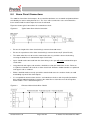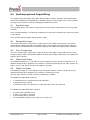
1
3300 NON-ADDRESSABLE
FIRE ALARM CONTROL PANEL
INSTALLATION, COMMISSIONING AND
MAINTENANCE MANUAL
Protec Fire Detection PLC, Protec House, Churchill Way, Nelson, Lancashire, BB9 6RT.
Telephone:
Fax:
Web:
Email:
+44 (0) 1282 717171
+44 (0) 1282 717273
www.protec.co.uk
[email protected]
Document Revision Details
Issue
0
Modification Detail
Document Creation
93-530-70 Issue 0
Author
NH
Page 2 of 44
Date
12/02/07
© Protec Fire Detection PLC 2007
Table of Contents
1.0
3300 SYSTEM OVERVIEW ..........................................................................................................5
2.0
IMPORTANT NOTES – PLEASE READ ......................................................................................6
3.0
ITEMS SUPPLIED WITH THE 3300 PANEL ................................................................................6
4.0
CABLING REQUIREMENTS ........................................................................................................7
4.1
4.2
Detector, Alarm and Auxiliary Wiring .....................................................................................7
Mains Wiring ...........................................................................................................................7
5.0
INSTALLATION PROCEDURE ....................................................................................................8
6.0
TESTING OF CABLING PRIOR TO CONNECTION ..................................................................11
7.0
DETECTOR CIRCUIT CONNECTIONS......................................................................................11
8.0
ALARM CIRCUIT CONNECTIONS ............................................................................................12
9.0
AUXILIARY INPUT AND OUTPUT WIRING ..............................................................................13
9.1
9.2
9.3
9.4
9.5
Keyswitch Input ....................................................................................................................13
Remote Alarm Input .............................................................................................................13
Class Change Input ..............................................................................................................13
Global Fault Output ..............................................................................................................13
Global Fire Output ................................................................................................................13
10.0
REPEAT PANEL WIRING ..........................................................................................................14
11.0
INTERNAL EXPANSION PORT .................................................................................................15
12.0
COMMISSIONING .......................................................................................................................16
12.1
12.2
12.3
13.0
Connecting the Mains ...........................................................................................................16
Installing and Connecting The Standby Batteries ................................................................17
Switching On ........................................................................................................................17
PROGRAMMING OVERVIEW ....................................................................................................18
13.1
13.2
Access Levels.......................................................................................................................18
Zone Programming Choices.................................................................................................19
14.0
PROGRAMMING DETAILS ........................................................................................................20
14.1
PROGRAMMING ZONE DISABLEMENTS ................................................................................20
14.2
14.3
14.4
14.5
14.6
14.7
Programming Alarm Disablements ..................................................................................21
Programming Zone Delays ................................................................................................22
Programming Zones into Test Mode ................................................................................23
Programming Coincidence Zones ....................................................................................24
Programming Non-Latching Zones ..................................................................................25
Programming Expansion Interface Node Information ....................................................26
15.0
OVERRIDING SYSTEM DELAYS ..............................................................................................27
16.0
DISABLING THE FIRE LINK INTERFACE ................................................................................28
17.0
DELAYING FIRE LINK ACTIVATIONS ......................................................................................29
18.0
PSU MONITORING TYPE SET-UP ............................................................................................30
93-530-70 Issue 0
Page 3 of 44
© Protec Fire Detection PLC 2007
19.0
PROGRAMMING END OF LINE TYPE ......................................................................................30
20.0
PROGRAMMING PULSING ALARMS .......................................................................................31
21.0
FAULT DIAGNOSIS FEATURES ...............................................................................................31
22.0
3300 SOFTWARE VERSION DISPLAY .....................................................................................32
23.0
DETECTOR ZONE FAULT DETAILS.........................................................................................33
24.0
ALARM FAULT DETAILS ..........................................................................................................34
25.0
SYSTEM FAULT DETAILS .........................................................................................................35
26.0
POWER SUPPLY FAULT DETAILS ..........................................................................................36
27.0
FAULT RECTIFICATION GUIDELINES .....................................................................................37
28.0
3300 TECHNICAL SPECIFICATION ..........................................................................................38
29.0
3300 FEATURES SPECIFICATION ...........................................................................................39
30.0
APPENDIX 1. ACCESSORIES AVAILABLE FOR THE 3300. ..................................................40
31.0
APPENDIX 2. 3300 SPARES LIST.............................................................................................41
32.0
APPENDIX 3. DECIMAL TO BINARY CONVERSION CHART .................................................42
33.0
APPENDIX 4. 3300 MAIN PCB DETAILS ..................................................................................43
34.0
APPENDIX 5. 3300 PROGRAMMING QUICK REFERENCE GUIDE .......................................44
93-530-70 Issue 0
Page 4 of 44
© Protec Fire Detection PLC 2007
1.0
3300 System Overview
The main features of the Protec 3300 Fire Alarm system are:
•
Four and eight detector zone models available.
•
Four monitored alarm circuits rated at 150mA each.
•
Common negative (allowing three wire operation).
•
Manual call point activation can override zone delays.
•
Re-sounding of outputs if a zone changes from automatic to manual activation.
•
Three auxiliary inputs, Keyswitch, Class Change and Remote Alarm.
•
Global Fire and Global Fault clean contact connections.
•
Monitored Auxiliary 24V output (Overload Protected, 100mA maximum).
•
Programmable capacitive or resistive detector circuit end of line monitoring.
•
Extensive range of engineering functions, accessed via a 5 digit code entry or key-switch
activation.
•
•
•
•
•
•
•
•
Delays to zones.
Disablement of zones.
Coincidence Operation.
testing of zones.
Non-latching zones.
Disablement of alarm circuits.
Disablement of fire link output.
Comprehensive fault diagnosis features.
•
Expansion outputs to drive one fire link interface and one eight way zonal mimic interface.
•
Repeat panel output to drive up to eight 3300 Repeat Panels, no extra driver board is required.
•
All interfaces supported as standard.
•
Low quiescent current of 15mA (24V dc supply, mains fail fault, no external equipment).
Note: Due to a policy of continuous improvement Protec Fire Detection PLC reserve the right to alter
the specification without prior notice.
93-530-70 Issue 0
Page 5 of 44
© Protec Fire Detection PLC 2007
2.0
Important Notes – PLEASE READ
•
THE FIRE ALARM PANEL AND ITS ASSOCIATED CONNECTIONS MUST BE INSTALLED,
COMMISSIONED AND MAINTAINED BY A SUITABLY SKILLED AND COMPETENT PERSON.
•
THIS EQUIPMENT MUST BE EARTHED.
•
THIS EQUIPMENT IS NOT GUARANTEED UNLESS INSTALLED AND COMMISSIONED IN
ACCORDANCE WITH CURRENT NATIONAL STANDARDS.
•
THIS EQUIPMENT HAS BEEN DESIGNED AND MANUFACTURED TO CONFORM WITH
THE REQUIREMENTS OF ALL APPLICABLE EU COUNCIL DIRECTIVES.
•
THIS MANUAL MUST BE THOROUGHLY READ AND UNDERSTOOD BEFORE
INSTALLATION AND COMMISSIONING OF THIS EQUIPMENT IS UNDERTAKEN.
3.0
Items Supplied with the 3300 panel
•
Installation, commissioning and maintenance manual.
•
User manual.
•
Mounting template.
•
Accessory pack, comprising:
•
•
•
•
•
•
•
8 x 100µF/22Ω detector circuit end of line units
4 x 10kΩ alarm circuit end of line units
1 x red battery lead
1 x black battery lead
1 x inter-battery connection lead
1 x 1A HRC power supply fuse
1 x 1.6A battery fuse
93-530-70 Issue 0
Page 6 of 44
(41-804-52)
(41-800-48)
(41-791-64)
(41-790-63)
(41-796-44)
(15-131-35)
(15-055-40)
© Protec Fire Detection PLC 2007
4.0
Cabling Requirements
4.1
Detector, Alarm and Auxiliary Wiring
All external wiring associated with the system must conform to the current I.E.E Regulations and
cabling must conform to the relevant BS specifications. ECA recommended Cable Separation for
Electromagnetic Compatibility in Buildings must be followed.
To comply with EMC regulations Protec recommends the use of screened cabling throughout the
installation. The screens must be securely connected to the screwed earthing studs provided inside
the 3300 enclosure.
Screened cables that are suitable for wiring are:
TM
TM
TM
MICC (Pyro ), Pirelli FP200 , FireTuff , or any other cable which complies with BS 6387
(categories C, W, Z).
Proper glanding of the cable is vital to the correct performance of the system.
4.2
Mains Wiring
The 3300 requires a mains supply exclusive to the panel that uses fixed three core wiring (between
2
2
0.75mm and 2.5mm ) which is fed from a double pole isolating fused spur, fused at 3A.
Unauthorised operation of the mains supply should not be allowed and the fused spur should be
labelled “FIRE ALARM: DO NOT SWITCH OFF”
93-530-70 Issue 0
Page 7 of 44
© Protec Fire Detection PLC 2007
5.0
Installation Procedure
The 3300 fire alarm panel circuit boards are housed in a plastic enclosure. When the front is removed
from the panel the circuit boards and the batteries are fully accessible. The panel can still be
controlled even though the front has been removed.
The panel can be surface or flush mounted.
The panel must be located internally in an area that is not subject to dampness, extremes of
temperature or physical abuse. The environmental limits are given in section 21.0
1)
Unpacking
After opening the box remove the installation template and spares pack from the packaging,
leaving the 3300 in the cardboard box for protection.
2)
Preparing the Mounting Position
Use the installation template in conjunction with a spirit level to mark out the fixing locations
for the panel. Drill and plug the mounting holes previously marked.
3)
Removal of the Door
Remove the 3300 unit from the packaging. Remove the two screw covers from the lower two
corners of the front door and unscrew the two front door fixing screws.
Swing the door upward from the bottom and lift away, see figure 5.0.
Put all removed parts in a safe, dry place.
Figure 5.0 – Removing the door from a 3300.
93-530-70 Issue 0
Page 8 of 44
© Protec Fire Detection PLC 2007
4)
Removal of the Main PCB.
NOTES ON ANTI-STATIC HANDLING OF THE PCBs
Before handling any of the circuit boards in the 3300 it is vital that any operatives
discharge themselves of any static charge that may have built up on them. This can be
done by momentarily touching a solid earth point (a non-painted part of a radiator, for
example).
Handle the PCBs by their sides and DO NOT touch the electronic components on them.
The PCB should be stored in a clean, dry place away from the place of work. Retain the
PCBs in a cardboard box for safety until they are required.
Disconnect the 3 way connector from the main PCB, taking care not to strain the connector or
the PCB. Leave the connector attached to the Power Supply PCB.
Unscrew and remove the two mounting screws on the main PCB. Carefully slide the Main
PCB upward (stage 1) and lift away from the plastic enclosure (stage 2). See figure 5.1.
Store all screws and PCBs in a safe, dry place.
Figure 5.1 – Removal of the 3300 Main PCB.
Stage 2
PCB fixing screw
Stage 1
PCB fixing screw
.
93-530-70 Issue 0
3 way power
connector
Page 9 of 44
© Protec Fire Detection PLC 2007
5)
Preparing and Fixing the Panel Back-box
The mains cable entry position should be kept away from other system cabling.
Carefully knock out the required cable entry positions and mount the enclosure at the position
prepared in (2) whilst feeding the cables into the enclosure.
6)
Refitting the Main PCB
Note: Before re-fitting the main PCB the mains power connections to the Power Supply
PCB should be connected. See section 12.0.
DO NOT SWITCH MAINS POWER ON AT THIS POINT !!
Route the battery cables through to the battery compartment using the channels provided.
Replace the Main PCB (a reversal of removal), ensuring it is pushed fully down to the bottom
edge of the panel. Secure with the two screws removed previously. Take care not to over
tighten the screws.
Re-connect the three way cable from the Power Supply to the Main PCB, do not use undue
pressure and ensure the cable is clipped into the locking ramp on the PCB header securely.
7)
Re-fitting the Door
Replace the plastic door by offering the top of the door up to the groove at the top of the
plastic back-box.
Swing the door down and ensure it pushes fully home into the back-box, without fouling the
rubber keypad or light-guides on the main PCB. See figure 5.3 for details.
Tighten the two screws in the lower two corners of the door, and replace the screw covers.
Figure 5.3 – Refitting the 3300 Door.
93-530-70 Issue 0
Page 10 of 44
© Protec Fire Detection PLC 2007
6.0
Testing of Cabling Prior to Connection
Before connecting any external cables to any field device (detectors, sounders, auxiliary inputs or
TM
outputs), or the 3300, tests must be carried out using a 500V dc insulation tester (Megger ). The
readings between each cable core, and each core and earth should be greater than 10MΩ.
Important Notes:
•
Equipment connected to the cabling during insulation tests could be damaged with the high
voltages used during the test.
•
Field devices and the 3300 MUST NOT be connected when high voltage insulation tests are being
performed on the cabling, the cabling must be completely discharged prior to connection to any
field devices or the 3300.
7.0
Detector Circuit Connections
Figure 7.0 shows a typical connection regime for a detector zone on the 3300.
Figure 7.0
Typical 3300 Detector Connection
•
Ensure the length of the zone wiring is no more than 500 metres.
•
Ensure the resistance of each conductor is no more than 15Ω.
•
Ensure the capacitance of the zone wiring is no more than 0.27µF (micro-Farads)
when no end of line capacitor is present.
•
The end of line unit (8k2 resistor or 100µF/22Ω network) must be placed at the very end of the
detector zone wiring, ensuring the whole zone is monitored.
•
Spurs should not be connected from the zone wiring as the spur will not be monitored for open
circuit faults.
•
To ensure compliance with EN54 Part 2 each detector base must include a series low voltage
drop diode, such that manual call points following a removed detector still function correctly.
Protec S3000 bases incorporate the diode as standard.
•
Manual call points must incorporate a series resistor to ensure the zone does not enter a short
circuit fault condition when the manual call point is activated. If the panel is to be able to
distinguish between automatic and manual zone activations the resistor value in the manual call
point must be 180Ω. In retrofit situations, values up to 560Ω can be used but ‘MCP fire’ may not
be given in all instances.
Protec 3300 manual call points incorporate the series 180Ω resistor as standard.
93-530-70 Issue 0
Page 11 of 44
© Protec Fire Detection PLC 2007
8.0
Alarm Circuit Connections
The 3300 has four alarm circuit outputs, all are rated for continuous use at 150mA and protected from
over-load by an auto resetting thermal ‘fuse’. The ‘fuse’ will reset when the cause of overload has
been removed and the alarm output has been de-activated.
Figure 8.0 shows typical connections for a 3300 alarm circuit.
Figure 8.0
Typical 3300 Alarm Circuit Connection.
•
Ensure the length of the alarm circuit wiring is no more than 500 metres.
•
Ensure the capacitance of the alarm circuit wiring is no more than 0.27µF (micro-Farads).
•
The 10kΩ end of line resistor must be connected at the very end of the alarm circuit wiring,
ensuring the whole line is monitored for open circuit faults.
•
Spurs should not be connected from the alarm wiring as the spur will not be monitored for open
circuit faults.
•
Only polarised and suppressed sounders should be used on the 3300 alarm circuits. Failure to
use polarised sounders will result in an alarm circuit fault. All Protec S3000 sounders are polarised
and suppressed as standard.
•
Efforts should be made to evenly spread the sounder load across the 4 alarm circuits, to avoid
overloading any one of the alarm outputs.
•
It is acceptable to connect alarm circuits 1 and 2 or alarm circuits 3 and 4 in parallel (to obtain a
drive rating of 300mA continuous), however the end of line resistor value must be changed to
4k7Ω 1/2W 5%. This is detailed in figure 8.1
Figure 8.1
Enhanced Alarm Circuit Drive Details
93-530-70 Issue 0
Page 12 of 44
© Protec Fire Detection PLC 2007
9.0
Auxiliary Input and Output Wiring
The auxiliary input connections (Keyswitch, Remote Alarm and Class Change) and auxiliary output
connections (Global Fault and Global Fire) should be wired in screened cable. The screen should be
securely connected to the screwed earthing post provided in the panel.
9.1
Keyswitch Input
The keyswitch input is active when a short circuit (less than 50Ω) is connected across the keyswitch
terminals.
In the standard 3300 this is an alternate method of accessing level 2 functions if the code entry feature
is not required.
The keyswitch wiring should be kept local to the 3300.
9.2
Remote Alarm Input
The remote alarm input is active when a short circuit (less than 50Ω) is placed across the remote
alarm terminals. When activated the 3300 will activate alarm outputs, fast intermittently sound the
internal buzzer and illuminate the ‘General Fire’ indicator. The Global Fire output is NOT activated.
9.3
Class Change Input
The class change input is active when a short circuit (less than 50Ω) is connected across the Class
Change terminals. When activated the 3300 will activate alarm outputs continuously. The Global Fire
output is NOT activated.
9.4
Global Fault Output
The Global Fault output is a set of Volt free relay changeover contacts (rated at 1A 24V dc max.) to
allow interfacing to other equipment. The contacts are normally activated (the N/C and C contacts are
high resistance) and will release when the 3300 has any fault.
9.5
Global Fire Output
The Global Fire output is a set of Volt free relay changeover contacts (rated at 1A 24V dc max.) to
allow interfacing to other equipment. The contacts are normally released
(the N/C and C contacts are low resistance) and operate as follows.
The Global Fire output WILL activate if
•
•
•
A standard zone has activated (manual or automatic)
A delayed zone has expired
A coincidence zone has expired, or a second coincidence zone has activated
The Global Fire output WILL NOT activate if
•
•
•
•
A remote alarm activation occurs
A zone in test mode is activated
A non-latching zone is activated
The Sound Alarms button is pressed in access level 2 or 3
93-530-70 Issue 0
Page 13 of 44
© Protec Fire Detection PLC 2007
10.0 Repeat Panel Wiring
The 3300 can drive up to eight 3300 Repeat Panels directly from its External Expansion Interface port.
No extra driver boards are required.
The external expansion port has four connections, present on a terminal block labelled
‘EXT EXP’ on the Main PCB. These are:
1. +24V (fused at 100mA, self resetting (when overload and power is removed), non-monitored)
2. 0V
3. Data 4. Data +
This port connects to all Repeat Panels and should be wired in screened cable to ensure compliance
with relevant EMC regulations. Figure 10.0 shows a typical installation.
Figure 10.0
Typical 3300 External Expansion Interface Installation.
To further
Repeat
Panels
93-530-70 Issue 0
Page 14 of 44
© Protec Fire Detection PLC 2007
11.0 Internal Expansion Port
The 3300 can accept various internal interfaces, these must be located within the 3300 panel
enclosure. The interfaces currently available are:
•
Fire Link Interface, a maximum of one per panel.
•
8 way Volt free contact zonal fire / fault mimic. A maximum of one per panel.
These interfaces connect using the 10 pin expansion port (J2) located at the middle left of the Main
PCB. If both the fire link and the 8 way mimic interfaces are used, the fire link must be connected to
the 3300 then the 8 way mimic to the fire link interface.
Consult the relevant interface installation sheet for further details.
93-530-70 Issue 0
Page 15 of 44
© Protec Fire Detection PLC 2007
12.0 Commissioning
12.1
Connecting the Mains
Important Note:
•
Pay particular attention that the earth cable is firmly connected to the earth terminal of the
power supply, and that the earth strap from the power supply PCB to the earth post is
sound.
Ensure the fused double pole isolator is in the ‘OFF’ position then connect the incoming mains cable
to the appropriate terminals on the power supply PCB (see figure 12.0).
Figure 12.0
Power Supply Terminal Details
93-530-70 Issue 0
Page 16 of 44
© Protec Fire Detection PLC 2007
12.2
Installing and Connecting The Standby Batteries
The panel is designed to house two 12V 3.3Ah Valve Regulated Sealed Lead Acid (SLA) batteries.
These fit into the left hand compartment of the 3300 and should be secured with the Tie Wraps
provided.
The two batteries must be connected in series, a connecting link is supplied for this purpose.
The batteries must then be connected to the Power Supply PCB using the wires provided, please
observe polarity when connecting.
Ensure all spade connectors are pushed fully home onto the battery terminals.
Figure 12.1 shows the location and connection details for the batteries.
Figure 12.1
12.3
Installation of 3300 Standby batteries (shown with 3300 lid removed)
Switching On
Switch the fused isolator to the ‘ON’ position. The ‘Supply Present’ indicator should illuminate on the
front of the panel and, assuming all other connections are correct and the end of line units are present
(and the correct value) , no other faults should be displayed.
The 3300 is now ready to be programmed.
93-530-70 Issue 0
Page 17 of 44
© Protec Fire Detection PLC 2007
13.0 Programming Overview
The 3300 has many programming features, making it extremely flexible. These can be accessed by
users at different authorisation levels. The programming features and authorisation levels are detailed
below.
13.1
Access Levels
Access Level 1 (User code not entered)
The panel’s front panel display indicators are visible, providing a clear status of the 3300 at that time.
The functions that may be performed at access level 1 are:
•
Muting of the panel’s internal buzzer.
•
Entry of the 5 digit user code to access level 2 functions.
Access Level 2 (User code entered)
Only authorised users are permitted access to level 2 functions, these are:
•
Silencing an alarm condition.
•
Sounding the alarms.
•
Resetting the panel after an alarm activation.
•
Testing the front panel indications, and internal buzzer.
•
Programming a zone into test mode (only one test zone at once is permitted).
•
Disablement of detector circuits.
•
Disablement of alarm circuits.
•
Disablement of any programmed delays (detector and fire link).
•
Disablement of the fire link interface (if fitted).
93-530-70 Issue 0
Page 18 of 44
© Protec Fire Detection PLC 2007
Access Level 3 (Engineer Controls)
Only engineers are permitted access to level 3 functions, these are:
•
All level 2 functions, plus
•
The setting of zone delay times.
•
The programming of delayed zones.
•
The programming of coincidence zones.
•
The programming of non-latching zones.
•
The programming of test zones (one, or more zones may be programmed).
•
The programming of expansion interface data.
•
Fault diagnosis features.
•
Programming the end of line type.
•
Programming the power supply type.
13.2
Zone Programming Choices
Each zone of the 3300 may be programmed in the following manner.
•
Non-latching mode.
•
Coincidence mode.
•
Delay mode.
•
Test mode.
Please not that a zone can only be programmed with one of the choices (ie. a zone cannot be set-up
as non-latching and delay) the last programmed choice will be accepted by the 3300.
NOTE: Test mode overrides all other programming.
93-530-70 Issue 0
Page 19 of 44
© Protec Fire Detection PLC 2007
14.0 Programming Details
In general the front panel buttons have the following alternate functions when the 3300 is in
programming mode.
When Access Level 3 programming functions are being performed the ‘Supply Present’ indicator will
flash.
Button 1
Button 2
Button 3
Button 4
Toggle.
Scroll.
Accept.
Back / Exit / Program.
14.1 Programming Zone Disablements
The 3300 can have one, or more, of its detector zones disabled. When a zone is disabled faults and
activations from that zone are inhibited.
1. From access level 1 enter your 5 digit user code 1 3 4 4 2 or turn the key-switch (depending on
the model purchased).
2. The ‘level 2 Accessed’ indicator will illuminate.
3. Press button 2 once – The ‘General Disablement’ indicator will illuminate steady to show the zone
disablement option is selected (the normal front panel display is temporarily replaced with the
programming display). Any current disablements will be displayed on row 1 of the display. Accept
the option by pressing button 3.
4. The ‘General Disablement’ indicator will flash, showing this option has been accepted.
5. Highlight the zone to be disabled by repeatedly pressing button 2.
6. Press button 1 to show that it is to be disabled / not disabled. The relevant row 1 indicator will be
illuminated if the zone is disabled.
7. Follow the procedure above until all zones that are to be disabled have their row 1 indicators
illuminated.
8. Press button 3 to return to the programming selection menu.
9. Press button 4 to accept and program the disablement set-up and return to access level 2.
10. The yellow ‘General Disablement’ indicator will be illuminated steady, as will the row 2
disablement indicator for the relevant zone(s).
93-530-70 Issue 0
Page 20 of 44
© Protec Fire Detection PLC 2007
14.2
Programming Alarm Disablements
The 3300 can have alarm circuits 1 and 2 and/or alarm circuits 3 and 4 disabled. When an alarm
circuit is disabled faults and activations on that circuit are inhibited.
1. From access level 1 enter your 5 digit user code 1 3 4 4 2 or turn the key-switch (depending on
the model purchased).
2. The ‘Level 2 Accessed’ indicator will illuminate.
3. Using button 2 scroll to the ‘Alarm Outputs’ indication. Any current alarm disablements will be
displayed on row 1 of the display. Accept this option by pressing button 3.
4. The ‘Alarm Outputs’ indicator will flash, showing this option has been accepted.
5. Highlight the alarm circuit pair to be disabled by pressing button 2
•
Highlight zone 1 indicator if alarm circuits 1 and 2 are to be disabled.
•
Highlight zone 2 indicator if alarm circuits 3 and 4 are to be disabled.
Note: Zone 3 and zone 4 indicators can also be selected in this option. See sections 15.0
and 16.0 for details
6. Press button 1 to show that it is to be disabled / not disabled. If the alarm circuit is disabled the
relevant row 1 indicator will be illuminated.
7. Press button 3 to return to the selection menu.
8. Press button 4 to accept and program the disablement set-up and return to access level 2.
9. The yellow ‘General Disablement’ indicator will be illuminated steady, as will the yellow ‘Alarm
Outputs’ indicator.
93-530-70 Issue 0
Page 21 of 44
© Protec Fire Detection PLC 2007
14.3
Programming Zone Delays
The 3300 can have a delay programmed on one or more of its detector zones. When a zone delay is
programmed, a fixed time delay ( 0 to 10 minutes ) is given from activation of that zone to activation of
the alarm outputs / global fire relay and fire link output ( if fitted ). However a manual call point
activation on a delayed zone will override the delay.
The delay time is set up by adjusting a potentiometer ( VR1 ) on centre of the Main PCB, See
appendix 4 for the location of the potentiometer.
If the ‘Silence Alarms’ button is pressed while a delay is running, the alarm outputs will not be
activated when the delay expires. The global fire contacts, however, will still be activated.
Note:
•
The delay time applies to ALL zones programmed with delays.
•
The exact delay time should be verified during commissioning, and noted on the system set-up
record in the 3300 user manual.
The procedure for programming a zone delay is given below.
1. From access level 1 enter the 5 digit engineer code 1 3 4 2 4. The ‘Supply Present’ indicator
will flash indicating level 3 has been accessed and all programming features are available.
2. Scroll to the ‘Output Delay’ indicator by repeatedly pressing button 2. Any currently programmed
zone delays will be displayed on row 1 of the display. Accept the option by pressing button 3.
3. The ‘Output Delay’ indicator will flash, to indicate this option has been accepted.
4. Scroll to the detector zone to be delayed by pressing button 2.
5. Press button 1 to set delayed / not-delayed for that zone. The row 1 indicator will be illuminated
when the zone is delayed.
6. Press button 3 to return to the selection menu.
7. Press button 4 to accept and program the delayed zones and return to access level 2.
The yellow ‘Output Delay’ indicator will be illuminated steady, showing that at least one zone (or the
fire link interface, if fitted) has a delay programmed.
93-530-70 Issue 0
Page 22 of 44
© Protec Fire Detection PLC 2007
14.4
Programming Zones into Test Mode
The 3300 can have one or more of its detector zones programmed into test mode. When a zone is
programmed into test mode any activation on that zone will cause the alarm outputs to activate for 4
seconds, after which the 3300 will reset. This feature is used to enable rapid testing of detectors on
zones without the need to return to the panel to reset it after each activation.
Note:
•
If any non-test zones are active the 3300 will not reset.
•
Zones activated in test mode DO NOT operate the ‘Fire Link’ and DO NOT activate
the Global Fire Contacts.
The procedure for programming a zone into test is given below.
1. From access level 1 enter the 5 digit engineer code 1 3 4 2 4. The ‘Supply Present’ indicator
will flash indicating level 3 has been accessed and all programming features are available.
2. Scroll to the ‘General Test’ indicator by pressing button 2. Any zones currently programmed into
test mode will be displayed on row 1 of the display. Accept the option by pressing button 3.
3. The ‘General Test’ indicator will flash, to indicate this option has been accepted.
4. Scroll to the detector zone to be put into test mode by pressing button 2.
5. Press button 1 to set / un-set that zone into test mode. The relevant row 1 indicator will be
illuminated when the zone is in test mode.
6. Press button 3 to return to the selection menu.
7. Press button 4 to accept and program the test set-up and return to access level 2.
The yellow ‘General Test’ indicator will be illuminated steady, showing that at least one zone has been
programmed into test mode. Any zones programmed into test mode will have their test indicator
illuminated steady on row 2 of the display.
Important Note:
•
Ensure all zones are removed from test mode when testing of the system is complete.
93-530-70 Issue 0
Page 23 of 44
© Protec Fire Detection PLC 2007
14.5
Programming Coincidence Zones
With the 3300 it is possible to program two, or more zones as coincidence zones. This mode is useful
on sites where the consequence of a false alarm is onerous (for example if the panel is connected to
an extinguishing system).
If only one coincidence zone activates the panel will flash the relevant zone indicator, fast
intermittently sound the internal sounder and wait for one of the following to occur.
•
A second coincidence zone to activate.
•
An in built 2 minute time out on the first coincidence zone to expire.
•
A manual call point activation on any non-disabled zone to occur.
The 3300 will then activate its alarm outputs, global fire contacts and fire link interface (if fitted).
If the cause of the first activation is found to be legitimate the ‘Sound Alarms’ button can be pressed at
access level 2 or 3 to activate the alarm outputs. If the cause is found to be a false alarm the ‘Silence
Alarms’ then ‘Reset Panel’ buttons can be pressed.
The procedure for programming a zone into a coincidence group is given below.
1. From access level 1 enter the 5 digit engineer code 1 3 4 2 4. The ‘Supply Present’ indicator
will flash indicating level 3 has been accessed and all programming features are available.
2. Scroll to the ‘Level 2 Accessed’ indicator by repeatedly pressing button 2. Any zones currently
programmed as coincidence will be displayed on row 1 of the display. Accept the option by
pressing button 3.
3. The ‘Level 2 Accessed’ indicator will flash to indicate this option has been accepted.
4. Scroll to the detector zone to be set as coincidence by pressing button 2.
5. Press button 1 to set / un-set that zone as a coincidence zone (the relevant row 1 indicator will be
illuminated when the zone is set as coincidence).
6. Program any other zones required into coincidence (by following steps 5 and 6).
7. Press button 3 to return to the selection menu.
8. Press button 4 to accept and program the coincidence set-up and return to access level 2.
93-530-70 Issue 0
Page 24 of 44
© Protec Fire Detection PLC 2007
14.6
Programming Non-Latching Zones
With the 3300 it is possible to program one, or more of the detector zones to operate as non-latching.
In this mode the zone activates as normal, but when the cause of the activation is removed the 3300
will reset.
The Global Fire contacts and fire link (if fitted) do not operate on a non-latching zone activation.
This feature is of use when connecting fire alarm systems together, and ensures a latch up situation
cannot occur where each panel triggers the other due to latched zone activations.
The procedure for programming a zone as non-latching is given below.
1. From access level 1 enter the 5 digit engineer code 1 3 4 2 4. The ‘Supply Present’ indicator
will flash indicating level 3 has been accessed and all programming features are available.
2. Scroll to the ‘Fire link Operated’ indicator by repeatedly pressing button 2. Any zones currently
programmed as non-latching will be displayed on row 1 of the display. Accept the option by
pressing button 3.
3. The ‘Fire Link Operated’ indicator will flash to indicate this option has been accepted.
4. Scroll to the detector zone to be programmed as non-latching by pressing button 2.
5. Press button 1 to set / un-set that zone as non-latching (the relevant row 1 indicator will be
illuminated when the zone is non-latching).
6. Press button 3 to return to the selection menu.
7. Press button 4 to accept and program the non-latching set-up and return to access level 2.
93-530-70 Issue 0
Page 25 of 44
© Protec Fire Detection PLC 2007
14.7
Programming Expansion Interface Node Information
The 3300 can accept interfaces on its expansion ports. The 3300 must be programmed with the
number of nodes to expect on its expansion ports, both internal and external.
The number of nodes is expressed in binary, using a 5 bit code. Please note that the 3 remaining bits
(indicated on zones 1, 2 and 3) are reserved for future features and should be left clear.
The procedure for programming expansion information is as follows:
1. From access level 1 enter the 5 digit engineer code 1 3 4 2 4. The ‘Supply Present’ indicator
will flash indicating level 3 has been accessed and all programming features are available.
2. Scroll to the ‘Fire link’ indicator (within the disablements section) by repeatedly pressing button 2.
Any node information currently programmed will be displayed on row 1 of the display. Accept the
option by pressing button 3.
3. The ‘Fire Link ’ indicator will flash to indicate this option has been accepted.
4. Using button 2 and button 1 enter the number of system nodes present in a binary format. The
zone 8 indicator is the least significant bit of the number and the zone 4 indicator is the most
significant bit.
Please consult Appendix 3 for clarification of decimal to binary conversion.
Note: The number of nodes must include all nodes on the external expansion port and any nodes
on the internal expansion port. For example if the 3300 has two repeat panels on its external
expansion port and one fire link Interface on its internal expansion port the total number of nodes
entered would be three.
5. Press button 3 to return to the selection menu.
6. Press button 4 to accept and program the expansion set-up and return to access level 2.
Figure 14.1
Example of programming 5 nodes into the 3300.
93-530-70 Issue 0
Page 26 of 44
© Protec Fire Detection PLC 2007
15.0 Overriding System Delays
It is possible for the authorised user (at access Level 2 or 3) to override any delays (zonal or fire link)
that may have been set up at access level 3. The procedure to do this is as follows.
1. From access level 1 enter your 5 digit user code 1 3 4 4 2 or turn the key-switch (depending on
the model purchased).
2. The ‘Level 2 Accessed’ indicator will illuminate.
3. Using button 2 scroll to the ‘Alarm Outputs’ indication. Any current setting in this option will be
displayed on row 1 of the display, on zone 3. Accept this option by pressing button 3.
4. The ‘Alarm Outputs’ indicator will flash, showing this option has been accepted.
5. Select the delay override option by pressing button 2 until the row 2 indicator for zone 3 is
illuminated.
6. Press button 1 to show that delays are no be overridden / not overridden. The row 1 zone 3
indicator will be illuminated if delays are overridden.
7. Press button 3 to return to the selection menu.
8. Press button 4 to accept and program the set-up and return to access level 2.
9. The ‘Output Delay’ indicator will be extinguished. All delays (zonal and fire link) are now
overridden.
93-530-70 Issue 0
Page 27 of 44
© Protec Fire Detection PLC 2007
16.0 Disabling The Fire Link Interface
It is possible for the authorised user (at access Level 2 or 3) to disable the Fire Link interface (if fitted).
Disabling the interface inhibits Fire Link faults and activations.
1. From access level 1 enter the 5 digit engineer code 1 3 4 2 4. The ‘Supply Present’ indicator
will flash indicating level 3 has been accessed and all programming features are available.
2. Using button 2 scroll to the ‘Alarm Outputs’ indication. Any current settings in this option will be
displayed on row 1 of the display, on zone 4. Accept this option by pressing button 3.
3. The ‘Alarm Outputs’ indicator will flash, showing this option has been accepted.
4. Select the ‘Disable Fire Link’ option by pressing button 2 until the row 2 indicator for zone 4 is
llluminated
5. Press button 1 to show that the fire link is to be disabled / not disabled. The row 1 zone 4 indicator
will be illuminated if the fire link is disabled.
6. Press button 3 to return to the selection menu.
7. Press button 4 to accept and program the set-up and return to access level 2.
8. The ‘Fire Link’ and ‘General Disablement’ indicators will be illuminated.
93-530-70 Issue 0
Page 28 of 44
© Protec Fire Detection PLC 2007
17.0 Delaying Fire Link Activations
It is possible for an engineer (at access Level 3) to allow a delay time before the Fire Link interface (if
fitted) activates.
1. From access level 1 enter the 5 digit engineer code 1 3 4 2 4. The ‘Supply Present’ indicator
will flash indicating level 3 has been accessed and all programming features are available.
2. Using button 2 scroll to the ‘Alarm Outputs’ indication. Any current settings in this option will be
displayed on row 1 of the display, on zone 5. Accept this option by pressing button 3.
3. The ‘Alarm Outputs’ indicator will flash, showing this option has been accepted.
4. Select the ‘Delay Fire Link’ option by pressing button 2 until the row 2 indicator for zone 5 is
illuminated.
5. Press button 1 to show that the Fire Link is to be delayed / not delayed. The row 1 zone 5 indicator
will be illuminated if fire link activations are delayed.
6. Press button 3 to return to the selection menu.
7. Press button 4 to accept and program the set-up and return to access level 2.
8. The ‘Output Delay’ indicator will be illuminated, showing that the system has a delay programmed.
Note: The Fire Link delay time is set up locally on the Fire Link interface. Please consult the
installation sheet for that product for further details.
93-530-70 Issue 0
Page 29 of 44
© Protec Fire Detection PLC 2007
18.0 PSU Monitoring Type Set-up
It is possible for an engineer (at access Level 3) to alter the Power Supply Monitoring type.
The default choice allows monitoring of the internal switchmode charger, the alternative choice allows
monitoring of the 3300 Dual Supply Interface (fitted when an external charger is used).
1. From access level 1 enter your 5 digit engineer code 1 3 4 2 4. The ‘Supply Present’ indicator
will flash, indicating level 3 has been accessed and all programming features are available.
2. Using button 2 scroll to the ‘Alarm Outputs’ indication. Any current settings in this option will be
displayed on row 1 of the display, on zone 6. Accept this option by pressing button 3.
3. The ‘Alarm Outputs’ indicator will flash, showing this option has been accepted.
4. Select the ‘PSU monitoring’ option by pressing button 2 until the row 2 indicator for zone 6 is
illuminated.
5. Press button 1 to select either Internal Charger monitoring (row 1 zone 6 not illuminated), or Dual
Supply Interface (row 1 zone 6 illuminated).
6. Press button 3 to return to the selection menu.
7. Press button 4 to accept and program the set-up and return to access level 2.
19.0 Programming End of Line Type
The 3300 end of line monitoring type is programmable. The standard type of monitoring is capacitive
(100µF & 22Ω). The alternate type of monitoring is resistive (8k2Ω +/-5%) and is used to allow the
3300 to be interfaced to existing installations.
1. From access level 1 enter your 5 digit engineer code 1 3 4 2 4. The ‘Supply Present’ indicator
will flash, indicating level 3 has been accessed and all programming features are available.
2. Using button 2 scroll to the ‘Alarm Outputs’ indication. Any current settings in this option will be
displayed on row 1 of the display, on zone 7. Accept this option by pressing button 3.
3. The ‘Alarm Outputs’ indicator will flash, showing this option has been accepted.
4. Select the ‘EOL selection’ option by pressing button 2 until the row 2 indicator for zone 7 is
illuminated.
5. Press button 1 to select either capacitive monitoring (row 1 zone 7 not illuminated), or resistive
monitoring (row 1 zone 7 illuminated).
6. Press button 3 to return to the selection menu.
7. Press button 4 to accept and program the set-up and return to access level 2.
93-530-70 Issue 0
Page 30 of 44
© Protec Fire Detection PLC 2007
20.0 Programming Pulsing Alarms
The alarm circuits 3 and 4 can be programmed to pulse (0.5s on / 0.5s off) when a zone delay is
expiring.
1. From access level 1 enter your 5 digit engineer code 1 3 4 2 4. The ‘Supply Present’ indicator
will flash, indicating level 3 has been accessed and all programming features are available.
2. Using button 2 scroll to the ‘Alarm Outputs’ indication. Any current settings in this option will be
displayed on row 1 of the display, on zone 8. Accept this option by pressing button 3.
3. The ‘Alarm Outputs’ indicator will flash, showing this option has been accepted.
4. Select the ‘Pulsing Alarms’ option by pressing button 2 until the row 2 indicator for zone 8 is
illuminated.
5. Press button 1 to select either non pulsing alarms (row 1 zone 8 not illuminated), or pulsing alarms
(row 1 zone 8 illuminated).
6. Press button 3 to return to the selection menu.
7. Press button 4 to accept and program the set-up and return to access level 2.
21.0 Fault Diagnosis Features
The 3300 incorporates comprehensive fault diagnosis features, designed to aid the service engineer in
locating faults on a 3300 system.
The fault diagnosis menu is reached by:
1. From access level 1 enter your 5 digit engineer code 1 3 4 2 4. The ‘Supply Present’ indicator
will flash, indicating level 3 has been accessed and all programming features are available.
2. Press button 3 to enter the fault diagnosis menu.
2. Using button 2 scroll through the various fault menus, each time a fault is selected a code will be
displayed on rows 1 and 2 of the display. Using the following sections the code can be decoded
and appropriate action taken.
3. Return to access level 2 by pressing button 4.
4. Return to access level 1 by pressing button 4 again.
93-530-70 Issue 0
Page 31 of 44
© Protec Fire Detection PLC 2007
22.0 3300 Software Version Display
The 3300 will display its software versions when the ‘Alarms Silenced’ indicator is illuminated in fault
diagnosis mode.
Display row 1 will display the main software version.
Display row 2 will display the special software version (if applicable).
The software versions are displayed in 8 bit binary with the least significant bit being indicated at zone
8 and the Most significant bit being indicated at zone 1. Please consult the binary to decimal converter
given in appendix 3 for clarification. An example of software version 10 and special version 5 is given
in figure 22.0.
Figure 22.0.
Example of Software Version Display.
93-530-70 Issue 0
Page 32 of 44
© Protec Fire Detection PLC 2007
23.0 Detector Zone Fault Details
The 3300 will display the fault status of the detector zones if the ‘General Fault’ indicator is illuminated
in fault diagnosis mode.
•
Display row 1 shows any open circuit zone faults.
•
Display row 2 shows any short circuit zone faults.
The example in figure 23.0 shows Zone 2 as having an open circuit fault and Zone 7 as having a
short circuit fault.
Figure 23.0
Example of a Detector Zone Fault Display.
93-530-70 Issue 0
Page 33 of 44
© Protec Fire Detection PLC 2007
24.0 Alarm Fault Details
The 3300 will display the fault status of its alarm outputs if the ‘Alarm Fault’ indicator is illuminated in
the fault diagnosis mode.
Display row 1 shows any open circuit faults.
•
Zones 1 & 2 will be illuminated when alarm circuits 1 or 2 have an open circuit fault.
•
Zones 3 & 4 will be illuminated when alarm circuits 3 or 4 have an open circuit fault.
Display row 2 shows any short circuit faults.
•
Zones 1 & 2 will be illuminated when alarm circuits 1 or 2 have a short circuit fault.
•
Zones 3 & 4 will be illuminated when alarm circuits 3 or 4 have a short circuit fault.
Figure 24.0 shows alarm circuits 1 or 2 having an open circuit fault condition and alarm circuits 3 or 4
having a short circuit fault condition.
Figure 24.0
Example of an alarm fault display.
93-530-70 Issue 0
Page 34 of 44
© Protec Fire Detection PLC 2007
25.0 System Fault Details
The 3300 will display the system fault status of the system if the ‘System Fault’ indicator is illuminated
when in the fault diagnosis menu.
Display row 1 gives details of current system faults, as detailed in figure 25.0
Figure 25.0
Details of System Fault Information.
Zone 1 indicator will be illuminated if an EEPROM checksum error has been detected.
Zone 2 indicator will be illuminated if a PROGRAM checksum error has been detected.
Zone 3 indicator will be illuminated if a WATCHDOG fault has been detected.
Zone 4 indicator will be illuminated if a SW ERROR fault has been detected.
Zone 5 indicator will be illuminated if an external or internal interface fault (missing / faulty node) has
been detected.
Please see section 27.0 for guidelines on how to rectify the faults.
93-530-70 Issue 0
Page 35 of 44
© Protec Fire Detection PLC 2007
26.0 Power Supply Fault Details
The 3300 will display any current power supply faults if the ‘Power Supply Fault’ indicator is
illuminated when in fault diagnosis mode.
Display row 1 gives details of the power supply fault, as detailed in figure 26.0
Figure 26.0
Details of Power Supply Fault Information.
Zone 1 indicator will be illuminated if the battery charge voltage is too high.
Zone 2 indicator will be illuminated if the battery charge voltage is loo low.
Zone 3 indicator will be illuminated if the battery is faulty, or has been removed.
Zone 4 indicator will be illuminated if the battery has reached its deep discharge level.
Zone 5 indicator will be illuminated if the mains has failed to the charger.
All the zone indications will be illuminated if the communication channel to the power supply has
failed.
Please see section 27.0 for guidelines on how to rectify the faults.
93-530-70 Issue 0
Page 36 of 44
© Protec Fire Detection PLC 2007
27.0 Fault Rectification Guidelines
Fault
Detector Circuit Open / Short
Circuit
Suggested Action
Disconnect the faulty zone and re-connect the end of line unit (resistive or
capacitive) directly at the 3300 zone terminals. If the zone fault clears the zone
wiring and detector base connections should be thoroughly investigated, and
any faults rectified. In particular check that all detectors are connected properly
into their bases.
If the fault remains check the correct end of line monitoring is programmed,
ensure it is set-up for the type of end of line monitoring being used (resistive or
capacitive). If the fault still remains either the end of line, or the Main PCB is
faulty.
EEPROM checksum fault
A checksum error has been detected in the site data stored in EEPROM. Enter
access level 2 and press ‘Silence Alarms’ then ‘Reset Panel’ to clear the fault. If
it re-appears within 10 minutes the Main PCB is suspect and should be
replaced.
PROGRAM checksum fault
A checksum error has been detected in the system program memory. Enter
access level 2 and press ‘Silence Alarms’ then ‘Reset Panel’ to clear the fault. If
it re-appears within 3 minutes the Main PCB is suspect and should be replaced.
WATCHDOG fault
A watchdog time-out has been detected by the program. Enter access level 2
and press ‘Silence Alarms’ then ‘Reset Panel’ to clear the fault. If the fault
persists the Main PCB is suspect and should be replaced.
SW_ERROR fault
An expected software function has not been carried out. Enter access level 2
and press ‘Silence Alarms’ then ‘Reset Panel’ to clear the fault. If the fault
persists the Main PCB is suspect and should be replaced.
Expansion Node fault
A node has been detected as missing or faulty on either the internal or external
expansion ports. Check all nodes to ensure their address switches are all
correct (set from address 1 onwards). If so determine which node is missing or
faulty, then rectify the problem on that node.
Alarm Open / Short Circuit Fault
Disconnect the faulty alarm circuit and re-connect the end of line unit directly at
the 3300 alarm terminals. If the alarm fault clears the alarm wiring and sounder
connections should be thoroughly investigated, and any faults rectified. In
particular ensure all sounders are polarity protected and suppressed.
If the fault remains the Main PCB is suspect and should be replaced.
Power Supply Fault
If the mains has failed first verify the mains supply to the panel is correct. If it is
check the mains fuse (FS2 on the power supply PCB) and replace it if it has
ruptured (1A HRC 20mm).
If a battery over-voltage condition exists the power supply PCB is suspect and
should be replaced.
If a battery under-voltage condition exists replace the batteries with a new fully
charged set. If the fault does not clear within two hours the power supply PCB
is suspect and should be replaced
If a battery faulty condition exists verify the connections to the batteries are
sound. If the connections are sound and the fault persists replace the batteries
with two new, fully charged ones and leave to charge for two hours.
93-530-70 Issue 0
Page 37 of 44
© Protec Fire Detection PLC 2007
28.0 3300 Technical Specification
Power Supply Mains
230V AC. Nominal (+/-10%).
Integral Charger
1A switch mode, temperature compensated, 250mA battery charge current.
Batteries monitored for disconnection, failure and deep discharge.
Auxiliary 24V output
24V dc, 100mA max, monitored for fuse failure. (fuse self resetting)
Maximum Battery Size
2 x 12V 3.3Ah.
Mains Fuse
1A HRC ceramic 20mm.
Battery Fuse
1.6A F 20mm.
Working Voltage
20V to 30V dc.
Current Consumption
15mA (24V dc. Supply, not in alarm, mains failed, buzzer slow beeping,
General and PSU fault light illuminated) + detector load.
Number of Detector Zones
4 or 8 depending on the model purchased.
Maximum Zone Cable Length
500 Metres
Maximum Zone Cable Capacitance
0.27µF (measured with no end of line fitted)
Maximum Zone Cable Resistance
15Ω per conductor.
Detector Circuit EOL Values
Resistive (8.2kΩ) or capacitive (100µF/22Ω).
Maximum Quiescent Zone Load
1.5mA per zone.
Maximum Number of Detectors
20 per zone (smoke or heat)
Maximum Number of Devices
32 (Manual Call Points and Detectors) per zone
Manual Call Point Series Resistor Value
180Ω 5%
Number of Alarm Circuits
4 (open and short circuit monitored).
Alarm Circuit End Of Line Value
10kΩ 1/4W 5%.
Maximum Alarm Load
150mA from each alarm output. Sounders must be polarised and
suppressed.
Class Change Input
Activates alarm outputs when connected to 0V.
Remote Alarm Input
Activates alarm outputs, internal buzzer and general fire indicator when
connected to 0V.
Global Fault Contacts
Rated at 24V dc 1 Amp.maximum
Global Fire Contacts
Rated at 24V dc 1 Amp. maximum
Expansion Port Communications
2 wire Communication + 2 wire Power.
Temperature Range
0 to 40 degrees C.
Humidity Limit
85% Non-Condensing.
Environment
Meets IP30 if mounted in a dry position that does not exceed the temperature
and humidity limits given.
Mounting
3 or 4 points surface mount.
93-530-70 Issue 0
Page 38 of 44
© Protec Fire Detection PLC 2007
29.0 3300 Features Specification
Delay to Zone Activation
0 to 10 minutes programmable (applies to all zones programmed for delay)
Coincidence on Zones
2 or more zones programmable (2 or more zones must activate together to trigger
panel). A default time-out is given if only one coincidence zone activates. The time-out
is the same as the one programmed for zone delays.
A manual activation on a coincidence zone will also activate the panel.
Non-latching Zones
1 or more zones may be programmed non-latching. Panel resets when cause of the fire
is cleared. Global fire and fire link outputs (if fitted) do not activate.
Zone Disablements
1 or more zones can be disabled to prevent faults and activations
Alarm Disablements
Alarm Circuits 1 / 2 and 3 / 4 can be disabled to prevent faults and activations.
Fire Link Disablement
The fire link PCB (if fitted) can be disabled to prevent faults and activations.
Fire Link Delay
The fire link PCB (if fitted) can be set to have an activation delay.
Zonal Test
1 or more zones. When triggered operates alarm outputs for 4 seconds, then resets
panel (assuming no other non-test zone are activated)
Ability to Distinguish Between
Manual or Automatic Zone Activation
When the Manual Call Point Incorporates a 180Ω resistor.
Ability to re-activate a silenced zone
by a manual Call Point Activation
A zone activated by an automatic detector, then silenced, can be
re-triggered by a Manual Call Point Activation.
Ability to Accept Repeat Panels
Up to eight 3300 Repeat Panels may be connected on the external expansion port to
provide full main panel display mimic and allow access to all level 2 functions from
remote parts of a site. No extra drivers are required to run the repeat panels.
Ability to Accept a Fire Link
Interface
One Fire Link Interface may be connected to the internal
expansion port.
Peripheral Interfaces Available
8 way zonal fire / fault Volt free contact Interface, connects to the internal
expansion port.
Fault Diagnosis
Comprehensive fault diagnosis features can be accessed at level 3.
These give further details of PSU faults, Zone Faults, Alarm Faults, System
Faults, Fire Link faults.
Note: Due to a policy of continuous improvement Protec Fire Detection PLC reserve the right to alter the specification without
prior notice.
93-530-70 Issue 0
Page 39 of 44
© Protec Fire Detection PLC 2007
30.0 Appendix 1. Accessories Available for the 3300.
The following accessories are available for the 3300 control panel.
1.
S3000 Optical Smoke Detector (3000/OP)
A high performance optical smoke detector.
2.
S3000 Optical Heat Detector (3000/OPHT)
A high performance thermally enhanced optical smoke detector, designed to give higher
immunity against false alarms.
3.
S3000 Heat Detectors (3000/TEMP56, TEMP64 and TEMP84)
Three high performance heat detectors.
The TEMP56 provides anticipatory (rate of rise) action with a final set-point of
56 degrees C.
The TEMP64 is a fixed set-point unit, with a trip level of 64 degrees C.
The TEMP84 is a high temperature device with a fixed trip level of 84 degrees C.
4.
S3000 Base (3000/BASE)
A base with in-built low Voltage drop diode for use with all the detector products
above.
mentioned
5.
3300 Manual call point (3100/BGK)
A Manual Call Point Unit with built in 180Ω resistor.
6.
S3000 Sounder Base (3000/SB)
A high output 24V powered sounder base that accepts a detector.
7.
S3000 System Sounder (3000/SSR2)
A high output, low current, 24V powered system sounder.
8.
S3000 System Sounder Beacon (3000/SSR2/LED/R)
A high output, low current, 24V powered system sounder with integral LED beacon array.
9.
3300 4 Wire Repeat Panel (3300/RP)
This unit is designed to be connected to the 3300 external expansion port, up to eight repeat
panels may be connected. Each repeat panel must be configured with its own node number
by a DIL switch on the PCB.
10.
3300 Fire Link Interface (3300/FL)
This unit is designed to be connected to the 3300 internal expansion port. One fire link PCB
may be fitted into a 3300 control panel. The 3300 Fire Link Interface gives a monitored output
to a fire station call unit. The interface must be allocated a unique node number on the 3300
expansion system, using the on board DIL switch on the fire link PCB.
The 3300 fire link interface must be used in conjunction with a 3300 Fire Link End Of Line unit
(3100/FLEOL)
93-530-70 Issue 0
Page 40 of 44
© Protec Fire Detection PLC 2007
31.0 Appendix 2.
3300 Spares List
Description
Protec Stock Code
Capacitive end of line module
41-804-52
10kΩ alarm end of line resistor
41-800-48
1.6A F battery fuse
15-055-40
1A HRC mains fuse
15-131-35
3300 accessory pack (all of above)
62-602-55
Red battery lead
41-791-64
Black battery lead
41-790-63
Battery inter-connection lead
41-796-44
3300 User Manual
N93-531-79
93-530-70 Issue 0
Page 41 of 44
© Protec Fire Detection PLC 2007
32.0 Appendix 3.
Decimal to Binary Conversion Chart
0
00000000
49
00110001
98
01100010
147 10010011
196 11000100
1
00000001
50
00110010
99
01100011
148 10010100
197 11000101
2
00000010
51
00110011
100 01100100
149 10010101
198 11000110
3
00000011
52
00110100
101 01100101
150 10010110
199 11000111
4
00000100
53
00110101
102 01100110
151 10010111
200 11001000
5
00000101
54
00110110
103 01100111
152 10011000
201 11001001
6
00000110
55
00110111
104 01101000
153 10011001
202 11001010
7
00000111
56
00111000
105 01101001
154 10011010
203 11001011
8
00001000
57
00111001
106 01101010
155 10011011
204 11001100
9
00001001
58
00111010
107 01101011
156 10011100
205 11001101
10 00001010
59
00111011
108 01101100
157 10011101
206 11001110
11 00001011
60
00111100
109 01101101
158 10011110
207 11001111
12 00001100
61
00111101
110 01101110
159 10011111
208 11010000
13 00001101
62
00111110
111 01101111
160 10100000
209 11010001
14 00001110
63
00111111
112 01110000
161 10100001
210 11010010
15 00001111
64
01000000
113 01110001
162 10100010
211 11010011
16 00010000
65
01000001
114 01110010
163 10100011
212 11010100
17 00010001
66
01000010
115 01110011
164 10100100
213 11010101
18 00010010
67
01000011
116 01110100
165 10100101
214 11010110
19 00010011
68
01000100
117 01110101
166 10100110
215 11010111
20 00010100
69
01000101
118 01110110
167 10100111
216 11011000
21 00010101
70
01000110
119 01110111
168 10101000
217 11011001
22 00010110
71
01000111
120 01111000
169 10101001
218 11011010
23 00010111
72
01001000
121 01111001
170 10101010
219 11011011
24 00011000
73
01001001
122 01111010
171 10101011
220 11011100
25 00011001
74
01001010
123 01111011
172 10101100
221 11011101
26 00011010
75
01001011
124 01111100
173 10101101
222 11011110
27 00011011
76
01001100
125 01111101
174 10101110
223 11011111
28 00011100
77
01001101
126 01111110
175 10101111
224 11100000
29 00011101
78
01001110
127 01111111
176 10110000
225 11100001
30 00011110
79
01001111
128 10000000
177 10110001
226 11100010
31 00011111
80
01010000
129 10000001
178 10110010
227 11100011
32 00100000
81
01010001
130 10000010
179 10110011
228 11100100
33 00100001
82
01010010
131 10000011
180 10110100
229 11100101
34 00100010
83
01010011
132 10000100
181 10110101
230 11100110
35 00100011
84
01010100
133 10000101
182 10110110
231 11100111
36 00100100
85
01010101
134 10000110
183 10110111
232 11101000
37 00100101
86
01010110
135 10000111
184 10111000
233 11101001
38 00100110
87
01010111
136 10001000
185 10111001
234 11101010
39 00100111
88
01011000
137 10001001
186 10111010
235 11101011
40 00101000
89
01011001
138 10001010
187 10111011
236 11101100
41 00101001
90
01011010
139 10001011
188 10111100
237 11101101
42 00101010
91
01011011
140 10001100
189 10111101
238 11101110
43 00101011
92
01011100
141 10001101
190 10111110
239 11101111
44 00101100
93
01011101
142 10001110
191 10111111
240 11110000
45 00101101
94
01011110
143 10001111
192 11000000
241 11110001
46 00101110
95
01011111
144 10010000
193 11000001
242 11110010
47 00101111
96
01100000
145 10010001
194 11000010
243 11110011
48 00110000
97
01100001
146 10010010
195 11000011
244 11110100
93-530-70 Issue 0
Page 42 of 44
© Protec Fire Detection PLC 2007
33.0 Appendix 4.
3300 Main PCB Details
The diagram below shows the 3300 control PCB and highlights the main connections and controls.
Repeat Panel Connections
Auxiliary Connections
Sounder Connections
Clean Contact Outputs
Delay Time Setting Control
Detector Zone Connections
Keypad
Internal
Expansion
Interface
Connector
93-530-70 Issue 0
24V dc
Power
Connector
LED Display
Page 43 of 44
© Protec Fire Detection PLC 2007
34.0 Appendix 5.
3300 Programming Quick Reference Guide
FUNCTION
Level
Program
Indicator
Zone Indication
Test Mode
Test Mode
Disable Zones
Disable Alarms
2
3
2/3
2/3
General Test
General Test
General Disablement
Alarm Outputs
Disable Delays
Disable Fire Link
Fire Link Delay
PSU Monitoring
Set Delayed Zones
Set Coincidence
Set Non-Latching
Expansion
Interface
2/3
2/3
3
3
3
3
3
3
Alarm Outputs
Alarm Outputs
Alarm Outputs
Alarm Outputs
Output Delay
Level 2 Accessed
Fire Link Operated
Fire Link
Any one specified Zone
Relevant Zones
Relevant Zones
Zone 1 – Circuits 1 and 2
Zone 2 – Circuits 3 and 4
Zone 3
Zone 4
Zone 5
Zone 6
Relevant Zones
Selected Zones
Relevant Zones
Zones = Number of devices (in
Binary)
Please note that any changes to the system program are not permanently stored until button 4 has
been pressed at access level 2 (for level 2 programming functions) or access level 3 (level 3
programming functions).
93-530-70 Issue 0
Page 44 of 44
© Protec Fire Detection PLC 2007