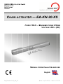
1
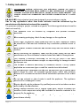
SIIMON RW WA-SYS STEME GMB M H MEDIENSTRA E ßE 8 94 4036 PASSA AU GERMANY E CHA AIN ACTU A UATO OR — EA A-KN N-20 0-XS S FOR RCE 150 0 N – MAXIMUM M STRO OKE 210 0 MM VOLTTAGE: 24V 2 ═ (D DC) MANUAL FOR INSTA ALLATIO ON AND USE E nglish BA A_EA-KN-20-XS_EN_10 Isssue: 1.0/112.2014 — Date: 5.2.2015 SIMON RWA-Sys stems pro oducts are e specially y manufacctured equiremen nts of in ssafe materials in compliance with the re legisllation in fo orce. When correctlyy mounted d, installed d and used in ac ccordance e with the present in nstructionss, our productss constitutte no dang ger to peo ple, anima als or prop perty. Produccts subjec ct to EU diirectives ccomply witth the esse ential requ uirements stipulated d by the la atter. markings m m mean that o our produc cts can be e sold and d installed throughou ut the Eu uropean Union U witho urther form mality. out any fu The mark on our produ ucts, packkaging and d user man nuals prrovided with the pro oduct, indicate “pressumed in conformity c y with direcctives” issu ued by the e EU. Sy ymbols used in n the man nual DAN NGER INFORM MATION This indication n draw the atten ntion abo out potential ers for safe fety and he ealth of pe eoples an nd animalss. dange This in nformation n give furtther sugge estions. ATTE ENTION This indication n draw the atten ntion abo out potential ers for the product itself. dange WAR RNING This indication n draw the atten ntion abo out potential ges to goo ods. damag onmental indicatio on draw the atte ention ab bout ENVIRON NMENTAL Enviro potenttial dange ers for the environm ment. INSTRUCTION Pa age 2 Isssue: 1.0/001.2015 — Date: 5.2.2015 Contents 1. Safety indications ................................................................................................ 4 2. Technical operating information .......................................................................... 6 3. Formulas and recommendations for installation ................................................ 7 3.1. Calculation of opening / closure force ....................................................... 7 3.2. Maximum opening based on sash height ................................................. 7 4. Technical data ..................................................................................................... 8 5. Construction and regulatory references .............................................................. 8 6. Id plate and marking data ................................................................................... 9 7. Electric power supply .......................................................................................... 9 7.1. Selecting the cross-section of the power supply cables ......................... 10 8. Electrical connection ......................................................................................... 10 9. Instructions for assembly .................................................................................. 11 9.1. Preparation for mounting the actuator .................................................... 11 9.2. Recessed mounting ................................................................................ 11 9.3. Surface mounting on top-hung windows opening outwards or bottom-hung windows .................................................................................. 12 10. Programming the actuator ................................................................................ 13 10.1. Opening stroke-end ................................................................................ 13 10.2. Closure stroke-end .................................................................................. 13 11. Checking for correct assembly .......................................................................... 14 12. Emergency manoeuvres, maintenance or cleaning .......................................... 14 13. Troubleshooting ................................................................................................ 14 14. Environmental protection .................................................................................. 15 15. Guarantee conditions and terms of delivery ..................................................... 15 16. Company addresses ......................................................................................... 16 BA_EA-KN-20-XS_EN_10 Page 3 1.. Safety y indicattions ATTENT TION BEF FORE INS TALLING THIS APP PLIANCE, ENSURE ALL SAF FETY INDICATIO ONS HAVE E BEEN RE EAD CARE EFULLY AND A UNDE RSTOOD IN ORDER R TO PREVENT CONTACT T WITH EL LECTRICIT TY, INJURY Y OR ANY OTHER IN NCIDENT. THE MANUAL SHOULD BE CONSE ERVED FO OR FURTHER CONSU ULTATION N AT A LA ATER DATE. EA A-KN-20-X XS chain actuators have bee en designe ed to move window ws or simila ar. Us se for an ny applic cations other o tha an those indicated d must b be autho orised by y the manufacturer after technical t review o of the ass sembly. To o guaranttee safetyy to people, anima als and go oods, the following g indicatio ons shoulld be ob bserved ccarefully. T The applliance must be iinstalled by comp petent an nd qualifiied techn nical p personnell. A After remo oving packaging, ch heck for any a damag ge on the appliance e. P Plastic ba ags, polys styrene, sm mall meta al parts su uch as na ails, staple es etc sho ould b be placed d out of th he reach o of children n as they constitute e a poten ntial source of rrisk. K Keep child dren, disa abled indivviduals an nd animals s away fro rom the wiindow and d its ccontrols. B Before co onnecting the applia ance, che eck that th he powerr supply has h the sa ame sspecificatiions as those indica ated on th he technic cal data lab bel on the e appliancce. T This macchine is destined d exclusive ely for the use fo or which it has been b d designed and the manufactu m urer accep pts no res sponsibility ty for dam mage incurrred b by improp per use. T The actua ator is de estined exxclusively for installlation ind doors. Forr any spe ecial a application n we reco ommend yyou consu ult the man nufacturerr beforeha and. T To ensure e efficient separatio on from th he grid, an n approve ed type of bipolar pu ulse sswitch sh hould be used. An n omnipollar genera al power switch with w minim mum d distance of o 3 mm between b co contacts sh hould be installed i u upstream of the con ntrol lline. D Do not usse solven nts or jetss of waterr to wash h the app pliance. The T applia ance sshould no ot be subm merged in water. R Repairs sh hould only y be perfo ormed by qualified personne p el at assisttance cen ntres a authorised d by the manufactu m urer. A Always re equest ex xclusive usse of orig ginal sparre parts. F Failure to o respect this ccondition could com mpromise safety an nd invalida ate the be enefits con ntained in n the w warranty for f the app pliance. IIn the eve ent of an ny problem ms or que eries, con nsult yourr agent or contact the m manufactu urer directtly. Pa age 4 Isssue: 1.0/001.2015 — Date: 5.2.2015 A ATTENTIION W With botto om hung windows injury cou uld be caused if th he window w accidentally ffalls. An appropriat a tely sized d flexible link l arm or o fall pre evention safety s sysstem d designed to resist a force eq qual to att least thrree times the total weight off the w window MUST M be in nstalled. C Check th hat the selected sstroke-end d allows the wind dow to open o with hout e encounterring any obstacles o w whatsoev ver. T The actu uator mus st be insstalled in n accorda ance with h the manufactur m rer’s iinstruction ns. Failure e to resp pect these e instructiions could ld compro omise saffety. P Power sup pply installlation mu ust comply y with any y regulatio ons in force. D Danger off crushing g or dragg ging. Durin ng function, when tthe actuattor closess the w window, a force of 230N is e exerted on n the bead d of the frrame, eno ough to crrush ffingers in the eventt of distracction. E Ensure th hat the stroke-en s d selectiion is les ss than one cen ntimetre from f m mechaniccal stop blocks, b str troke limitters or an ny physiccal obstac cles blockking o opening of o the sash h. IIn the eve ent of brea akage or m malfunctio on, switch the applia iance off at a the gen neral sswitch and d call for the t service es of a qu ualified tec chnician. BA A_EA-KN-20-XS_EN_10 Page 5 2. Technical operating information The chain actuator is used to open and close the window by means of a three-link steel chain. The movement is achieved with low-voltage (24V DC) electricity that powers a gear motor controlled by a functional electronic device. Window opening can be programmed, and the device allows excursion of the chain to strokes of 70, 125, 170 and 210 mm. For the return stroke, i.e., the closing of the window, the stroke-end is determined by an electronic process that automatically calculates the required power absorption to produce the movement of the window, and therefore no settings are required. The actuator can also be installed without the immediate availability of electricity for window movement; in this case the actuator will simply hold the window closed after assembly. The structure of the actuator is entirely metal, and it is also used for installation on heat and smoke exhaust systems as well as for room ventilation. The coupling between the actuator and support brackets fixed to the window frame is a quick-connect coupling that allows the actuator to rotate in order to adapt to the stroke of the chain, even on windows with reduced height. The brackets are fixed to the frame during actuator assembly with just two screws. Combined with the B-Lock product and perimeter fittings, it constitutes the security lock that keeps the window closed tight and guarantees a high thermal K. Page 6 Issue: 1.0/01.2015 — Date: 5.2.2015 3.. Formu ulas and d recom mmenda ations fo or installation 3.1. Calcula ation of opening g / closu ure force e Us sing the fformulas on this page, p app proximate e calculattions can be made e for the force f re equired to o open orr close th he window w consid dering all the facto ors that determine d e the ca alculation n. Symbols S u used for th he calculattion F (kg) = Fo orce for op pening or closing C (cm) = O Opening stroke (actuator stro oke) For ho orizontal light dom mes or skyliights P (kg) ( = Weeight of the w window (mobile sash onnly) H (cm) ( = He eight of the e mobile sash s For verticall windows s TOP T HUNG WINDOWS W , OUUTWARD OPENING (A) BOTTOM B HUNG WIND DOWS (B) F = 0,54 x P F = 0,54 x P x C : H (Eventual ( weight of snow or wind w on the e cupola c sho ould be callculated se eparately). (Even ntual load of o favourabble or unfavourable wind w on the e sash shou uld be calcuulated sepa arately.) 3.2. Maximu um open ning bas sed on sash s height Th he selection of the e actuator stroke sshould be e made based b on the heigh ht of the sash an nd its app plication. As a gen neral rule, never select a sttroke gre eater than n the heig ght of the window w frame; select s the e stroke d directly below it. WARNING. The actuator is d designed d to be re ecess mo ounted on n the window fr frame. C Check tha at during g the stro oke the chain c doe es not tou uch the profile p off the ssash, therre are no o obstaclles to opening the e window w and the e chain does d n not push against a th he windo w frame. BA A_EA-KN-20-XS_EN_10 Page 7 4. Technical data Model Force exerted by thrust and traction Strokes (can be selected at any time) Power supply voltage Rated absorbed current Power absorbed at nominal load No load speed Duration of no load stroke (210 mm) Type of service Operating temperature Protection index for electrical devices Adjustment of connection to window frame Parallel powering of two or more motors Operation with B-LOCK electromechanical lock Synchronised function Static hold force Stroke-end at opening Stroke-end at closing Chain exit Length of power cable Dimensions Weight EA-KN-20-XS – 24V 150N 70, 125, 170, 210 mm 24 V DC ═ 0,32 A 7,5 W 8 mm/s 27 s S2 of 3 min - 5 + 65 ºC IP32 Automatic definition of position YES (max 20 actuators) Yes Not foreseen 1.000 N Electronic by dip-switch At absorption of power Central 2m 28x28x310 mm 0.720 kg The data indicated in these figures is not binding and is subject to variation without notification. 5. Construction and regulatory references The EA-KN-20-XS chain actuator is designed and built to open and close top-hung windows opening outwards, bottom-hung windows or up-and-over roof windows. Its use is specifically intended for ventilation, air conditioning of rooms, smoke and heat exhaust systems and, if used in combination with the B-Lock window lock, also as a building security system; it is highly recommended that the actuator not be used for any other purpose unless approved by the manufacturer beforehand. Electrical connections must comply with standards in force on the design and production of electrical appliances. The actuator has been manufactured according to European Union directives and conforms to marking and following EMC rules for interference. Any eventual service or control device for the actuator must be produced according to standards in force and must comply with the standards issued by the European Community. Page 8 Issue: 1.0/01.2015 — Date: 5.2.2015 Th he actua ator is in ndividually y packag ged in a cardboa ard conta ainer and d each pack co ontains: 2 24V═ elecctrical ac ctuator co omplete of o connector for ffeeding cable c w wiring. 2 support brackets s 2 half-bra ackets fo or attach h to the frame, ccomplete with pin In nstruction n manual 6.. Id plate and marking m data All actuatorrs have markin ng and arre destine ed for use e in the E European Union without further requ uirements. he ma arking on n the prod duct, pacckaging and indica ations for use prov vided with h the Th prroduct ind dicate ‘p presumed conform mity to th he directives’ issu ued by the t European Co ommunityy. 7.. Electriic powe er supplly Th he EA-KN N-20-XS actuator a is s powere ed with a voltage of o 24V (D DC). The power su upply ca able has three con nductors:: the first conducto or BLACK K “1” thatt should be b conne ected to o the + (p positive) CLOSES th he windo ow; the se econd co onductor B Black “2 2” that sh hould be e conneccted to the e + (posittive) OPEENS the window; w th he third cconductorr Black “3” “ is th he conducctor used d for the B-Lock B co ontrol com mmunicattion signa al. Th he 24V llow-voltag ge actua ators can n be pow wered using a sta ation with emergency ba atteries or an approved cla ass II pow wer supplly unit (do ouble saffety insullation) witth an ou utput volta age of 24 4V (-15% % ÷ +15% %, in otherr words min. m 20.4V V, max. 27.6V), 2 th hat is to say, size ed based d on the number n o of actuato ors conne ected. Th he EA-KN-20-XS po ower su upply musst be suita ably prote ected by fuses. BA A_EA-KN-20-XS_EN_10 Page 9 7.1. Selecting the cross-section of the power supply cables With the 24V (DC) power supply, it is necessary to check the cross-section of the cable, which should be calculated based on the length of the cable itself. The table below specifies the maximum length of the cables for connection of a motor. Cable section Max cable length 4,00 mm² 2,50 mm² 1,50 mm² 0,75 mm² 0,50 mm² ~ 270 m ~ 170 m ~ 100 m ~ 50 m ~ 35 m 8. Electrical connection The machines are equipped with a power supply cable constructed in compliance with safety standards and restrictions on radio-frequency interference. The power supply cable - with conductors having a cross-section of 0.5 mm² - must be wired to a special connector as shown in the diagram below, in the following sequence: 1 – BLACK-coloured conductor, marked “1”; 2 – BLACK-coloured conductor, marked “2”; 3 – BLACK-coloured conductor, marked “3”: For harness, please follow this diagram: Note: the first conductor BLACK “1” that should be connected to the + (positive) CLOSES the window; the second conductor Black “2” that should be connected to the + (positive) OPENS the window; the third conductor Black “3” is the conductor used for the B-Lock control communication signal. Page 10 Issue: 1.0/01.2015 — Date: 5.2.2015 9.. Instruc ctions for f asse embly These T ind dications s are for specialis ised tech hnical pe ersonnel and bas sic work and safety techniiques are re not ind dicated. All prepara atory, asssembly an nd electriccal conne ection operations must be performe ed by sp pecialised d technical person nnel to g guarantee e optima al functio n and service off the ac ctuator. C Check tha at the follo owing fun ndamenta al conditio ons have been me et: Acctuator sp pecification ns must b be sufficie ent for movement m of the window w without in the tecchnical da encountering any ob bstacle. Th he limits indicated i ata table must no ot be supe erseded (p page 7) and the mo ost appropriate stro oke shoulld be sele ected. Ca alculationss should be b checke ed using th he formula a indicate ed on page e 6. al powerr supply corresp ponds to that Attention. Check that the electrica ind dicated on the TEC CHNICAL DA ATA labell on the machine. m nsure tha at the ac ctuator h has not been da amaged during trransport, first En vissually and d then by y powering in both direction ns. Ch heck that the width h of the in nside of the t windo ow (wherre the acttuator is to t be assembled) is over 360 3 mm, otherwis se the acttuator sho ould not be installed. Ch heck thatt once th he actuattor has been b insttalled, ch hain com mpletely in n, the win ndow is perfectly p closed. Iff this is not n the ca ase the acctuator will w not fun nction correctly ass the wind dow will n not close correctly y. 9.1. Preparation for mountting the actuato or Be efore beg ginning to o mount the actu uator, dep pending on o the tyype of ap pplication, the wiindow fra ame mustt be prepared by ccarrying out o the following o operations s: 9.2. Recess sed mou unting For reccessed mounting m , the win ndow frame must be pre epared by y milling and making g two holes as indicated i n the dia agram be elow. The e depth of the milling m must be e at leastt 30 mm. BA A_EA-KN-20-XS_EN_10 Page 11 Then m make tw wo Ø4.5 holes o n the sa ash for the attacchment bracket. The measurrements are a specified in th he diagram m below. 9.3. Surface e mounting on top-hun ng wind dows op pening outward o s or bottom m-hung windows w s The acctuator can c also be surfface mounted on n top-hu ng windows ope ening outward ds or dorrmer windows an nd on botttom-hung g window ws, howe ever for th hese specificc applicattions spe ecial supp port brack kets are required for the actuator which w must be e supplie ed separa ately. The two o half-bra ackets atttaching tthe actua ator to the e sash, h owever, are the same s standarrd bracke ets supplied with th he actuattor and in ncluded in n the pac ckage. To prep pare the holes on n the win ndow fram me and sash, s use e the drilling template include ed in the package of the sp pecial brackets; this templlate also specifiess the diamete er of the e holes and a their position in refere ence to tthe innerr edge off the window w frame. Wa Warning. In I order to preve ent unple easant mishaps m w with the machine and po ossible sa afety haza ards, carrefully cho oose the length o of the clam mping sccrews in order to avoid damaging d g the pow wer supply cabless during the mou unting pro ocedure. In order to carry out a cost-e effective a and prec cise up-to-standard d work, itt is best iff you prrepare the e followin ng comple ementaryy material: small parts, p equ uipment and a tools.. Fasten ning on metal m window fram mes: M4 threaded t inserts ((2 pieces s for recessed mountting and 4 pieces for surface moun nting), M4 4x12 flat h head metric screw ws (2 piecess (4 piece es for surrface mou unting)). Fasten ning on wooden w window w frrames: Ø4 4 self-thrreading w wood scre ews (2 piieces for reccessed mounting m and 4 pie eces for surface mounting m g), with an approp priate me. length for the tyype of window fram Pa age 12 Isssue: 1.0/001.2015 — Date: 5.2.2015 Fastening on PVC window frames: Ø3.9x13 self-threading metal screws (2 pieces for recessed mounting and 4 pieces for surface mounting), with an appropriate length for the type of window frame. Equipment and tools: tape-measure, pencil, drill/electric screwdriver, set of drill bits for metal, insert for screwing in, electrician's scissors, screwdrivers. 10. Programming the actuator 10.1. Opening stroke-end The opening stroke-end of the actuator can be adjusted by selecting the dipswitches located inside the actuator underneath the black rubber plug (T) (see fig. below), near the label that indicates the state of the dip-switches. The setting can be made very easily by selecting the dip-switches as specified in the table below. STROKE (mm) 70 125 170 210 DIP-SWITCH 1 2 ON OFF OFF ON OFF OFF OFF OFF 3 OFF OFF ON OFF 4 OFF The actuator is factory-set with the longest stroke (210 mm). 10.2. Closure stroke-end The stroke-end at closure is automatic and cannot be programmed. The actuator stops when the charge is absorbed when the window is completely closed and the weather stripping is completely depressed, or when the charge absorbed is more than 15% of the nominal charge. After each closure or intervention of electronic protection devices, the chain will move about 1 mm in the opposite direction to give correct compression to the seals and release the mechanical parts. BA_EA-KN-20-XS_EN_10 Page 13 11 1. Che ecking fo or corre ect asse embly Ch heck thatt the wind dow is p erfectly closed c att corners and that there are a no ob bstacles caused c by y incorrecct positioning during assem mbly. Ch heck that when the window w frame is i closed the chaiin terminal is at le east a few w millime etres awa ay from th he actuattor body. This wil l ensure the wind dow is pro operly clo osed and d seals a are corre ectly compressed.. In the event e tha at this should not be the case the ere is no o guarantee that the wind dow is closed c correctly. Ch heck that hinges and a supp ort brack kets are aligned a to o each other and tightly t fixe ed againsst the win ndow fram me with screws s fix xed corre ectly into position. p Ch heck that the wind dow reac hes the desired d position p a according to the sttrokeen nd selecte ed. 12 2. Eme ergency y manoe euvres, mainte enance or o clean ning In the eve ent that th he windo ow frame e should require manual m o opening due d to po ower failure or problem with w the mechanism m m or for normal n ma aintenancce or exte ernal clea aning off the wind dow frame e, in built--in actuattors it’s necessary y to perforrm these operation ns: 1. Unsccrew the two t screw ws that fixx the sas sh to the attachme a ent bracke et. 2. Take e care during this operation n since th he bracke et, which h is in two o pieces after remo oving the screws, may fall a as it is no o longer secured. s 3. Manu ually ope en the win ndow fram me. ATTEN NTION: DA ANGER – the wind dow could d fall as tthe sash h is no lo onger held in i position n by the cchain. 4. Afterr maintenance and d/or clean ning repe eat points 1 and 2 in revers se order. 13 3. Trou ublesho ooting Po ossible ca auses of malfuncttion durin ng installa ation or us se. Prroblem Po ossible ca ause No ele ectricity att feeder Ac ctuator do oes not work w Pa age 14 Cable not connected or wire diisconnectted. Solu ution Ch heck status of circuit bre eaker or safety s swittch Ch heck electtrical co nnections s at reducction otor mo Isssue: 1.0/001.2015 — Date: 5.2.2015 14 4. Environmental pro otection n A All materials used in the ma anufacture e of this appliance a are recyc clable. W We recom mmend that the devvice itselff, and any y accesso ories, pac ckaging, etc. e b be sent to t a centre for eccological recycling as estab blished frrom laws in fforce on recycling. r T The devicce is mainly made e from the e followin ng materia als: alum minium, zin nc, iron, plasttic of various type e, cuprum m. Dispose e materia als in conformity with w local regu ulations ab bout remo oval. 15 5. Gua arantee conditio ons and d terms s of deliv very T The man nufacturerr will gua arantee good g function of the appliance. The T m manufactu urer shalll undertakke to replace defec ctive partts due to poor quality h article 1490 of the m materials or manufacturing defects in accord dance with t C Civil Code e. T The guara antee cov vers prod ducts and d individual parts ffor 2 yea ars from the t d date of purchase. The latte er is valid d as long as the p purchaserr possessses p proof of purchase and a comp pletion of all agreed d conditio ons of pay yment. T The produ uct must be used as norma ally intend ded. The product is subjectt to n natural wear w and tear. In ccase of material m defect d cla aims, the ese shall be a asserted in writing,, stating tthe source e of supply of the d device. The followiing a applies with respec ct to the g guarantee e: “Generral conditiions for th he supplyy of p products and serv vices of tthe electrrical and electron ics indus stry (“Gre een d delivery te erms” – GL)”. G Thesse can be e found att our hom mepage www.simo w onrrwa.com.. We would be plea ased to se end you a copy up pon reque est. T The curre ently valid d conditio ons for products p and a serviices of th he electriccal a and electtronics in ndustry (g green dellivery terms) applly for delliveries and a sservices, including g the supp plementary clause e “Extend ed retenttion of titlle”. T These are e published by ZV VEI Frank kfurt. If yo ou are no ot familiar with thesse, w we would d be hap ppy to se end them m to you u. The ag greementts are also a available for downlload at ww ww.simo on-rwa.co om. P Passau iss the established le egal venue. BA A_EA-KN-20-XS_EN_10 Page 15 16. Company addresses Germany Simon RWA® Systeme GmbH Medienstraße 8 D – 94036 Passau Tel.: +49 (0)851 98870 - 0 Fax: +49 (0)851 98870-70 E-Mail: [email protected] Web: www.simon-rwa.de Switzerland Simon RWA® Systeme AG Allmendstrasse 8 CH – 8320 Fehraltorf Tel.: +41 (0)44 956 50 30 Fax: +41 (0)44 956 50 40 E-Mail: [email protected] Web: www.simon-rwa.ch Hungary Simon RWA® Rendszer Kft. Sodras utca 1. fszt. 1 H – 1026 Budapest Tel.: +36 (0)30 552 0424 E-Mail: [email protected] Page 16 Issue: 1.0/01.2015 — Date: 5.2.2015