1
PSK-1: Analog Systems of 1. and 2. Order
M. Schubert
2.2 Using Reference CH1 for Accurate Measurements
Right-click in the diagram to open the
shortcut menu. Use the shortcut menu
to optimize the diagram, select the
grid and zoom in the diagram. After
having zoomed in, click Optimize to
get back to an optimized diagram.
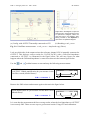
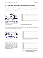
(a) Config. with OUTPUT not internally connected to CH1 (b) Vector=V(CH2)/V(CH1)
Fig. 2.2: Gain/Phase measurement: Vector=V(CH2)/V(CH1) = Amplitude⋅exp(j⋅Phase).
Images taken from Bode 100 User Manual [2].
Click the Device Configuration
toolbar button or select Configuration → Device
Configuration… from the Bode Analyzer Suite’s menu bar or to get into the configuration
menu. Click on the switch circled red in Fig. 2.2 to get the illustrated setting of the switch.
The connection between OUTPUT and reference input CH1 has now to be made externally.
Note to which side of the output resistor the reference channel CH1 is connected now. The
measurement will always be correct independently of the load resistor. Use the setup of Fig.
2.2 with a source frequency 1KHz to try the two situations below:
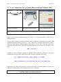
Which amplification do you measure for this short circuit
(dB and factor)?
OUTPUT
CH1 CH2
OUTPUT
CH1
0dB = Factor 1
Which amplification do you measure now (dB and
factor)?
CH2
0dB = Factor 1
50Ω
This kind of measurement is always correct but a more uncomfortable due to the required
additional cable connected to the reference channel CH1.
-4-