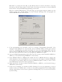
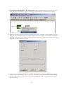
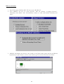
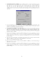
1
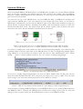
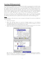
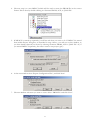
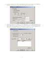
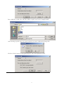
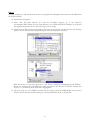
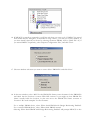
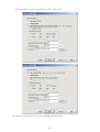
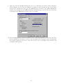
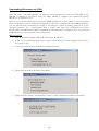
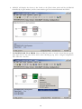
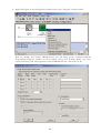
HUNT ENGINEERING
Chestnut Court, Burton Row,
Brent Knoll, Somerset, TA9 4BP, UK
Tel: (+44) (0)1278 760188,
Fax: (+44) (0)1278 760199,
Email: [email protected]
www.hunteng.co.uk
www.hunt-dsp.com
Using iMPACT with FPGA Modules
v 1.2 J.Thie 19-12-05
The HERON-FPGA and HERON-IO families are ranges of HERON modules with FPGAs, often
combined with some interface capability. Many of the HERON-FPGA and HERON-IO modules provide
a connection for the Xilinx download tool, iMPACT along with a FLASH PROM that can be
programmed with a bit-stream.
For HERON-FPGA and HERON-IO modules that provide a JTAG connector and a PROM, by using
iMPACT it is possible to directly configure the FPGA on the module, or download a bit-stream to the
PROM. When the PROM has been written with a bit-stream this enables the FPGA module to
automatically configure the FPGA from the PROM as soon as power is applied to the module, allowing
the module to perform as part of an embedded system.
The application FPGA and FLASH PROMs can be programmed and reprogrammed via the JTAG chain
using Xilinx cables such as the Parallel 3 or Parallel 4 cables. The application FPGA (if connected on your
module) can be programmed directly from the design bit-stream file (.bit file), while the PROMs must be
programmed with the contents of a ‘MCS’ file, generated in your design tools from the previously created
bit-stream.
This document discusses the steps involved in configuring an application FPGA and in generating the
correct MCS file and loading the contents of that file into the Flash PROM on the module you are using.
History
Rev 1.0
First written
Rev 1.1
Updated for ISE 6.x and new ‘xcf08p’ PROM part
Rev 1.2
Updated for ISE 7.x
HUNT ENGINEERING is a trading style of HUNT ENGINEERING (U.K.) Ltd, Co Reg No 3333633
Directors P.Warnes & N.J.Warnes. Reg’d office 34 & 38 North St, Bridgwater, Somerset TA6 3YD. VAT Reg’d No GB 515 8449 31
Determine PROM part
HUNT ENGINEERING HERON-FPGA and HERON-IO modules use several different PROM
parts. At the time of writing, two different parts are used: ‘xc18v04’ and ‘xcf08p’. The programming
sequence is slightly different between these. Therefore, as a first step, we must determine what PROM
part is used on your module.
You can look on top of the PROM device on your HERON-FPGA or HERON-IO modules and
verify what the PROM part is (the user manual for your module will show where you can find its
PROM part). Alternatively, you can start up ‘iMPACT’ (part of the Xilinx tools installation). Select the
default choices ‘Configure Devices’, ‘Boundary-Scan Mode’, and ‘Automatically connect to cable and
identify Boundary-Scan chain’. The JTAG chain will be shown together with all devices that were
detected on the chain. The part numbers are written below the devices.
Picture 1. On the left side you can see a ‘xcf08p’ PROM part detected (example FPGA9 module).
On the right hand side you can see a ‘xc18v04’ PROM part detected (example FPGA3 module).
If you have a ‘xcf08p’ part, verify whether you have an ES (Engineering Sample). If you find that ‘ES’
is printed under or after the part name on the PROM device you have an Engineering Sample. When
using ‘iMPACT’, in the bottom text window scroll up until you find ‘Manufacturer’s ID = Xilinx
xcf08p …’, there’s a version number listed here. If it’s ‘0’, you have an Engineering Sample.
Picture 2. An Engineering Sample (ES) ‘xcf08p’ PROM part
If you have a ‘xcf08p’ Engineering Sample, you must use Xilinx Parallel Cable IV (ES parts will not
work with Xilinx Parallel Cable III). Also, verify that your cable is set to run at 5 Mhz. You can verify
these settings at the status line towards the bottom of the ‘iMPACT’ window.
Picture 3. ‘iMPACT’ has detected a Xilinx Parallel IV cable running at 5 Mhz, using parallel port 1.
At the moment of writing, HERON-FPGA1 to 6 and HERON-IO1 to 4 use ‘xc18v04’ PROM devices,
and HERON-FPGA7 onwards and HERON-IO5 onwards used ‘xcf08p’ devices. But this may well
change in future so please make sure what PROM part is used on your HERON module.
2
Generating a PROM programming file
The Flash Proms on HERON-FPGA and HERON-IO modules are programmed via the JTAG chain,
using a Xilinx Parallel Cable (version III or IV -- but if you have an ES ‘xcf08p’ part, you can only use
IV). As part of your Xilinx tools there will be a utility called ‘iMPACT’ that is used to program a device.
The ‘iMPACT’ utility uses MCS files (extension ‘.mcs’) and in some case CFI files (extension ‘.cfi’).
Xilinx tools before 6.0 will only create MCS files, Xilinx tools version 6.0 and later can optionally also
create CFI files. HERON modules with a ‘xc18v04’ PROM part only use a MCS file, HERON
modules with a ‘xcf08p’ PROM part also need a CFI file, to have the PROM device programmed.
These files are generated by the Xilinx ‘PROM File Formatter’ after the *.rbt file has been generated.
The sequence to generate the files is slightly different between ISE 6.x, ISE 5.x, ISE 4.2 and ISE 4.1.
The following sections discuss how to generate the necessary files for each of the ISE design tools.
ISE 7.x
For this example, we will assume that we want to program the Example1' bit-stream into the PROM of
the FPGA module.
1. Start Project Navigator.
2. Select ‘File Æ Open Project’. To load the Example1 project, go to the directory
dir\example1\ISE (where dir is the local directory you copied the FPGA examples to) and open
the appropriate project file for the board type you are using.
3. Check that ‘CCLK’ has been selected for the start-up clock (this can be found in the ‘Startup
options’ tab of the Generate Programming File Process Properties window).
With this done, you can then generate a *.rbt file by “Generate Programming File Æ Run”.
When you generate the *.rbt bitstream, make sure that in the ‘Sources in Project’ window the
‘top-rtl (..\..\Common\TOP.vhd)’ line is highlighted.
3
4. The next step is to start iMPACT which will be used to create the PROM file in the correct
format. This is done by double-clicking on ‘Generate PROM, ACE, or JTAG File’.
5. If iMPACT is started up separately, it will first ask what you want to do. If iMPACT is started
from within Project Navigator, as described in step 4 above, you will not see this window, as
you have already selected you choice by selecting ‘Generate PROM, ACE or JTAG File’. So, if
you started iMPACT separately, first select ‘create a new project (.ipf)’:
6. At the next window select ‘Prepare Configuration Files’, and click ‘Next’.
7. The next window asks want you want to create. Select ‘PROM file’ and click ‘Next’.
4
8. In the next window, select ‘MCS’ for the PROM file format, enter the name for the PROM file
and check that the location is correct. We used ‘example1’ for the file name.
9. In the next window, for a ‘xcf08p’ or ‘xcf16p’ PROM device, select ‘Enable Revisioning’, and
add the PROM device on your module (e.g. ‘xcf16p’ for an IO5 module). Selecting ‘Enable
Revisioning’ will prompt iMPACT to also generate a CFI file. For a ‘xc18v04’ PROM device,
select ‘Auto Select PROM’ instead. After you made your choice, click ‘Next’.
5
10. Click ‘Next’ again in the following window.
11. In the Add Device File window click on the ‘Add File’ button, and select the ‘top.bit’ bit-stream
that will have been generated last time you ran the bit-stream generation process. When this
process has run and you are asked if you would like to add another bit-stream, select ‘No’. Next
click on the ‘Finish’ button, and the MCS files will be created. Additional CFI files will be
created if you selected the ‘Enable Revisioning’ option earlier on.
6
Press ‘Add File’ to add a file. The file to add is ‘top.bit’ in d:\io5v1\example1\ISE.
After selecting ‘top.bit’, click ‘No’ when asked if you want to add another design file:
Click the ‘Finish’ button to start generating the ‘mcs’ (and optional ‘cfi’ file).
7
ISE 6.x
For this example, we will assume that we want to program the Example1' bit-stream into the PROM of
the FPGA module.
12. Start Project Navigator.
13. Select ‘File Æ Open Project’. To load the Example1 project, go to the directory
dir\example1\ISE (where dir is the local directory you copied the FPGA examples to) and open
the appropriate project file for the board type you are using.
14. Check that ‘CCLK’ has been selected for the start-up clock (this can be found in the ‘Startup
options’ tab of the Generate Programming File Process Properties window).
With this done, you can then generate a *.rbt file by “Generate Programming File Æ Run”.
When you generate the *.rbt bitstream, make sure that in the ‘Sources in Project’ window the
‘top-rtl (..\..\Common\TOP.vhd)’ line is highlighted.
15. The next step is to start iMPACT which will be used to create the PROM file in the correct
format. This is done by double-clicking on ‘Generate PROM, ACE, or JTAG File’.
8
16. If iMPACT is started up separately, it will first ask what you want to do. If iMPACT is started
from within Project Navigator, as described in step 4 above, you will not see this window, as
you have already selected you choice by selecting ‘Generate PROM, ACE or JTAG File’. So, if
you started iMPACT separately, select ‘Prepare Configuration Files’, and click ‘Next’.
17. The next window asks want you want to create. Select ‘PROM file’ and click ‘Next’.
18. In the next window, select ‘MCS’ for the PROM file format, enter the name for the PROM file
and check that the location is correct. With ISE version 6.1 you might see that ‘PROM File
Name’ actually holds the location, in that case move the ‘PROM File Name’ contents to
‘Location’. We used ‘example1’ for the file name.
For a ‘xcf08p’ PROM device, select ‘Xilinx Serial PROM with Design Revisioning Enabled’.
For a ‘xc18v04’ PROM device, select ‘Xilinx Serial PROM’ instead.
Selecting ‘Xilinx Serial PROM with Design Revisioning Enabled’ will prompt iMPACT to also
9
generate a CFI file. After you made your choice, click ‘Next’.
19. In the next window tick ‘Auto Select PROM’ and click ‘Next’.
10
20. Click ‘Next’ again in the following window.
21. In the Add Device File window click on the ‘Add File’ button, and select the ‘top.bit’ bit-stream
that will have been generated last time you ran the bit-stream generation process. When this
process has run and you are asked if you would like to add another bit-stream, select ‘No’. Next
click on the ‘Finish’ button, and the MCS files will be created. Additional CFI files will be
created if you selected ‘Xilinx Serial PROM with Design Revisioning Enabled’ earlier on.
11
ISE 5.x
For this example, we will assume that we want to program the Example1 bit-stream into the PROM of
the FPGA module.
1. Start the Project Navigator.
2. Select ‘File Æ Open Project’. To load the Example1 project, go to the directory
dir\example1\ISE (where dir is the local directory you copied the FPGA examples to) and open
the appropriate project file for the board type you are using.
3. Check that ‘CCLK’ has been selected for the start-up clock (this can be found in the ‘Startup
options’ tab of the Generate Programming File Process Properties window). With this done,
you can then generate a *.rbt file by “Generate Programming File Æ Run”.
4. The next step is to start iMPACT which will be used to create the PROM file in the correct
format. This is done by double-clicking on ‘Generate PROM, ACE, or JTAG File’.
5. When iMPACT first starts it will ask what you want to do. Select ‘Prepare Configuration Files’,
and click ‘Next’.
6. The next window asks want you want to create. Select ‘PROM file’ and click ‘Next’.
12
7. In the next window select ‘Xilinx Serial PROM’, ‘MCS’ for the file format, enter the name for
the PROM file and check that the location is correct. Then click ‘Next’.
8. In the next window tick ‘Auto select PROM’ and click ‘Next’.
9. Click ‘Next’ again in the following window, ‘File Generation Summary’.
10. In the Add Device File window click on the ‘Add File’ button, and select the ‘top.bit’ bit-stream
that will have been generated last time you ran the bit-stream generation process. When this
process has run and you are asked if you would like to add another bit-stream, select ‘No’. Next
click on the ‘Finish’ button, and the MCS file will be created.
13
ISE 4.2
For this example, we will assume that we want to program the Example1 bit-stream into the PROM of
the FPGA module.
1. Start the Project Navigator.
2. Select ‘File Æ Open Project’. To load the Example1 project, go to the directory
dir\example1\ISE (where dir is the local directory you copied the FPGA examples to) and open
the appropriate project file for the board type you are using.
3. Check that ‘CCLK’ has been selected for the ‘Start-Up Clock’ (this can be found in the ‘Startup
options’ tab of the Generate Programming File Process Properties window). With this done,
you can then generate a *.rbt file by “Generate Programming File Æ Run”.
4. The next thing is to start the PROM file formatter. In ISE 4.2, the PROM file formatter starts
correctly, it creates a new *.pdr file for you (if none was present yet). New *.pdr files still need
to be saved, thus answer ‘yes’ if asked if you want to save the file. Save into the default offered
by ISE, which should be your project directory.
5. Double click on “Generate PROM File”. The PROM file formatter should start, with a proper
filename under “Data Stream #1”. Make sure that the file selected is the proper file. For
example1, this is dir \example1\ISE\top.bit.
6. Make sure that File Æ PROM Properties are set to ‘MCS-86’ and ‘Serial’, ‘Serial’ should be
selected despite the fact that the hardware is parallel to work around the bug in the Xilinx
software, the software also then gives the PROM device in terms of the Xilinx PROM part
number. For example, for the HERON-FPGA3 the PROM type is an XC18V04 so ensure this
is selected for the PROM Device. Select “OK” to continue.
14
7. Use File Æ Create PROM to create a .mcs file. If the tools asks you to save the *.pdr file, do so.
Quit the PROM File Formatter. You can verify the PROM File Formatter step by checking that
your project directory now has a *.mcs file. In the case of example1, this would be dir
\example1\ISE\top.mcs.
15
ISE 4.1
For this example, we will assume that we want to program the Example1 bit-stream into the PROM of
the FPGA module.
1. Start Project Navigator
2. Select ‘File Æ Open Project’. To load the Example1 project, go to the directory
dir\example1\ISE (where dir is the local directory you copied the FPGA examples to) and open
the appropriate project file for the board type you are using.
3. Check that “CCLK” has been selected for the “Start-Up Clock”, then generate a *.rbt file by
“Generate Programming File” Æ Run.
4.
The next thing would be to run the PROM file formatter. However, if there’s no ‘pdr’ file in
your project yet, you cannot start the PROM file formatter from within ISE 4.x. What you can
do is create an empty ‘pdr’ file, save it, then go back to ISE4.x:
5. Start Æ Programs Æ Xilinx ISE 4.x Æ Accessories Æ PROM File Formatter
6. Immediately do a File Æ Save Description. Save the ‘pdr’ file in your project directory. For
example1, that would be dir \example1\ISE, use as name ‘top.pdr’.
7. Exit the PROM file formatter.
8. Now you will be able to start the PROM file formatter from within ISE 4.x. Double click on
“Generate PROM File”. The PROM file formatter should start, but now with a proper filename
under “Data Stream #1”. Make sure that the file selected is the proper file. For example1, this is
dir \example1\ISE\top.bit.
16
9. Make sure that File Æ PROM Properties are set to ‘MCS-86’ and ‘Serial’. ‘Serial’ should be
selected despite the fact that the hardware is parallel to work around the bug in the Xilinx
software, the software also then gives the PROM device in terms of the Xilinx PROM part
number. For example, for the HERON-FPGA3, the PROM type is an XC18V04 so ensure this
is selected for the PROM device. Select “OK” to continue.
10. From the PROM File Formatter window use File Æ Create PROM to create the .mcs files.
Quit the PROM File Formatter. You can verify the PROM File Formatter step by checking that
your project directory now has a *.mcs file. In the case of example1, this would be dir
\example1\ISE\top.mcs.
17
Downloading Bit-streams via JTAG
Once the *.mcs, *.bit, and optional *.cfi files have been generated they can be downloaded to the
PROMs or directly to the FPGA using the Xilinx ‘iMPACT’ software. We recommend starting
iMPACT as a stand-alone tool.
Please note, for some module types such as the HERON-FPGA3, the user FPGA is not in the JTAG
chain and therefore cannot be directly configured. In the case of modules like the HERON-FPGA3,
you can still effectively download your design to the FPGA via JTAG for debug purposes. If on the
“Program Options” the “Load FPGA” box is ticked, then when the configuration has been
downloaded to the PROM the FPGA is automatically and immediately configured. Also note, with the
HERON-FPGA3 it is not possible to use Chip-scope.
ISE 6.x and 7.x
1. Start Æ Programs Æ Xilinx ISE 6 Æ Accessories Æ iMPACT.
2. In ISE 7.x you will be asked whether to open a recent project. For this example, select ‘create a
new project (.ipf)’.
3. At the next window select the default ‘Configure Devices’
4. Then select the default ‘Boundary Scan Mode’
5. Again select the default “Automatically connect to cable and identify boundary-scan chain”.
18
6. iMPACT will display the devices it has found on the JTAG chain, which will be the PROM
identified by its part number, and for some module types the chain will include the FPGA.
7. TO DOWNLOAD TO A PROM: Select the PROM (click on it and it should become green)
then right click on the same device and a menu should pop up, select “Assign Configuration
File” select the *.mcs file.
19
8. Right Click again on the selected device and this time select “Program” from the menu.
With the ‘xcf08p’ and ‘xcf16p’ PROM devices, this will bring up the “Advanced PROM
Programming Options” window. In this window, ensure that “Parallel Mode” has been
selected. Selecting ‘OK’ will program the selected PROM with the *.mcs and *.cfi file.
20
With ISE 7.x you must also tick ‘Rev 0’, with ISE 6.x there’s no need to tick ‘Rev 0’. You may
also want to tick the ‘Erase’ and/or ‘Verify’ boxes. Note that you may have to erase the PROM
device before a successful PROM programming is successful.
With the ‘xc18v04’ PROM device, this will bring up the Program Options window. In this
window, ensure that “Parallel Mode” has been selected. Selecting ‘OK’ will program the
selected PROM with the *.mcs*.cfi) file.
9. If the programming was successful, you’ll see a message “Programming Succeeded”. This
message is only displayed for a few seconds. In the command window as well, upon success
you’ll see “Programming succeeded successfully”. In case the programming failed, often the
reason is that the PROM hasn’t been erased. Right click again on the PROM device and this
time select Erase. When that is done, try to program the PROM device again.
10. To test the PROM programming, power down the PC (if using a carrier board like HEPC8 or
HEPC9), or the board (if using a HEBASE1 or later board).
11. Every HERON-FPGA or HERON-IO module that has a PROM fitted has a jumper that
selects whether to boot from PROM or not. In most cases this jumper is labelled ‘BFPROM’
on the PCB of the module. Make sure that the BFPROM jumper is fitted, to select to boot
from PROM when the board or PC is powered on.
12. Power up the PC (if using a carrier board like HEPC8 or HEPC9), or the board (if using a
HEBASE1 or later board).
13. In the case of example1, you should see LED 4 flashing. For your own application, it may be
useful to write to an LED as well – so that you can verify your application was loaded properly
and has started. Better, use the clock to generate a flashing LED, so you can be sure the clock is
up and working.
21
14. TO DOWNLOAD DIRECT TO THE FPGA: Select the FPGA device on the JTAG chain
then right click on the device, click on “Assign Configuration File”, then select the *.bit file.
15. Right Click again on the selected device and this time select “Program” from the menu, this will
bring up the “Program Options” window. Make sure that ‘Verify’ is not ticked (otherwise
iMPACT will look for an *.msk file, and we haven’t created one). Then select OK and this will
program the FPGA with the *.bit file.
16. In the case of example1, you should see LED 4 flashing. For your own application, it may be
useful to write to an LED as well – so that you can verify your application was loaded properly
and has started. Better, use the clock to generate a flashing LED, so you can be sure the clock is
up and working.
22
ISE 5.x and earlier
1. Start Æ Programs Æ Xilinx ISE 5 Æ Accessories Æ iMPACT.
2. Next, iMPACT will ask you some questions. Take the defaults: “Configure Devices”,
“Boundary Scan Mode” and “Automatically connect to cable and identify boundary-scan
chain”.
3. iMPACT will display the devices it has found on the JTAG chain, which will be the PROM
identified by its part number, and for some module types the chain will include the FPGA.
23
4. TO DOWNLOAD TO A PROM: Select the PROM (click on it and it should become green)
then right click on the same device and a menu should pop up, select “Assign Configuration
File” select the *.mcs file. Right Click again on the selected device and this time select
“Program” from the menu, this will bring up the Program Options window, ensure that
“Parallel Mode” has been selected. Selecting OK will program the selected PROM with the
*.mcs file.
5. If the programming was successful, you’ll see a message “Programming Succeeded”. This
message is only displayed for a few seconds. In the command window as well, upon success
you’ll see “Programming succeeded successfully”.
6. TO DOWNLOAD DIRECT TO THE FPGA: Select the Virtex II on the JTAG chain then
right click on the same device and a menu should pop up, select “Assign Configuration File”
select the *.bit file. Right Click again on the selected device and this time select “Program” from
the menu, this will bring up the Program Options window. Selecting OK and this will program
the FPGA with the *.bit file.
7. In the case of example1, you should see LED 4 flashing. For your own application, it may be
useful to write to an LED as well – so that you can verify your application was loaded properly
and has started. Better, use the clock to generate a flashing LED, so you can be sure the clock is
up and working.
8. If files have been downloaded to the PROMs, power down the PC (if using a carrier board like
HEPC8 or HEPC9), or the board (if using a HEBASE1 or later board).
9. Make sure that the BFPROM jumper is fitted.
10. Power up the PC (if using a carrier board like HEPC8 or HEPC9), or the board (if using a
HEBASE1 or later board).
11. In the case of example1, you should see LED 4 flashing. For your own application, it may be
useful to write to an LED as well – so that you can verify your application was loaded properly
and has started. Better, use the clock to generate a flashing LED, so you can be sure the clock is
up and working.
24