1
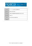
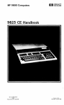
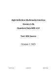
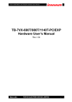
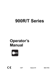
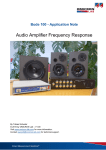
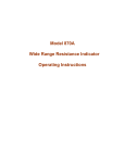
Wireless Home Security System
DIY Kits 15-980PKC2
User Manual
1.
KITS CONTENTS
a.15-980C2
b.15-980K
c.15-980I
d.15-980MT
e. 15-980T
9 Wireless Zones Central Control Unit
Remote Keypad
Wireless PIR Detector
Wireless Door/Window move Detector
Remote Controller
2.
FEATURES
2-1 15-980C2 Central Control Unit
a. 9 wireless Zones, Zone 1~8 is programmable for arm/disarm, Zone 9 is programmed for 24 hours
arming.
b. 2 hard-wired Alarm trigger input(24 hours), 1 DC 12V Alarm output
c. User can define 2 ARM Modes(ARM 1 & ARM2), each mode has 8 wireless detection zones which
can be programmed as “activate” or “bypass” randomly. Each wireless zone can co-operate with
unlimited number of COP wireless alarm accessories. (sensor, detector, etc.)
d. Built-in rechargeable battery, which allows Central Control Unit to work continuously up to 4 hours
when AC power off.
e. Built-in 110dB Siren
f. 16-Character Back-light LCD display
2-2
15-980K
Remote Keypad
a. This Remote Keypad is able to set access code and operate all other functions when it is attached to
the Central Control Unit.
b. This keypad can be apart from the Central Control unit as the remote controller(only controls
ARM1, ARM2, DISARM and PANIC)
c. 20 push buttons (19 programming button and 1 Panic button), can control arm(ARM1 &
ARM2)/disarm, Panic.
d. Low battery LED indication(green light)
e. Power LED indication(red light)
2-3 15-980I
Wireless PIR Detector
a. Provides Pulse-Count Feature to avoid miss triggering. Once the Detector was triggered, the red
LED of detector will flash, but PIR Detector will not transmit signal to the Control Unit unless the
next trigger was detected within 20 seconds from previous trigger.
b. Detecting Distance: 8M, Detecting Angle: 110°
c. Built-in Vibration Detection for self-protect (Jumper ON, see Fig. 3-2-2)
d. Low Battery Indication
2-4 15-980MT Wireless Door/Window move Detector
a. This detector will transmit different signal for “door/window close” or “door/window open” to
Control Unit.
b. This detector can be co-operated with other sensors. For example, gas detector, smoke detector, etc.
c. Built-in Vibration Detection for self-protect (Jumper ON, see Fig.3-3-1)
d. Low Battery Indication (LB LED, green light)
e. Power on Indication (ON LED, red light)
2-5 15-980T
Remote Controller
a. 3 key buttons for Arm/Disarm/Panic wireless remote control
(key button: ON: ARM 1, H: DISARM, T: PANIC)
b. Code-learning function
c. ON LED(red): LED will light while pressing any key of 15-980T
3.
Structure Figures
3-1. 15-980C2
(Fig. 3-1-2)
(Fig. 3-1-3)
Fig. 3-1-1
3-2. 15-980I
1
3-3. 15-980MT
(Fig. 3-3-2)
(Fig. 3-3-1)
(Fig. 3-3-3)
3-4. 15-980T
3-5. 15-980K
(Fig.3-5-1)
(Fig.3-5-2)
2
4.
5.
Preset configuration
4-1 15-980C2
a. Access code:
111
b. In-delay Time: 30 seconds
c. Out-delay Time: 30 seconds
d. Alarm Time:
60 seconds
e. ARM1
zone 1 ~ zone 8(activate)
f. ARM2
zone 1 ~ zone 8 (bypass)
g. 15-980
4-2 Preset Zone for detector
a. 15-980MT
zone 1
b. 15-980I
zone 2
INSTALLATION & TEST
5-1 This Central Control Kits was programmed for ready-to-use. The user may reset the access code if he
prefer other access code to instead.
5-2 CHECKING
Check the DIP switch of all detectors and remote controllers, please be sure all the preset configuration
are the same.(Fig. 3-2-2, Fig. 3-3-1, Fig. 3-4-3)
5-3 INSTALLATION
a. Install all detectors on the proper place. For example, place 15-980MT on the door or window (Fig. 3-32), 15-980I on the wall (Fig. 3-2-1). After complete installation, check battery is in the detector
correctly/turn the power on.
Note: 15-980I PIR Detector is for indoor use. To avoid miss triggering, please do not place the
detector facing abnormal temperature object.
b. Place the battery in the Remove Keypad 15-980K and then put it in to the hole at right side of Central
Control Panel.
c. Fix the hanger on the wall, after that, hang up the Central Control Unit 15-980C2 in the
hanger(Recommend to place this Control Unit at the central of security control kits)
d. Plug AC adaptor cable to 15-980C2, you will hear 2 bi sounds, LCD will displays COP Security(it
means 15-980C2 is in Standby Mode), remember to slide the battery switch to the ON position(Fig. 31-2)
e. Place battery correctly in the battery compartment of Remote Control 15-980T and turn power switcher
on.(Fig.3-4-2)
5-4 TEST
3
Note: Because of the Pulse-Count Feature of PIR detector(please refer to paragraph 2-3, point a), to avoid
miss trigging, you have to away from the detecting area over 20 seconds before test.
Please follows the below test procedure for Function Test
a. Out-Delay Time Test
● Press the ARM button of Remote Control 15-980T or ARM1 button of Remote Keypad 15-980K,
● The Central Control Unit will start Out-Delay Time countdown for 30 seconds(preprogrammed), you
will hear the continuous bi sounds during Out-delay time.
● You will hear a beep sound after Out-delay time, and then the LCD will displays ARM 1 Mode>.
The Security Control System will be in ARM condition.
b. In-Delay Time Test
● Trigger the detector(For example, open the door or window), the red LED of detector will light for 1
second, and you will hear 3 bi sounds. (the detector will transmit signal to Central Control Unit)
● Central Control Unit will start In-delay Time countdown for 30 seconds(preprogrammed).
● After In-delay Time countdown is completed, you will hear the alarm sound from the Siren of Control
Unit for 60 seconds (preprogrammed Alarm time).
● When the Alarm sound stop, the system will be back to ARM condition. LCD will displays, for
example, WL Zone: 1 (if triggered signal was from Wireless Zone 1)
c. 15-980T/15-980K Disarm Function Test
The user may press the DISARM button of 15-980T or buttons #111# of 15-980K (111 is the preset
access code) for disarming.
Note: the Remote Keypad 15-980K will be disable for 60 seconds if the user key in wrong access code
for 3 times.
d. Panic Alarm Test
Before you remove the Remote Keypad as the remote controller, you have to key in the access
code(#111#) and apart the keypad within 5 seconds from the time of enter access code. Otherwise the
Alarm will be triggered.(LCD shows Panic alarm)
e. 15-980I/15-980MT Vibration Detection Test
The detector 15-980I & 15-980MT has built-in vibration detection for self-protect. So when Vibration
Jumper is in ON position (see Fig. 3-2-2, Fig. 3-3-1), the detector will trigger the alarm function once the
detector is vibrated or destroyed.
f. 15-980C2 Vibration Detection Test
Because the Central Control Unit has built-in vibration detection, so once the Control Unit was
vibrated or destroyed, the Control Unit siren will sound and the LCD Display will show “HGSW”.
g. Door-open Signal Test
● When you open the door or window which had been installed detector 15-980MT under DISARM
condition, the Door/Window Detector will transmit door-open-signal to Control Unit. You will hear
Din-Don (Door bell function, please refer to paragraph 6-2-4)
● Every time the Control Unit enters ARM condition, you will hear 4 bi sounds(LCD displays NG)
before countdown In-delay Time, that remind you the door or window has not closed well.
h. Low Battery
This system provides low battery warning function. If any of detectors are in low battery status, when
Control Unit enters ARM condition, you will hear the 4 bi sounds(LCD displays LB) before
countdown In-delay Time.
i. After you have completed the above tests, the Wireless Security System has been successfully installed.
6.
RE-PROGRAMMING
You may also re-program the preset configuration to meet your requirement.
6-1 Change transmission code and zone code
Please follow the below procedure for resetting the codes
4
6-1-1 Change transmission Code of Remote controller 15-980T, Detector 15-980I and 15-980MT
a. Open the battery cover of controller and detector You will find a 10-bit DIP switch of detector and 8bit DIP switch of controller, bit1~bit8 is the 3 levels switch for setting transmission code, bit9~bit10
is the 3 levels switch for setting Zone Code.(Fig. 3-2-2 Fig. 3-3-1 & Fig.3-4-3)
b. Switch bit1~bit8(any combination is available) to set transmission code(up to 6561 code
combination). Please make sure all code combinations set for every detector and controller are the
same.
Note: Because that all the transmission code must be the same. So once you have changed detector’s
transmission code, you have to do Learning-Code(see paragraph 6-1-2) to change 15-980C2’s transmission
code. (also the 15-980K, please refer to paragraph 6-2-3, point A)
6-1-2
a.
b.
c.
d.
e.
f.
g.
h.
Change transmission code for Central Control Unit 15-980C2
Press 15-980K Keypad button #111# (be sure the Keypad is attached on the control unit)
Control Unit LCD Display shows [DISARM], and you will hear 2 bi sounds
Press the Learning Code Button on the side of Control Unit(Fig. 3-1-2) within 20 seconds while LCD
shows [DISARM])
LCD displays [Learning], you will hear 2 bi-bi sounds
Press any button of Remote Controller 15-980T within 5 seconds after the bi sound.
You will hear 4 bi sounds again
LCD will display [Successful] after learning code process is completed.
If the learning code process was wrong, the LCD will display [Fail], then you have to re-program
again follow the above steps.(a~g)
6-1-3 Please refer Fig. 3-6 for setting Detecting Zone.
6-2 15-980C2 Function re-program
Any functions re-programming have to be processed in Function Mode.
*How to enter Function Mode:
a. Key in the access code #111#(original configuration)
b. The LCD will display [DISARM] if the access code is correct
c. Press FUNC. button to enter Function Mode within 20 seconds while LCD shows [DISARM]
d. LCD will display FUNCTION>, then Press ▲or▼button to search one of your demand mode. When
LCD display the correct mode you want, then press ENTER button.
Note: * During re-programming process, any steps have to be completed within 20 seconds, or the status
will go back to previous mode
*You may press CE button if you would like to return to the previous mode during reprogramming operation.
*How to Re-program:
6-2-1 ARM 1 Mode> this mode allows you to program zone 1~8 be activated or bypassed.
a. Press ▲or▼button to search ARM 1 Mode>, and then press ENTER
b. Press ENTER button and then LCD will display ARM 1 > 12345678 (Preset configuration), this
means wireless zone 1,2,3,4,5,6,7,8 are in ARM 1 Mode as the activate zone
c. You may press any figure buttons 1~8 to re-set activate/bypass zone.
d. Please do remember to Press ENTER button to confirm the setting.
6-2-2 ARM 2 Mode> this mode allows you to program zone 1~8 be activated or bypassed.
a. Press ▲or▼button to search ARM 2 Mode>, and then press ENTER
b. Press ENTER button and the LCD will display ARM 2 >_ _ _ _ _ _ _ _ (preset configuration), this
means wireless zone 1,2,3,4,5,6,7,8 are in ARM 2 Mode as the bypass zone.
c. You may press any figure buttons 1~8 to re-set activate/bypass zone.
d. Please do remember to Press ENTER button to confirm the setting.
5
6-2-3 Set Code> This mode provides 2 functions
A. 15-980K Learning Code –
a. Press ▲or▼button to search Set Code>, and then press ENTER
b. Press ENTER button and then LCD displays Code>, the green LED of KeyPad will quick flash for
0.5 second and you will hear 2 bi sounds. This means the learning code process is successfully
completed.
c. Press CE button to return to previous Mode.
B. 15-980K Changes Access Code
a. Follow the above process to enter into Code>
b. Key in the original programmed access code(111), your will hear 2 bi sounds, and then press ENTER
c. LCD displays Newly> , key in the new access code(available for 3~5 digital number) then press
ENTER button
d. LCD displays Again>, then key in the new access code again for confirmation
e. Press ENTER button, you will hear 2 bi-bi sounds and the changing access code is successfully
completed.
6-2-4 Door Bell> Only the wireless zone 1 can be set as doorbell in DISARM condition. In this mode, you
may enable or disable the doorbell function. (Once wireless Zone 1 is triggered, Control Unit will
sound Din-Don)
a. Press ▲or▼button to search Door Dell>, and then press ENTER
b. Press ▲or▼button to select Bell>Enable or Bell>Disable
c. If Press ENTER button after LCD displays Bell>Enable, then the doorbell mode is functioned.
d. If Press ENTER button after LCD displays Bell>Disable, then the doorbell function is disabled
6-2-5 Alarm Time> Alarm time programmable from 0~255 seconds
a. Press ▲or▼button to search Alarm Time>, and then press ENTER
b. Press the figure button for alarm time setting (for example, 60)
c. LCD displays Alarm> 60, Press ENTER button. This means the Alarm time was set as 60 seconds.
6-2-6 In Delay Time > This is for setting In-delay alarm time, time programmable form 0~225 seconds
a. Press ▲or▼button to search In Delay Time>, then press ENTER
b. Press the number button for setting In-Delay Time (for example, 30)
c. LCD displays In Delay >30, press ENTER button. This means the In- Delay Time was set as 30
seconds
6-2-7 Out Delay Time > This is for setting out delay alarm time, time programmable form 0~225 seconds
a. Press ▲or▼button to search Out Delay Time>, then press ENTER
b. Press the number button for setting Out-Delay Time (e.g. 30)
c. LCD displays Out Delay >30, press ENTER button. This means the Out- Delay Time was set as 30
seconds
6-2-8 RESET> this reset function is for reverting to the original preset configuration
a. Press ▲or▼button to search RESET>, then press ENTER
b. LCD display CODE>, press ENTER button
c. Key in access code, and then press ENTER button
d. You will hear 2 bi-bi sounds, all configuration(except the access code) will then be revert to the
original setting
6-2-9 Network Zone>
This is used only with optional software pack. Press CE button to exit.
7. Checking the configuration
6
At Standby Mode, LCD displays COP Security
● Key in correct access code #111# (or the new access code you changed)
● LCD will display [DISARM], you will hear 2 bi-bi sounds
● You may press the ▲▼ button to read the configuration shows on LCD Display and check the current
status of sensors/detectors.
(Note: in this mode, configuration can be read only, not re-programmed)
For Example:
ARM1: 1 2_4_ _7 8
zone 1,2,4,7,8 of ARM1 are activated(the rest is bypassed)
ARM2: _ _3_5 6 7 8
zone 3,5,6,7,8 of ARM2 are activated(the rest is bypassed)
NG:
_ _ _ 5_ _ _
door/window of zone 5 isn’t close well
LB:
_ _3_ _ _ _ _
Detector of zone 3 in low battery condition
In Delay:
30
In-Delay Time 30 seconds
Out Delay: 30
Out-Delay Time 30 seconds
Alarm Time: 60
Alarm Time 60 seconds
WL Zone: _ _3_ _ _ _ _ Wireless Zone 3 was triggered, and this previous trigger was memorized, it will
be erased automatically in next ARM status.
HW Zone: _ _
Hardwire Zone 3 was triggered, and this previous trigger was memorized, it
will be erased automatically in next ARM status.
Bell> Enable
Doorbell function is enabled (Bell>Disable, doorbell function is disabled)
8. SYSTEM EXTENSION
8-1
8-2
8-3
8-4
8-5
8-6
This Wireless Security System can co-operate with full alarm accessory line from COP Security, such
as PIR-15980I wireless PIR detector, 15-980MT wireless door/window move detector, 15-980ST
Remote Control, 15-980ST wireless shake sensor and glass breaking detector, etc… (for more
information, please contact our local dealer or visit our web site: www.cop-security.com)
Wireless Zone 9 is 24 hours arming, which is able to co-operate with 15-980MT door/window detector,
gas detector, smoke detector, etc.
Co-operate with 15-980SL Wireless Siren for additional protection. Once the Central Control Unit
alarm is activated, the Siren is triggered at the same time and will flash & sound continuously until the
alarm is stop.
Co-operate with 15-9802D Wireless Voice Auto Dialer. Once the Alarm is triggered, this Dialer will
automatically dial the pre-set telephone number twice and send the pre-set voice message twice.
Co-operate with 15-980R Wireless Multi-Channel Repeater, that can extent detective distance for
another 30M.
Co-operate with hardwire detector/sensor or external Siren, please refer to Figure 3-1-3 for installation.
9. Trouble Shooting
9-1
15-980I, 15-980MT
a. LED no indication: check the battery and power switch. Be sure battery is placed well, and power
switch is at ON position.
b. Wireless Zone has no transmission:
● Check the Control Unit and all detectors and be sure their transmission code is the same.
● Check the Control Unit and be sure this wireless zone has been programmed in ARM status
● Check and see if the detector was barricaded, or exceed the wireless transmission distance. In this
situation, you may try to re-place it to a proper location.
9-2 15-980K
a. LED no indication: Check the battery, be sure it is placed correctly.
b. No transmission: Place the Remote Keypad in Control Unit and re-process Learning Code.
9-3 15-980C2
a. LED no indication: Check the AC Power Cable and be sure it is well connected.
b. Rechargeable function failed: Check the Battery Switch, be sure it is at the ON position.
7