1
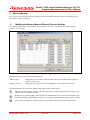
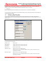
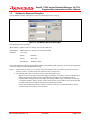
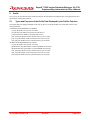
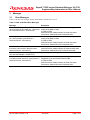
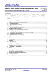
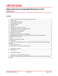
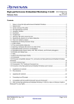
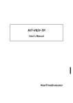
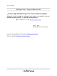
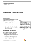
SuperH™ RISC engine Simulator/Debugger V.9.07.01 Supplementary Information for User’s Manual Introduction This document describes how V.9.07.01 of the SuperH™ RISC engine Simulator/Debugger differs from V.9.07.00. Before using the simulator/debugger, carefully read this document, the SuperH™ RISC engine Simulator/Debugger User’s Manual, and the online help for the SuperH™ RISC engine Simulator/Debugger. Contents 1. 1.1 1.2 1.3 Memory Mapping .............................................................................................................................. 2 Modifying the Memory Map and Memory Resource Settings........................................................... 2 Set Memory Map Dialog Box ............................................................................................................ 3 Set Memory Resource Dialog Box.................................................................................................... 5 2. Profile ................................................................................................................................................ 6 2.1 Types and Purposes of the Profile Data Displayed by the Profiler Function.................................... 6 3. Messages.......................................................................................................................................... 7 3.1 Error Messages................................................................................................................................. 7 REJ10J1892-0100/Rev.1.00 June 2008 Page 1 of 8 SuperH™ RISC engine Simulator/Debugger V.9.07.01 Supplementary Information for User’s Manual 1. Memory Mapping In V.9.07.01, the specification of memory mapping for the SH-2A has been changed. This section describes the new specification of memory mapping. 1.1 Modifying the Memory Map and Memory Resource Settings The [Memory] tabbed page in the [Simulator System] dialog box is used to set and modify the memory map and memory resource settings. Figure 1.1 Simulator System Dialog Box (Memory Tab) The following items can be specified in this dialog box. [Memory Map] Displays the types of memory, addresses where each starts and ends, data bus width, and number of access cycles. [Memory Resource] Displays the access type and start and end addresses of the current memory resource. The following buttons are used to alter [Memory Map] (add, modify, or delete entries). Add items to [Memory Map]. Clicking on this button opens the [Set Memory Map] dialog box (figure 1.2), in which an item can be added to the map. Modify an item in [Memory Map]. Select the item to be modified in the list box and click on this button. This opens the [Set Memory Map] dialog box (figure 1.2), in which the selected memory map item can be modified. Delete an item from [Memory Map]. Select the item to be deleted in the list box and click on this button. REJ10J1892-0100/Rev.1.00 June 2008 Page 2 of 8 SuperH™ RISC engine Simulator/Debugger V.9.07.01 Supplementary Information for User’s Manual In [Memory Map], the start address, end address, memory type, data bus width, number of cycles for reading, and number of cycles for writing are displayed, in that order. The memory types are as follows: • SH2A-FPU ROM (internal ROM), RAM (internal RAM), EXT (external memory), I/O (internal I/O), EEPROM Click on the [OK] or [Apply] button to store the modified settings. Click on the [Cancel] button to close this dialog box without modifying the settings. 1.2 Set Memory Map Dialog Box The [Set Memory Map] dialog box specifies the memory map of the target CPU. The contents of this dialog box depend on the target CPU. The simulator/debugger uses the data specified in this box to calculate numbers of cycles for memory access. Figure 1.2 Set Memory Map Dialog Box The following items are specified: [Memory type] Memory type [Begin address] Address where the area of the given type starts. [End address] Address where the area of the given type ends. [Data bus size] Memory data bus width [Read state count] When the memory type is ROM: Latency When the memory type is not ROM: Number of cycles (“states”) for read access to the specified type of memory [Write state count] When the memory type is ROM: Throughput When the memory type is not ROM: Number of cycles (“states”) for write access to the specified type of memory REJ10J1892-0100/Rev.1.00 June 2008 Page 3 of 8 SuperH™ RISC engine Simulator/Debugger V.9.07.01 Supplementary Information for User’s Manual Notes: 1. In terms of the memory resources of the SH2A-FPU, note the following. - In the memory areas that are fixed as ROM or RAM, selection of another memory type or allocation in two or more ranges is not possible. The memory areas that are fixed as ROM and RAM are given below. - Area ROM Address Range 0x00000000 - 0x01FFFFFF RAM 0xFFF80000 - 0xFFFBFFFF Remark When the internal ROM has been enabled No addresses in reserved areas can be specified. The reserved areas are given below. Area Reserved Address Range 0x20000000 - 0x21FFFFFF Remark When the internal ROM has been enabled 0x84000000 - 0xE7FFFFFF - - Memory can only be allocated on 8-kbyte boundaries. If memory is allocated to an address range that does not have 8-kbyte boundaries, the boundaries will be adjusted to 8-kbyte boundaries that encompass the specified range. Numbers of cycles for access to the areas fixed as ROM and RAM are as follows. Area ROM RAM Number of Cycles for Reading (Latency) 1 or 2 Number of Cycles for Writing (Throughput) 1 to 4 1 to 4 2. The memory map setting for area that is allocated to a system memory resource cannot be deleted or modified. Start by deleting the system memory-resource allocation on the [Memory] tab of the [Simulator System] dialog box, then delete or modify the memory map setting. Clicking on the [OK] button stores the modified settings. Clicking on the [Cancel] button closes the dialog box without modifying the settings. REJ10J1892-0100/Rev.1.00 June 2008 Page 4 of 8 SuperH™ RISC engine Simulator/Debugger V.9.07.01 Supplementary Information for User’s Manual 1.3 Set Memory Resource Dialog Box The [Set Memory Resource] dialog box is used to set and modify memory resources. Figure 1.3 Set Memory Resource Dialog Box The following items are specified: [Begin Address] Address where the memory area to be allocated starts [End Address] Address where the memory area to be allocated ends [Attribute] Access type [Read] Read only [Write] Write only [Read/Write] Readable/writable Click on the [OK] button after specifying [Begin Address], [End Address], and [Attribute]. Click on the [Cancel] button to close the dialog box without modifying the settings. Notes: 1. When a memory resource is set, memory in the host computer will be used. If the user allocates excessive memory resources, operation of the host computer will be extremely slow. 2. The following notes apply to memory resources for the SH2A-FPU series. - Memory resources can only be allocated on 8-kbyte boundaries. If a memory resource is allocated to an address range that does not have 8-kbyte boundaries, the boundaries will be adjusted to 8-kbyte boundaries that encompass the specified range. Accordingly, address ranges of attributes are allocated on 8-kbyte boundaries. When a memory resource does not take up a full 8-kbyte range, the memory that is actually used must be within the range defined in the hardware manual. - Do not clear the default allocation of a memory resource as I/O area. If such an allocation is cleared, operation of the cache memory will be incorrect. REJ10J1892-0100/Rev.1.00 June 2008 Page 5 of 8 SuperH™ RISC engine Simulator/Debugger V.9.07.01 Supplementary Information for User’s Manual 2. Profile In V.9.07.01, the specification of the profiler function for the SH-2A has been changed. This section describes the new specification of the profiler function. 2.1 Types and Purposes of the Profile Data Displayed by the Profiler Function The profile data to be displayed depends on the CPU. In the case of the SH2A-FPU, the profile data consists of the items listed below. (a) When the internal ROM has been disabled: [Cycle] (the number of cycles for execution), [ICache miss] (the number of instruction cache misses), [OCache miss] (the number of operand cache misses), [Ext_mem] (the number of times external memory was accessed), [I/O_area] (the number of times internal I/O area was accessed), [Int_mem] (the number of times internal memory was accessed) (b) When the internal ROM has been enabled: [Cycle] (the number of cycles for execution), [ROM ICache miss] (the number of instruction ROM cache misses), [ROM OCache miss] (the number of operand ROM cache misses), [Ext_mem] (the number of times external memory was accessed), [I/O_area] (the number of times internal I/O area was accessed), [Int_mem] (the number of times internal memory was accessed) REJ10J1892-0100/Rev.1.00 June 2008 Page 6 of 8 SuperH™ RISC engine Simulator/Debugger V.9.07.01 Supplementary Information for User’s Manual 3. 3.1 Messages Error Messages Table 3.1 lists the error messages that have been added or modified in V.9.07.01. Table 3.1 New or Modified Error Messages Message Incorrect memory type. The specified address range includes an area fixed as rr. (Area fixed as rr: 0xmmmmmmmm - 0xnnnnnnnn) Description An attempt was made to assign another memory type to an area fixed as ROM or RAM. rr: ROM or RAM 0xmmmmmmmm: Address where the fixed area starts 0xnnnnnnnn: Address where the fixed area ends Allocating two or more ranges in an area fixed An attempt was made to allocate two or more ranges in an area fixed as ROM or RAM. as rr is not possible. (Area fixed as rr: 0xmmmmmmmm - 0xnnnnnnnn) rr: ROM or RAM 0xmmmmmmmm: Address where the fixed area starts 0xnnnnnnnn: Address where the fixed area ends Incorrect address. The specified address range An attempt was made to map memory to a reserved area. includes a reserved area. (Reserved area: 0xmmmmmmmm: Address where the reserved area starts 0xmmmmmmmm - 0xnnnnnnnn) 0xnnnnnnnn: Address where the reserved area ends I/O area does not exist. No memory has been mapped as the I/O area. (I/O area: 0xF0000000 - 0xF5FFFFFF) Incorrect address. The specified address range An attempt was made to map memory beyond the is outside an area fixed as rr. (Area fixed as rr: boundaries of an area fixed as ROM or RAM. 0xmmmmmmmm - 0xnnnnnnnn) rr: ROM or RAM 0xmmmmmmmm: Address where the fixed area starts 0xnnnnnnnn: Address where the fixed area ends REJ10J1892-0100/Rev.1.00 June 2008 Page 7 of 8 SuperH™ RISC engine Simulator/Debugger V.9.07.01 Supplementary Information for User’s Manual Notes regarding these materials 1. 2. 3. 4. 5. 6. 7. 8. 9. 10. 11. 12. 13. This document is provided for reference purposes only so that Renesas customers may select the appropriate Renesas products for their use. Renesas neither makes warranties or representations with respect to the accuracy or completeness of the information contained in this document nor grants any license to any intellectual property rights or any other rights of Renesas or any third party with respect to the information in this document. Renesas shall have no liability for damages or infringement of any intellectual property or other rights arising out of the use of any information in this document, including, but not limited to, product data, diagrams, charts, programs, algorithms, and application circuit examples. You should not use the products or the technology described in this document for the purpose of military applications such as the development of weapons of mass destruction or for the purpose of any other military use. When exporting the products or technology described herein, you should follow the applicable export control laws and regulations, and procedures required by such laws and regulations. All information included in this document such as product data, diagrams, charts, programs, algorithms, and application circuit examples, is current as of the date this document is issued. Such information, however, is subject to change without any prior notice. Before purchasing or using any Renesas products listed in this document, please confirm the latest product information with a Renesas sales office. Also, please pay regular and careful attention to additional and different information to be disclosed by Renesas such as that disclosed through our website. (http://www.renesas.com) Renesas has used reasonable care in compiling the information included in this document, but Renesas assumes no liability whatsoever for any damages incurred as a result of errors or omissions in the information included in this document. When using or otherwise relying on the information in this document, you should evaluate the information in light of the total system before deciding about the applicability of such information to the intended application. Renesas makes no representations, warranties or guaranties regarding the suitability of its products for any particular application and specifically disclaims any liability arising out of the application and use of the information in this document or Renesas products. With the exception of products specified by Renesas as suitable for automobile applications, Renesas products are not designed, manufactured or tested for applications or otherwise in systems the failure or malfunction of which may cause a direct threat to human life or create a risk of human injury or which require especially high quality and reliability such as safety systems, or equipment or systems for transportation and traffic, healthcare, combustion control, aerospace and aeronautics, nuclear power, or undersea communication transmission. If you are considering the use of our products for such purposes, please contact a Renesas sales office beforehand. Renesas shall have no liability for damages arising out of the uses set forth above. Notwithstanding the preceding paragraph, you should not use Renesas products for the purposes listed below: (1) artificial life support devices or systems (2) surgical implantations (3) healthcare intervention (e.g., excision, administration of medication, etc.) (4) any other purposes that pose a direct threat to human life Renesas shall have no liability for damages arising out of the uses set forth in the above and purchasers who elect to use Renesas products in any of the foregoing applications shall indemnify and hold harmless Renesas Technology Corp., its affiliated companies and their officers, directors, and employees against any and all damages arising out of such applications. You should use the products described herein within the range specified by Renesas, especially with respect to the maximum rating, operating supply voltage range, movement power voltage range, heat radiation characteristics, installation and other product characteristics. Renesas shall have no liability for malfunctions or damages arising out of the use of Renesas products beyond such specified ranges. Although Renesas endeavors to improve the quality and reliability of its products, IC products have specific characteristics such as the occurrence of failure at a certain rate and malfunctions under certain use conditions. Please be sure to implement safety measures to guard against the possibility of physical injury, and injury or damage caused by fire in the event of the failure of a Renesas product, such as safety design for hardware and software including but not limited to redundancy, fire control and malfunction prevention, appropriate treatment for aging degradation or any other applicable measures. Among others, since the evaluation of microcomputer software alone is very difficult, please evaluate the safety of the final products or system manufactured by you. In case Renesas products listed in this document are detached from the products to which the Renesas products are attached or affixed, the risk of accident such as swallowing by infants and small children is very high. You should implement safety measures so that Renesas products may not be easily detached from your products. Renesas shall have no liability for damages arising out of such detachment. This document may not be reproduced or duplicated, in any form, in whole or in part, without prior written approval from Renesas. Please contact a Renesas sales office if you have any questions regarding the information contained in this document, Renesas semiconductor products, or if you have any other inquiries. 2008. Renesas Technology Corp., All rights reserved. REJ10J1892-0100/Rev.1.00 June 2008 Page 8 of 8