1
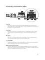
CPU, Chassis & AGP cooling Fan
connectors - JP3, JP5 & J1
The main board provides three onboard 12V cooling
fan power connectors. Depending on the fan maker,
the wiring and plug may be different. The red wire
should be connected to +12V and black wire should
be connected to ground (GND).
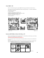
Wake-On-LAN Connector - J14
Attach a 3-pin connector from the LAN card which
supports the Wake-On-LAN (WOL) function. This
function lets users wake up the connected system
through the LAN card.
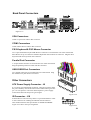
Enhanced IDE, Floppy and COM2
connectors
The main board shipped with one 40-pin ribbon cable
for IDE H.D.D , one 34-pin ribbon cable for F.D.D and
one 10-pin ribbon cable for COM2. Ribbon cables should
always be connected with the red stripe on the Pin 1 side
of the connector.
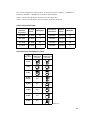
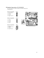
CD Audio Connectors
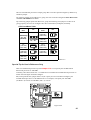
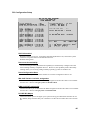
Figure 2-36
SJ1: 1 = Left Channel
2 = Ground
3 = Ground
4 = Right Channel
SJ2: 1 = LAUX
2 = Ground
3 = Ground
4 = RAUX
SJ3: 1 = Ground
2 = Right Channel
3 = Ground
4 = Left Channel
Figure 2-37
22