1
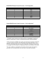
MP-204D
Digital/Analog Stereo Monitor Panel
Videoquip Research Limited
595 Middlefield Road, Unit #4
Scarborough, Ontario, Canada. MIV 3S2
(416) 293-1042
1-888-293-1071
www.videoquip.com
1
Videoquip MP-204D User Manual
The MP-204D is a digital/analog monitoring panel, allowing either analog or
(using an optional plug-in board) digital audio (AES/EBU) stereo signals to be
monitored via internal speakers, or headphones. Front panel metering is
provided with a bar graph type LED display for both analog and digital signals.
As described above, the digital audio board is available as an optional plug-in
device. If it is installed, the MP-204D will sense the board, and the front panel
input selection switch labelled DIGITAL will allow the board to be used. If the
board is not installed, the MP-204D will function as a stereo analog monitor, and
the DIGITAL switch will be inactive. When the red LED indicator associated with
the DIGITAL switch is illuminated as the switch is being pressed, the MP-204D
has found the digital audio board. This will allow either digital audio input labelled
A or B, to be monitored.
Two stereo analog signals or two stereo digital audio signals may be connected
via the rear panel, and front panel switching allows either set of inputs to be
selected. In addition, a line output is available on the rear panel via balanced
XLR connectors for left and right. This allows the selected input signal to be
connected to a line level input device such as a power amplifier, if desired.
The MP-204D supports four output mode selections as monitoring choices. They
are STEREO, LEFT ONLY, RIGHT ONLY, and MONO. Four mode switches
located on the front panel with associated LED indicators allow each mode to be
selected easily for monitoring convenience. Further, each pair of inputs, either
analog or digital may have a unique output mode. The firmware of the MP-204D
retains the mode associated with that input unless it has been modified.
For example, Analog Input A may be set to monitor in STEREO, and Analog
Input B may be set to monitor in MONO. Switching between A and B will retain
that selection until it has been changed. The digital audio inputs function
accordingly as well. Upon power-down of the unit, the last monitored input with
its associated output mode selection (and level if it is an analog input) will be
restored upon power-up.
A stereo headphone jack is available on the front panel, allowing the signal to be
monitored via a suitable pair of headphones. In normal operation, the front panel
speakers are disabled when headphones are inserted. It is also possible to install
a set of internal jumpers (J9, J11) on the main circuit board just above the
external speaker connector, which prevents the internal speakers from being
disabled when headphones are inserted.
2
A front panel volume control is also available which affects only the
headphone/speaker volume. The front panel meter and line out are independent
of the internal monitor power amplifier, and will function normally with the volume
control set to minimum.
Each digital audio input (A and B) supports both AES3 (XLR) balanced inputs,
and AES3-ID (BNC) unbalanced inputs, for maximum versatility without requiring
external switching. Both input types are considered professional with regard to
channel status information, which is of no concern to the MP-204D since it
recovers and monitors only audio signals.
It is therefore possible to connect an S/PDIF (consumer) source as well, with a
BNC to Phono (RCA) adapter, since AES3-ID and S/PDIF both support a 75Ohm transmission line impedance. A slide switch associated with each digital
audio input is provided to select the incoming format. To monitor an S/PDIF
digital audio signal, simply connect the correct BNC to RCA adapter, and set the
slide switch to the AES3-ID position for that input.
As described, two stereo analog inputs are available, Inputs A and B.The
sensitivity of these analog inputs can be adjusted via the front panel, and saved
in on-board EEPROM. Analog Input A can be set for example to 0 dBu, and
Analog Input B could be set to +8 dBu. When switching back and forth between
inputs, the gain will be electronically altered for each one to accommodate the
desired sensitivity. The digital audio inputs however, default to the equivalent of
+0 dBu or 0 dBFS, to ensure that the front panel metering is always calibrated.
This is a direct result of the fact that operating levels are interpreted differently in
analog and digital audio. Consequently, they require a somewhat different
metering methodology. The 0 dB LED represents the nominal operating level
when monitoring an analog signal, where the choices available are –10 dBu, 0
dBu, +4 dBu, and +8 dBu. As described, the two analog inputs may be set to one
of these four standard operating levels, independently.
The digital inputs are calibrated by connecting a 1 KHz, 0 dBFS sinewave from
an AES/EBU digital audio test generator to either Digital Input A or B, and
selecting the chosen input from the front panel. The DIGITAL indicator LED
should be illuminated and the appropriate A or B indicator LED should therefore
be illuminated according the source of the digital audio input signal.
On the main board are two rotary potentiometers R97 and R98 labelled Digital
Left and Digital Right Adjust. The analog line outputs of the MP-204D should be
connected to the analog line inputs of a test device capable of reading and
displaying the level in dBu of an analog sine wave signal. Adjust the
potentiometers with a screwdriver until the 0 dB LED is illuminated, and the
analog output level is 0 dBu.
3
The output mode select switches are used to indicate the operating level and
incorporate dual color indicators, red and green. The red LED indicates the
current output mode, and the green LED indicates the current operating level
selection for the selected input. In order to prevent inadvertent changes to the
operating level for Analog Input A or Input B, the selection of either level is
accomplished via a recessed front panel switch labelled SET LEVEL.
To set the operating level of either Analog Input A or Input B
1) Ensure that the DIGITAL indicator is OFF by selecting the pushbutton
alternately until the LED is off. Note that if the digital audio board is not
installed, the analog inputs only will be available by default.
2) Select the Analog A Input via the pushbutton. The indicator will be illuminated.
3) The selection of a standard monitoring level is accomplished by inserting a
small thin screwdriver or similar object in the access hole labelled SET
LEVEL. Push and hold the internal recessed switch with the screwdriver while
at the same time pressing the desired level pushbutton. The green indicator
shows which level is being selected and the selected level will be saved
automatically.
4) Repeat as needed for the Analog B input. Ensure that the Analog B indicator
is illuminated for that input before changing the level.
This procedure applies only to the analog inputs. Additionally, a CLIP LED will
illuminate when the analog signal level exceeds + 20 dBu. When monitoring a
digital audio signal however, the 0 dB LED is calibrated to represent a full-scale
(0 dBFS) digital audio input signal, similar to most digital audio meters, including
the Videoquip Research VP – 2D.
Since internal electronic switching is performed, the firmware of the MP-204D will
not allow the operating level of a digital input signal to be varied in the same way
that an analog signal level may be varied. This ensures that the 0 dB LED will
always represent a 0 dBFS full-scale static signal.
The meter is based on analog signal processing circuitry, and approximates a
PPM ballistic response. Under dynamic conditions with musical content, it is
possible for occasional illumination of the +1 dB LED to be observed. This
usually indicates that a high crest factor for that musical phrase will cause the
meter circuitry to slightly over-range, although the MP-204D cannot accurately
process a true digital “over” condition.
4
For a full digital meter incorporating digital signal processing circuitry (DSP), the
“over” condition would usually be considered a given number of consecutive fullscale samples. This could possibly indicate that the signal was slightly clipped in
a manner similar to analog clipping. In digital audio however, once saturation has
been reached, no more codes exist to fully represent that input sample amplitude
for a given digital word length. A consecutive number of such samples are
generally considered an “over” condition, which the DSP can easily accumulate
and report to the user via a dedicated “over” indicator.
In addition, the front panel meter gain only may be trimmed with recessed
potentiometers just to the left of each LED array for left and right channel.
To calibrate the meter for 0 dB with a known analog input source
1) Connect a balanced analog audio sinewave source set to 1 KHz @ 0 dBu to
the left and right inputs of either Input A or Input B.
2) Select the Analog A Input Source via the front panel pushbuttons.
3) Ensure that the operating level is set to 0 dBu, for that input. This procedure
is discussed on the previous page (4) of this manual.
4) Using a small flat-blade screwdriver, adjust the recessed front panel
potentiometers for left and right channel until the 0 dB LED indicator is
illuminated.
MP-204D Control Scheme
The parallel remote control and serial remote control protocol for host computer
communications with the MP-204D is described. The monitor panel can be
remotely controlled with either of the following.
1) Local Parallel Control which parallels the front panel switch array and
provides the same features as the front panel, including input selection and
output mode selection. Note that operating level selections are not available
by remote control, for either parallel or serial control. This was done as a
safety precaution. The pin configuration is shown on page 10.
Additionally, a mute input is available as a momentary closure, which mutes
the active input, and flashes the led of the corresponding input switch LED
when it is activated. This is available only on the rear panel DB-9F parallel
remote connector.
2) The RS-422 serial remote control input, at 9600 Baud, No Parity, 8 Data, 1
Stop Bit. When RS-422 remote control is desired, this is available as a rear
panel DB-9F connector.
5
MP204-AD Serial Remote Protocol - Description
The MP-204D does not include any provision for a logical address as would be
found in a daisy chained multi-drop environment. The protocol consists of a
header byte, a message byte, and an optional checksum byte.
The MP-204D provides host communications at 9600 Baud, no parity, 8 data
bits, and 1 stop bit. The protocol is a constant length (3 bytes) protocol, with all
bytes required, although don’t care data (the value can be from anything from
00h to 0FFh) can be sent for each unnecessary checksum data value.
All message types, except type 0AH (Get Digital Card Status), will echo the three
bytes as sent to it, as confirmation that it is connected to the host and that
communications has been established. A special message type can be used as
an “Alive Inquiry” <0BH>, which simply returns or echoes the received bytes with
no internal processing, to test communications with the MP-204D.
Protocol Format
Header
Message Type
Checksum
<AAH>
00H to 0BH
Optional (or 00H to 0FFH)
Defined Message types for the MP-204D are as follows, in hexadecimal notation
0x00H - Disable checksum processing. This message type forces the MP-204D
to ignore checksum data as received, although a dummy checksum must be sent
as a don’t care value, since the protocol is constant length.
0x01H - Enable checksum processing. This message type forces the
MP-204D to receive a correct checksum of the received data, before updating
the switch settings. This serves to minimize the effect of communication line
errors that would affect the data. The received checksum must match the
checksum calculated by the MP-204D before the new setting is updated. If the
received and calculated checksum values do not agree, then that transmission is
ignored as far as an update is concerned, however the command is echoed to
the host.
0x02H - Select analog input A
0x03H - Select analog input B
0x04H - Select digital input A. If the digital card is not installed, the switch
settings will not update.
6
0x05H - Select digital input B. If the digital card is not installed, the switch
settings will not update.
0x06H - Select stereo output mode.
0x07H - Select left only output mode.
0x08H - Select right only output mode.
0x09H - Select mono sum output mode.
0x0AH - Get Digital Card Status. Determine the status of the digital card, i.e.,
installed or not installed. The firmware will respond with the following data after
receipt of this message.
AA 0A 00 – Digital Card is installed
AA 0A FF – Digital Card is not installed
0x0BH - Alive Inquiry. This message type will simply return (echo) the message
with no internal action on the part of the MP-204D, as confirmation of alive
status.
Checksum Byte
If message type 01H has been sent to the MP-204D in a previous transmission, it
is necessary for a correct checksum byte to be sent as the last byte in all other
transmissions until it is disabled by sending message type 00H. The MP-204D
has an internal EEPROM device to store switching settings as well as the
checksum required status. This makes it possible to retain the need for
checksum processing, even after a new power-up cycle. The status is updated in
EEPROM after receipt of message types either 00H or 01H.
The checksum is calculated as the two’s complement XOR sum of the first 2
bytes of the transmission, not including byte 3, the actual checksum byte.
7
Example1
If checksum processing has been enabled using message type 01H, then the
following would describe the switch update messages from 0x02H to 0x09H.
Byte 1
Byte 2
Byte 3
<0xAAH>
<0x02H> to <0x09>
<valid checksum>
This will update the switches as defined previously. The checksum can be sent
as any value from 00H to 0FFH if checksum processing has been disabled.
Example2
To disable checksum processing, send the following command
<0xAAH>
<00H>
<00H> (no checksum)
To enable checksum processing, send the following command
<0xAAH>
<01H>
<00H> (no checksum)
The Alive Inquiry is selected as follows
<0xAAH>
<0xAAH>
<0BH>
<0BH>
<00H> (no checksum, sent as don’t care)
<5FH> (with checksum enabled)
To select Analog Input A, send the following
<0xAAH>
<0xAAH>
<02H>
<02H>
<00H> (no checksum, sent as don’t care)
<58H> (with checksum enabled)
Note that for test purposes, the Windows 95/98 Calculator Accessory will support
hexadecimal and logical operations and arithmetic functions and can be used to
quickly determine a two’s complement value checksum. An application program
written to control the MP-204D would perform this checksum calculation as part
of the transmission to the unit, in real time.
The MP-204D will echo the command string sent to it for the message types
defined above. Reception of any other undefined message types will cause the
MP-204D to ignore the transmission and return nothing to the host.
Note that on-board EEPROM is used to store checksum required/not required
status, as well as to save mode/analog level settings and restore power up saved
settings.
8
MP-204D Specifications
Power Requirements
115 VAC, 60 Hz or 230 VAC, 50Hz, 12W
Analog Audio Inputs
Input Impedance
Input Signal Level
Maximum Input Level
Input Connectors
Common Mode Rejection
40 Kohms balanced, 20 Kohms unbalanced
-10, 0, +4, or +8 dBu (front panel selected)
+24 dBu, front panel CLIP indicator at +21 dBu
XLR-3F and ¼“TRS, x 4
-60 dB @ 60Hz
Analog Audio Outputs
Output Impedance
Output Signal Level
Output Connectors
66 Ohms balanced
0 dBu nominal, +24 dBu max
XLR-3M, x 2
Digital Audio Inputs
AES3
Input Impedance
Input Connectors
switch selectable, rear panel
110 Ohms, transformer isolated
XLR-3F, x 2
AES3-ID
Input Impedance
Input Connectors
switch selectable, rear panel
75 Ohms
BNC Panel Mount Female, x 2
Amplifier
Power Output
Frequency Response
THD + Noise
Hum and Noise
4 Watts RMS per channel into 8 Ohms
20 Hz to 20 KHz +/- 1 dB
0.1% or less, full bandwidth
-70 dBu
Speakers
Standard
Magnetically Shielded
3 x 5 inch oval, 4 Watts @ 8 Ohms
3 x 5 inch oval, 4 Watts @ 8 Ohms
Remote Control
Parallel Remote
Serial Remote
DB-9F (pull down to ground)
RS-422, DB-9F
9600 Baud, No Parity, 8 Data, 1 Stop
Checksum Enabled or Disabled
9
RS-422 DB-9F Remote Control Connector – Pin Configuration
Pin Number
1
2
3
4
5
6
7
8
9
Function
N.C.
TXDRXD+
GND
N.C.
GND
TXD+
RXDN.C.
Parallel DB-9F Remote Control Connector – Pin Configuration *
Pin Number
1
2
3
4
5
6
7
8
9
Function
MONO (SUM)
LEFT ONLY
DIGITAL
A INPUT
GND
RIGHT ONLY
STEREO
B INPUT
MUTE **
* All parallel remote functions are implemented by a momentary connection of
that pin to ground (pin 5), which is recognized by the MP-204D immediately.
** The mute input is available only on the rear panel remote connector. Note that
when the mute input is active, the LED indicator associated with either A, B or
DIGITAL switches will flash as a reminder of that state. If Analog A was selected
for example, the LED indicator for Analog A will flash for the duration of the mute.
The mute condition is sustained for the duration that the mute input (pin 9) is
grounded, and is released when the mute input is removed from ground.
10
Warranty
Videoquip Research Limited (VRL) warrants the MP-204D for a period of 2 (two)
years from the date of shipment from the factory, to be free of defects in
workmanship and material under normal use and service. This warranty is void if
failure is due to abnormal use or modification, or if serial numbers have been
tampered with. VRL’s liability is limited to the repair or replacement of this unit, or
to a sales credit, and the warranty action taken is at the sole discretion of VRL.
Any warranty claims must be received in writing by VRL before the expiration of
the two year period. Warranty coverage does not include shipping costs. This
warranty is in lieu of all other warranties, expressed or implied, and all other
obligations or liabilities of Videoquip Research Limited.
11