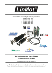
1
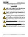
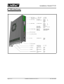
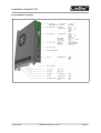
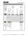
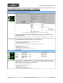
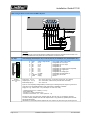
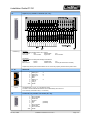
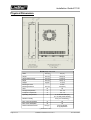
Documentation for installing the following Drives: - E1100-CO (-HC, -XC) E1100-DN (-HC, -XC) E1100-RS (-HC, -XC) E1130-DP (-HC, -XC) E1100-GP (-HC, -XC) Drive Data Sheet & Installation Guide Eine Deutsche Version kann unter http://www.linmot.com bezogen werden! Please visit http://www.linmot.com to check for the latest version of this document! Installation Guide E1100 © 2014 NTI AG This work is protected by copyright. Under the copyright laws, this publication may not be reproduced or transmitted in any form, electronic or mechanical, including photocopying, recording, microfilm, storing in an information retrieval system, not even for didactical use, or translating, in whole or in part, without the prior written consent of NTI AG. LinMot® is a registered trademark of NTI AG. Note The information in this documentation reflects the stage of development at the time of press and is therefore without obligation. NTI AG reserves itself the right to make changes at any time and without notice to reflect further technical advance or product improvement. Document version 3.19a / FM,Ro / March 2014 Page 2 of 27 Installation Guide E1100 10/04/2014 NTI AG/ LinMot/ Installation Guide E1100 Table of Content IMPORTANT SAFETY NOTES FOR E1100 DRIVES....................................................4 SYSTEM OVERVIEW.....................................................................................................5 E1100 INTERFACES......................................................................................................6 E1100-GP (-LC/HC/XC).............................................................................................6 E1100-CO/DN/RS (-LC/HC/XC).................................................................................7 E1130-DP (-LC/HC/XC)............................................................................................. 8 FUNCTIONALITY............................................................................................................9 E1130-DP(-HC, -XC) FUNCTIONS AND WIRING.......................................................10 E1100-GP (-HC, -XC) FUNCTIONS AND WIRING......................................................11 E1100-CO (-HC, -XC), -DN (-HC, -XC), -RS (-HC, -XC) FUNCTIONS AND WIRING.12 POWER SUPPLY AND GROUNDING.........................................................................13 DESCRIPTION OF THE CONNECTORS / INTERFACES...........................................14 ERROR CODES............................................................................................................21 PHYSICAL DIMENSION...............................................................................................22 POWER SUPPLY REQUIREMENT..............................................................................23 REGENERATION OF POWER / REGENERATION RESISTOR.................................23 ORDERING INFORMATION.........................................................................................24 INTERNATIONAL CERTIFICATIONS..........................................................................24 SAFETY NOTES FOR THE INSTALLATION ACCORDING TO UL...........................25 DRIVE CLASSIFICATION ACCORDANCE WITH THE NEW.....................................25 MACHINERY DIRECTIVE EN ISO 13849-1.................................................................25 DECLARATION OF CONFORMITY CE-MARKING....................................................26 CONTACT ADDRESSES.............................................................................................27 NTI AG, LinMot Installation Guide E1100 10/04/2014 Page 3/27 Installation Guide E1100 Important Safety Notes for E1100 Drives CAUTION! In order to assure a safe and error free operation, and to avoid severe damage to system components, all system components must be directly attached to a single ground bus that is earth or utility grounded (see chapter Power Supply and Grounding). Each system component should be tied directly to the ground bus (star pattern), rather than daisy chaining from component to component. (LinMot motors are properly grounded through their power cables when connected to LinMot drives) (see chapter Power Supply and Grounding). All connectors must not be connected or disconnected while DC voltage is present. Do not disconnect system components until all LinMot drive LEDs have turned off. (Capacitors in the power supply may not fully discharge for several minutes after input voltage has been disconnected). Failure to observe these precautions may result in severe damage to electronic components in LinMot motors and/or drives. Do not switch Power Supply DC Voltage. All power supply switching and E-Stop breaks should be done to the AC supply voltage of the power supply. Do not connect or disconnect the motors from drives with voltage present. Wait to connect or disconnect motors until all LinMot drive's LEDs have turned off. (Capacitors may not fully discharge for several minutes after power has been turned off). Failure to observe these precautions may result in severe damage to electronic components in LinMot motors and/or drives. Page 4 of 27 Installation Guide E1100 10/04/2014 NTI AG/ LinMot/ Installation Guide E1100 System Overview Typical Servo System E1100-XX: Drive, Linear Motor and Power Supply. NTI AG, LinMot Installation Guide E1100 10/04/2014 Page 5/27 Installation Guide E1100 E1100 Interfaces E1100-GP (-LC/HC/XC) Page 6 of 27 Installation Guide E1100 10/04/2014 NTI AG/ LinMot/ Installation Guide E1100 E1100-CO/DN/RS (-LC/HC/XC) NTI AG, LinMot Installation Guide E1100 10/04/2014 Page 7/27 Installation Guide E1100 E1130-DP (-LC/HC/XC) Page 8 of 27 Installation Guide E1100 10/04/2014 NTI AG/ LinMot/ Installation Guide E1100 NTI AG, LinMot E1100-RS-HC E1100-RS-XC E1100-CO E1100-CO-HC E1100-CO-XC E1100-DN E1100-DN-HC E1100-DN-XC E1130-DP E1130-DP-HC E1130-DP-XC E1100-GP E1100-GP-HC E1100-GP-XC Supply Voltage Motor Supply 72VDC (24...85VDC) (30..85VDC for UL) Logic Supply 24VDC (22...26VDC) Motor Phase Current 8A peak / 6A rms 15A peak / 9A rms 25A peak / 12A rms Controllable Motors LinMot P01-23x… P01-37x… P01-48x… DC Motors Brushless DC / EC Motors Command Interface Easy Step Application Layer (X4-IOs) Cmd Tab IO Interface (X6-IOs) RS232 up to 115.2 kBaud RS485 up to 115.2 kBaud CANOpen up to 1MBaud DeviceNet 125, 250, 500 kBaud PROFIBUS DP up to 12 MBaud Programmable Motion Profiles (Curves) Up to 99 Motion Profiles Up to 8110 Curve Points Programmable Command Table Command Table with up to 255 entries External Position Sensor Incremental RS422 up to 2 MHz Sin/Cos 1Vpp up to 10 kHz Synchronisation Master Encoder In/Out RS422 up to 2 MHz Configuration RS232 Configuration CAN Multi Axes Configuration E1100-RS Functionality ● ● ● ● ● ● ● ● ● ● ● ● ● ● ● ● ● ● ● ● ● ● ● ● ● ● ● ● ● ● ● ● ● ● ● ● ● ● ● ● ● ● ● ● ● ● ● ● ● ● ● ● ● ● ● ● ● ● ● ● ● ● ● ● ● ● ● ● ● ● ● ● ● ● ● ● ● ● ● ● ● ● ● ● ● ● ● ● ● ● ● ● ● ● ● ● ● ● ● ● ● ● ● ● ● ● ● ● ● ● ● ● ● ● ● ● ● ● ● ● ● ● ● ● ● ● ● ● ● ● ● ● ● ● ● ● ● ● ● ● ● ● ● ● ● ● ● ● ● ● ● ● ● ● ● ● ● ● ● ● ● ● ● ● ● ● ● ● ● ● ● ● ● ● ● ● ● ● ● ● ● ● ● ● ● ● ● ● ● ● ● ● ● ● ● ● ● ● ● ● ● ● ● ● ● ● ● ● ● ● ● ● ● ● ● ● ● ● ● ● ● ● ● ● ● ● ● ● ● ● ● ● ● ● ● ● ● ● ● ● ● ● ● ● ● ● ● ● ● ● ● ● ● ● ● ● ● ● ● ● ● ● ● ● ● ● ● ● ● ● ● ● ● ● ● ● ● ● ● ● ● ● ● ● ● ● ● ● ● ● ● ● ● ● ● ● ● Installation Guide E1100 10/04/2014 Page 9/27 Installation Guide E1100 E1130-DP(-HC, -XC) Functions and Wiring Page 10 of 27 Installation Guide E1100 10/04/2014 NTI AG/ LinMot/ Installation Guide E1100 E1100-GP (-HC, -XC) Functions and Wiring NTI AG, LinMot Installation Guide E1100 10/04/2014 Page 11/27 Installation Guide E1100 E1100-CO (-HC, -XC), -DN (-HC, -XC), -RS (-HC, -XC) Functions and Wiring Page 12 of 27 Installation Guide E1100 10/04/2014 NTI AG/ LinMot/ Installation Guide E1100 Power Supply and Grounding *Inside of the E1100 drive the PWR motor GND and PWR signal GND is connected together and to the GND of the drive housing. It is recommended that the PWR motor GND is NOT grounded at another place than inside of the drive to reduce circular currents. In order to assure a safe and error free operation, and to avoid severe damage to system components, all system components* must be well grounded to either a single earth or utility ground. This includes both LinMot and all other control system components to the same ground bus. Each system component* should be tied directly to the ground bus (star pattern), rather than daisy chaining from component to component. (LinMot motors are properly grounded through their power cables when connected to LinMot drives.) Power supply connectors must not be connected or disconnected while DC voltage is present. Do not disconnect system components until all LinMot drive LEDs have turned off. (Capacitors in the power supply may not fully discharge for several minutes after input voltage has been disconnected). Failure to observe these precautions may result in severe damage to electronic components in LinMot motors and/or drives. Do not switch Power Supply DC Voltage. All power supply switching and E-Stop breaks should be done to the AC supply voltage of the power supply. Failure to observe these precautions may result in severe damage to drive. NTI AG, LinMot Installation Guide E1100 10/04/2014 Page 13/27 Installation Guide E1100 Description of the connectors / Interfaces X1: Motor Supply / Regeneration Resistor For UL applications RR+ and RR- of terminal X1 must not be connected! Internal Fuse (F300): 16AT (slow blow, Schurter SMD-SPT, 0001.2716.xx, UL File Number: E41599) The fuse is directly soldered onto the PCB. Replacement is only possible by qualified personnel with appropriate equipment. CAUTION: For continued protection against risk of fire, replace only with same type and rating of fuse. Screw Terminals External Regeneration Resistor (RR01-10/60, Art. Nr. 0150-3088) For UL applications RR+ and RR- of terminal X1 must not be connected! Motor Supply nominal 72VDC (24...85VDC) (for UL 30..85VDC) Absolute max. Rating 72VDC +20%. If motor supply voltage is exceeds 90VDC, the drive will go into error state. - Tightening torque: 0.5Nm (4.5 lb-in) - Screw thread: M 2,5 - Use 60/75C copper conductors only - Conductor cross-section: use only 2.5mm2 (AWG 14) - Max. length: 4m X2: Motor Phases LinMot Motor: PH1+ /U PH1- /V PH2+ /W PH2SCRN Screw Terminals Motor Phase 1+ Motor Phase 1Motor Phase 2+ Motor Phase 2Shield 3-phase EC-Motor: red pink blue grey Motor Phase U Motor Phase V Motor Phase W The motor phases are present at X2 and X3. For any application it is recommended to use X2. It is only allowed to use X3 for connecting the motor phases if RMS current is below 5A and peak current is below 7.5A. For UL applications the motor phases must be wired on X2. Never connect motor phases on X2 and X3! - Tightening torque: 0.5Nm (4.5 lb-in) - Screw thread: M 2,5 - Use 60/75C copper conductors only - Conductor cross-section max. 2.5mm2 (AWG 14) Page 14 of 27 Installation Guide E1100 10/04/2014 NTI AG/ LinMot/ Installation Guide E1100 X3: Motor LinMot Motor: 1 2 3 4 5 6 7 8 9 case Motor Phase 1+ Motor Phase 2+ +5VDC Sensor Sine Temp. In Motor Phase 1Motor Phase 2AGND Sensor Cosine Shield 3-phase EC-Motor: +5VDC (Hall Supply) Hall 1 Hall 3 AGND (Hall Supply) Hall 2 For UL applications the motor phases must be wired on X2 and not on X3! DSUB-9 (f) Note: Use +5V (X3.3) and AGND (X3.8) only for motor internal Hall Sensor supply (max. 100mA). Caution: Do NOT connect AGND (X3.8) to ground or earth! It is only allowed to use X3 for connecting the motor phases if RMS current is below 5A and peak current is below 7.5A. Motor Wiring for Phase Currents above 5A RMS 7.5A peak (recommended general wiring) Important: If motor phase current exceeds 5ARMS or 7.5Apeak, motor phases must be wired to X2. For UL applications the motor phases have to be wired on X2 and not on X3! NTI AG, LinMot Installation Guide E1100 10/04/2014 Page 15/27 Installation Guide E1100 Motor wiring for Phase Currents below 5A RMS 7.5A peak Important: Motor phases may only be connected to X3 if RMS current is below 5A and peak current is below 7.5A. For UL applications the motor phases have to be wired on X2 and not on X3! X4: 12pin Control/Supply (E1130-DP(-HC,-XC), E1100-CO(-HC,-XC), E1100-DN(-HC,-XC), E1100-RS(-HC,-XC)) 12 11 10 9 8 7 6 5 4 3 2 1 Phoenix MC1,5/12-STF3,5 Input I/O I/O I/O I/O I/O I/O I/O I/O I/O +24VDC GND Inputs (X4.3 .. X4.12): Outputs (X4.4 .. X4.11): Brake Output (X4.3): Safety Voltage Enable X4.11 X4.10 X4.9 X4.8 X4.7 X4.6 X4.5 X4.4 X4.3/Brk Supply Supply Power Stage Enable (HW Enable) Configurable IO, PTC2 Input Configurable IO, PTC1 Input Configurable IO Configurable IO Configurable IO, Analog Input for EasySteps Configurable IO, Trigger Input Configurable IO Configurable IO, Analog Input Configurable IO, Brake Driver 1A Logic Supply 22-26 VDC Ground 24V / 5mA (Low Level: –0.5 to 5VDC, High Level: 15 to 30VDC) 24V / max.100mA, Peak 370mA (will shut down if exceeds) 24V / max.1.0A Input X4.12: SVE (Safety Voltage Enable) must be high for enabling the power stage. If it goes low for more than 0.5ms the PWM generation of the power stage is disabled by hardware. Supply 24V / typ. 400mA / max. 2.1A (if all outputs “on” with max. load.) - Tightening torque: 0.22 - 0.44Nm (2 - 4 lb-in) - Screw thread: M2 - Use 60/75 °C copper conductors only - Conductor cross-section: 0.5 - 1.5mm2 (AWG 21 - 14) Internal Fuse (F2): 3AT (slow blow, Schurter OMT125, 3404.0118.xx, UL File Number: E41599) The fuse is directly soldered onto the PWB. Replacement is only possible by qualified personnel with appropriate equipment. CAUTION: For continued protection against risk of fire, replace only with same type and rating of fuse. Page 16 of 27 Installation Guide E1100 10/04/2014 NTI AG/ LinMot/ Installation Guide E1100 X4: 11pin Control / Supply (E1100-GP(-HC, -XC)) 11 10 9 8 7 6 5 4 3 2 1 Phoenix MC1,5/11-STF3,5 I/O I/O I/O I/O I/O I/O I/O I/O I/O +24VDC GND Inputs (X4.3 .. X4.11): Outputs (X4.4 .. X4.11): Brake Output (X4.3): X4.11 X4.10 X4.9 X4.8 X4.7 X4.6 X4.5 X4.4 X4.3/Brk Supply Supply Configurable IO, PTC2 Input Configurable IO, PTC1 Input Configurable IO Configurable IO Configurable IO Configurable IO, Trigger Configurable IO Configurable IO, Analog Input Configurable IO, Brake Driver 1A Logic Supply 22-26 VDC Ground 24V / 5mA (Low Level: –0.5 to 5VDC, High Level: 15 to 30VDC) 24V / max.100mA, Peak 370mA (will shut down if exceeds) 24V / max. 1.0A Supply 24V / typ. 400mA / max. 3.0A (if all outputs “on” with max. load.) - Tightening torque: 0.22 - 0.44Nm (2 - 4 lb-in) - Screw thread: M2 - Use 60/75 °C copper conductors only - Conductor cross-section: 0.5 - 1.5mm2 (AWG 21 - 14) Internal Fuse (F2): 3AT (slow blow, Schurter OMT125, 3404.0118.xx, UL File Number: E41599) The fuse is directly soldered onto the PWB. Replacement is only possible by qualified personnel with appropriate equipment. CAUTION: For continued protection against risk of fire, replace only with same type and rating of fuse. LEDs State Display Green Yellow Yellow Red S1, S2: 24V Logic Supply OK Motor Enabled / Error Code Low Nibble Warning / Error Code High Nibble Error Baud Rate / Address Selectors S1 Bus ID High / Baud Rate (0…F) S2 Bus ID Low (0…F) The switches S1 and S2 define the baud rate and MAC ID depending on the interface and parameter settings. The following description is only valid for default configurations, otherwise see in the interface specific documentation for more information. S1: Baud Rate selector for CO, DN and RS interface: S1 Pos CO: DN: RS: 0: undefined undefined undefined 1: 125 kBit/s 125 kBit/s 4800 Bit/s 2: 250 kBit/s 250 kBit/s 9600 Bit/s 3: 500 kBit/s 500 kBit/s 19200 Bit/s 4: 1 MBit/s undefined 38400 Bit/s 5: undefined undefined 57600 Bit/s 6: undefined undefined 115200 Bit/s 7..F: undefined undefined undefined S2: MACID for CO, DN, RS interface and CANTalk1): Position value is equal to MACID (e.g. position 7 MACID 0x07h) In case of Profibus DP the switches S1 and S2 define the node address, whereas S1 is the high nibble and S2 the low nibble. NOTE: The baud rate and MACID will only be set if the interface switch S3.4 is set to “on”. In case of CO or DN interfaces, the OS (operating system) sets up the CAN bus baud rate according to the interface settings, but only if the interface is activated (S3.4). Otherwise the baud rate will be set to 500kBaud. The CAN-Talk ID is always taken from both switches S1 and S2. NTI AG, LinMot Installation Guide E1100 10/04/2014 Page 17/27 Installation Guide E1100 S3: Bus Termination S3 Switch 4: Interface on/off (All field bus interfaces) Switch 3: Termination CAN on/off Switch 2: Termination RS485 on/off Switch 1: RS232 (switch “off” / RS485 “on”) Select serial RS232 or RS485 Factory setting: all switches “off” To use field bus functionality the switch S3.4 has to be set to position “on”! In position “off” the field bus is deactivated. X5: COM 1 2 3 4 5 6 7 8 9 case DSUB-9 (m) Page 18 of 27 RS232: RS485_Tx+ RS232_Tx RS232_Rx RS485_Rx+ GND RS485_RxRS485_TxCAN_L CAN_H Shield Y A B Z Configuration on all drives: use 1:1 connection cable to PC with only pins 2, 3 and 5 connected. Use LinMot RS configuration cable (Art.-No. 0150-3307). Cable length < 30m Installation Guide E1100 10/04/2014 NTI AG/ LinMot/ Installation Guide E1100 X6: Digital I/O (only available on E1100-GP (-HC, -XC)) DSUB-25 (f) All Inputs: Direct interfacing to digital 24VDC PLC outputs. Input Current: 1mA Sample Rate: Low Level: -30 to 8.5VDC High Level: 1ms 20.5 to 30VDC All Outputs: Short circuit and overload protected high side switches Voltage: 24VDC Update Rate Max. Current: 100mA Peak Current: 1ms 370mA (will shut down if exceeds) Outputs may directly drive inductive loads. Do not connect any capacity because of the peak current! X7 - X8 RS485/CAN 1 2 3 4 5 6 7 8 case RJ-45 X9: A B Y Z Use twisted pair (1-2, 3-6, 4-5, 7-8) cable for wiring. The built in CAN and RS485 terminations can be activated by S3.2 and S3.3. X7 is internally connected to X8 (1:1 connection) Profibus DP (only available on E1130-DP (-HC, -XC)) 1 2 3 4 5 6 7 8 9 case NTI AG, LinMot RS485_Rx+ RS485_RxRS485_Tx+ GND GND RS485_TxCAN_H CAN_L Shield Not connected Not connected RxD/TxD-P CNTR-P GND +5V Not connected RxD/TxD-N Not connected Shield (isolated) (isolated) Installation Guide E1100 10/04/2014 Page 19/27 Installation Guide E1100 DSUB-9 (f) X10 / X11 Max. Baud rate: Master Encoder IN (X10) / Master Encoder OUT (X11) 1 2 3 4 5 6 7 8 case RJ-45 12Mbaud Incremental: Step/Direction: EIA/TIA 568A colors: A+ AB+ Z+ ZBCAN_H (GP) CAN_L (GP) Shield Step+ StepDirection+ Zero+ ZeroDirectionCAN_H (GP) CAN_L (GP) Shield Green/White Green Orange/White Blue Blue/White Orange Brown/White Brown Use twisted pair (1-2, 3-6, 4-5, 7-8) cable for wiring. Master Encoder Inputs: Differential RS422, max. Input Frequency 2MHz, 240ns edge separation Master Encoder Outputs: Amplified RS422 differential signals from Master Encoder IN (X10) CAN internally connected to X7, X8 The CAN signals on X10/X11 are only available on GP drives. With the –DP, -RS, -DN and CO drives use X7/X8 for connection the CAN bus instead. All devices, which are connected to X10/X11 must be referenced to the same ground. X12 : External Position Sensor 1 2 3 4 5 6 7 8 9 case DSUB-9 (f) Incremental: Sin/Cos: +5V DC ABZGND A+ B+ Z+ Enc. Alarm Shield +5V DC SINCOSZEROGND SIN+ COS+ ZERO+ Enc. Alarm Shield Max. Input Frequency: 2MHz (Incremental RS422), 240ns edge separation 10kHz (Analog 1Vpp), 10Bit AD converted Sensor Supply (max. 100mA) Page 20 of 27 Encoder Inputs: - Incremental: - Sin/Cos: RS422 1Vpp Enc. Alarm In: 5V / 1mA Installation Guide E1100 10/04/2014 NTI AG/ LinMot/ Installation Guide E1100 Error Codes Description ERROR WARN EN OFF Warning Operation Enabled On ~ 2Hz 0..15 x Error Code High Nibble ~ 2Hz 0..15 x Error Code Low Nibble Error: The Error Code is shown by a blink code with “WARN” and “EN”. The Error Byte is divided into Low and High Nibble. ”WARN” and “EN” are blinking together. The error can be acknowledged. (ex.: WARN blinks 3x, EN blinks 2x; Error Code = 32h ~ 2Hz ~ 2Hz 0..15 x Error Code High Nibble ~ 2Hz 0..15 x Error Code Low Nibble Fatal Error: The Error Code is shown by a blink code with “WARN” and “EN”. The Error Byte is divided into Low and High Nibble. ”WARN” and “EN” are blinking together. Fatal Errors can only be acknowledged by a reset or power cycle (ex.: WARN blinks 3x, EN blinks 2x; Error Code = 32h ~ 4Hz ~ 2Hz 0..15 x Error Code High Nibble ~ 2Hz 0..15 x Error Code Low Nibble System Error. Please reinstall firmware or contact support. ~ 0.5Hz ~ 0.5Hz On Normal Operation. Warnings and Operation Enabled are displayed Signal Supply 24V too low: The error and warn LEDs blink alternating if the signal supply +24V (X4.2) is less than 18VDC. The meaning of the Error Codes can be found in the Usermanual_MotionCtrl_Software_E1100 and the user manual of the loaded interface software. These documents are provided together with LinMot-Talk configuration software and can be downloaded from www.linmot.com. NTI AG, LinMot Installation Guide E1100 10/04/2014 Page 21/27 Installation Guide E1100 Physical Dimension E1100 Single axes drive Width mm (in) 40 (1.6) Height mm (in) 250 (9.9) Height without fixings mm (in) 218 (8.6) Depth mm (in) 180 (7.1) Weight Kg (lb) 1.5 (3.3) Mounting Screws Mounting Distance mm (in) 2 x M5 237 (9.33) Case IP 20 Storage Temperature °C -25…40 Transport Temperature °C -25…70 Operating Temperature °C 0…40 at rated data (UL) 40…50 with power derating Relative humidity 95% (non-condensing) Max. Case Temperature °C 65 Max. Power Dissipation W 30 mm (in) 20 (0.8) left/right 50 (2) top/bottom Distance between Drives ( ) dimensions in inch Page 22 of 27 Installation Guide E1100 10/04/2014 NTI AG/ LinMot/ Installation Guide E1100 Power Supply Requirement Motor Power Supply The calculation of the needed power for the Motor supply is depending on the application and the used motor. The nominal supply voltage is 72 VDC. The possible range is from 24 to 85VDC, for UL from 30 to 85 VDC. ATTENTION: The motor supply can rise up to 95 VDC when braking. This means that everything connected to that power supply needs a voltage rating of 100 VDC. (Additional capacitors, etc…). Due to high braking voltage and sudden load variations of linear motor applications, only specially designed power supplies can be used. Recommended Power supplies: Item Description Art. No. T01-72/420 72VDC, 15A peak, 420VA, 3x400VAC 0150-1966 T01-72/420-US 72VDC, 15A peak, 420VA, 3x230VAC 0150-1967 T01-72/900 72VDC, 30A peak, 900VA, 3x400VAC 0150-1842 T01-72/900-US 72VDC, 30A peak, 900VA, 3x230VAC 0150-1843 T01-72/1500 72VDC, 2x30A peak, 1500VA, 3x400VAC 0150-1844 T01-72/1500-US 72VDC, 2x30A peak, 1500VA, 3x230VAC 0150-1845 S01-72/1000 72VDC, 27A peak, 1000VA, 3x340-550VAC 0150-1872 S01-72/500 72VDC, 10A peak, 500VA, 1x120/230VAC 0150-1874 Signal Power Supply The logic supply needs a regulated power supply of a nominal voltage of 24 VDC. The voltage must be between 22 and 26 VDC. Current consumption: min. 200mA (no load on the outputs) typ. 1.1A (all 10 outputs “on” with 100mA load and /Break with no load) max. 2.1A (all 10 outputs “on” with 100mA load and /Break with 1A load) Regeneration of Power / Regeneration Resistor There are two possibilities to deal with power regeneration: Option A: Connect an additional capacitor to the motor power supply. It is recommended to use a capacitor >= 10’000 F (install capacitor close to the power supply!) Option B: Install a Regeneration Resistor to X1 (RR+ and RR-). The threshold value of the voltage depends on the used motor voltage power supply. The max. threshold value must not exceed 88 VDC. For UL applications, use option A. Item Description Capacitor Capacitor 10’000 F / 100 V 0150-3075 Regeneration Resistor RR01-10/60 (10 Ohm, 60 W) 0150-3088 Regeneration Resistor RR01-10/150 (10 Ohm, 150 W) 0150-3090 NTI AG, LinMot Installation Guide E1100 10/04/2014 Art. No. Page 23/27 Installation Guide E1100 Ordering Information Drive Description Art. No. E1130-DP Profibus Servo Drive, 72VDC/8A 0150-1667 E1130-DP-HC Profibus Servo Drive, 72VDC/15A 0150-1668 E1130-DP-XC Profibus Servo Drive, 72VDC/25A 0150-1861 E1100-RS RS232/485 Drive, 72VDC/8A 0150-1677 E1100-RS-HC RS232/485 Drive, 72VDC/15A 0150-1678 E1100-RS-XC RS232/485 Drive, 72VDC/25A 0150-1862 E1100-CO CANopen Drive, 72VDC/8A 0150-1681 E1100-CO-HC CANopen Drive, 72VDC/15A 0150-1682 E1100-CO-XC CANopen Drive, 72VDC/25A 0150-1683 E1100-DN DeviceNet Drive, 72VDC/8A 0150-1679 E1100-DN-HC DeviceNet Drive, 72VDC/15A 0150-1680 E1100-DN-XC DeviceNet Drive, 72VDC/25A 0150-1863 E1100-GP General Purpose, 72VDC/8A 0150-1665 E1100-GP-HC General Purpose, 72VDC/15A 0150-1666 E1100-GP-XC General Purpose, 72VDC/25A 0150-1864 International Certifications Certifications USA and Canada Europe Page 24 of 27 All products marked with this symbol are tested and listed by Underwriters Laboratories and are checked quarterly by an UL inspector. This mark is valid for the USA and Canada and eases certification of your machines and systems in these areas. The E1100 series drives are listed under UL file number E316095. See chapter “declaration of conformity CE-Marking”. Installation Guide E1100 10/04/2014 NTI AG/ LinMot/ Installation Guide E1100 Safety notes for the installation according to UL Markings: Use 60/75 °C or 75 °C copper wire only. Maximum ambient temperature 40°C. Suitable for use on a circuit capable of delivering not more than 5kA RMS symmetrical amperes, 85VDC Maximum. Motor over temperature sensing must be provided externally in the end-use Terminal tightening torque: X1, X2: 0.5Nm (4.5 lb-in), Screw thread: M2.5 X4: 0.22 - 0.44Nm (2 - 4 lb-in), Screw thread: M2 Wiring diagram conductor cross-section: X1: 2.5mm2 (AWG 14) X4: 0.5 - 1.5mm2 (AWG 21 – 14) Ground terminal: Threaded Grounding Bolt: M5 (located on the lower side of the housing). Marked with Fuse Replacement: CAUTION: For continued protection against risk of fire, replace only with same type and rating of fuse! The fuses are directly soldered onto the PWB. Replacement is only possible by qualified personnel with appropriate equipment. Internal Fuse F2: 3AT (slow blow, Schurter OMT125, 3404.0118.xx, UL File Number: E41599) Internal Fuse F300: 16AT (slow blow, Schurter SMD-SPT, 0001.2716.xx, UL File Number: E41599) Branch circuit protection of the motor power supply must be provided externally with a UL listed JDDZ RK-5 class fuse (Fusetron FRN-R-20, 20A, 125VDC, UL File E4273). Motor Phase Wiring: For UL applications the motor phases have to be wired on X2 and not on X3! Regeneration Resistor: For UL applications pins RR+ and RR- of terminal X1 must not be connected! In case of over voltage see chapter “Regeneration of Power / Regeneration Resistor” Option A. Drive Classification Accordance with the new Machinery Directive EN ISO 13849-1 The safety function SVE (“Safety Voltage Enable”) on the LinMot drive series E1100 (on X4.12, not present on GP(-HC, -XC) drives), which is to provide the safe stop, fulfills the following criteria of the new machinery directive EN ISO 13849-1: Category Performance Level Diagnostic Coverage Mean time to hazardous failure of one channel NTI AG, LinMot cat = 3 PL = d CD = medium MTTFd = 49.8 Years Installation Guide E1100 10/04/2014 Page 25/27 Installation Guide E1100 Declaration of Conformity CE-Marking Manufacturer: NTI AG LinMot ® Haerdlistrasse 15 8957 Spreitenbach Switzerland Tel.: +41 (0)56 419 91 91 Fax: +41 (0)56 419 91 92 Products: LinMot ® Drives Type Art.-No. Type Art-No. E1130-DP 0150-1667 E1100-DN 0150-1679 E1130-DP-HC 0150-1668 E1100-DN-HC 0150-1680 E1100-GP 0150-1665 E1130-DP-XC 0150-1861 E1100-GP-HC 0150-1666 E1100-CO-XC 0150-1683 E1100-RS 0150-1677 E1100-DN-XC 0150-1863 E1100-RS-HC 0150-1678 E1100-RS-XC 0150-1862 E1100-CO 0150-1681 E1100-GP-XC 0150-1864 E1100-CO-HC 0150-1682 Type Art.-No. The product must be mounted and used in strict accordance with the installation instruction contained within the User’s Manual, a copy of which may be obtained from NTI AG. I declare that as the authorized representative, the above information in relation to the supply/manufacture of this product is in conformity with the stated standards and other related documents in compliance with the protection requirements of the Electromagnetic Compatibility (EMC) Directive 2004/108/EC. Standards Complied with: EN 61000-6-2 Compliance Criteria Immunity for industrial environment EN 61000-4-2 B Electrostatic discharge immunity (ESD) EN 61000-4-3 A Radiated electromagnetic field immunity EN 61000-4-4 B Fast transients / burst immunity (EFT) EN 61000-4-5 B Slow transients immunity (Surges) EN 61000-4-6 A Conducted radio frequency immunity Class Emission for industrial environment A Radiated Emission EN 61000-6-4 EN 55022 Company NTI AG Spreitenbach, October 13, 2010 ----------------------------------------------------------Dr. Ronald Rohner / CEO NTI AG Page 26 of 27 Installation Guide E1100 10/04/2014 NTI AG/ LinMot/ Installation Guide E1100 Contact Addresses ----------------------------------------------------------------------------------------------------------------------------SWITZERLAND NTI AG Haerdlistr. 15 CH-8957 Spreitenbach Sales and Administration: +41-(0)56-419 91 91 [email protected] Tech. Support: +41-(0)56-544 71 00 [email protected] Tech. Support (Skype) : skype:support.linmot Fax: Web: +41-(0)56-419 91 92 www.linmot.com ----------------------------------------------------------------------------------------------------------------------------USA LinMot USA Inc. 204 E Morrissey Dr. Elkhorn, WI 53121 Sales and Administration: 877-546-3270 262-743-2555 Tech. Support: 877-804-0718 262-743-1284 Fax: 800-463-8708 262-723-6688 E-Mail: Web: [email protected] http://www.linmotusa.com/ ----------------------------------------------------------------------------------------------------------------------------Please visit http://www.linmot.com/ to find the distribution near you. Smart solutions are… NTI AG, LinMot Installation Guide E1100 10/04/2014 Page 27/27