1
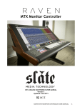
SC-2A
Stereo Corrector
Videoquip Research Limited
595 Middlefield Road, Unit #4
Scarborough, Ontario, Canada. MIV 3S2
(416) 293-1042
1-888-293-1071
www.videoquip.com
1
Phase 3 SC-2A User Manual
The Phase 3 Stereo Corrector allows the user to modify the input phase and
output switching configuration of an incoming stereo audio signal. Figure 1 shows
the front panel switch arrangement, as well as the alternate functions for each
pushbutton in setup mode.
The rear panel provides two XLR-3F connectors for the stereo input signal, and
two XLR-3M connectors for the output signal. The output signal level amplitude
may be trimmed with an adjustment potentiometer for LEFT and RIGHT output.
There are two modes of operation available manual and auto. In MANUAL mode,
the user may choose to invert the phase of the RIGHT channel input using the
PHASE pushbutton. An LED associated with each pushbutton will indicate the
status of each function. When the phase of the right channel is not inverted, the
LED on the PHASE key will be off, and when the phase has been inverted, the
LED will be on. In addition, the output modes available are Left/Right swap which
is designated with the L ÅÆ R symbol, Left Only, Right Only, and Mono sum.
The SC-2A also provides an automatic mode of operation, whereby it will
examine the phase and amplitude of an incoming stereo audio signal, and will
make corrections to phase and output status as it deems required.
The SC-2A will default to AUTO at power-up to ensure that it returns to that
mode of operation during a power failure, after the power is restored. This is
indicated by the green LED associated with the MAN/AUTO switch being on.
Pressing the MAN/AUTO key will place the SC-2A in manual mode, as indicated
by the red LED being on. The user may toggle back and forth between manual
and auto mode simply by pressing the MAN/AUTO key to select the desired
mode.
In the event that a correction is required, an alarm buzzer located inside the
device will sound to alert the user that a correction has taken place.
2
When the SC-2A corrects a phase reversal, the alarm will sound briefly to alert
the user, but the alarm will cease since the phase has been inverted. The SC-2A
monitors the level of the incoming stereo signal and compares it to a preset level
selected by the user during setup. If either the left or right channel of the
incoming signal falls below the threshold for a preset time (silence interval) then
the output will switch to the remaining signal that is above the silence threshold.
For example, if the left channel falls below the silence threshold and remains
there at the end of the selected silence delay, the right channel will be switched
to both outputs. In addition, the RIGHT only LED will be on, and an alarm will
sound. This implies that the right channel will be routed to both outputs for the
duration of the left channel silence. If the missing left channel returns to a level
above the silence threshold, the alarm will cease, and the routing will return to its
previous state. The alarm buzzer may be muted by pressing the CANCEL
pushbutton if it is currently on and the correction is still active. The selection of
the silence level and delay timeout will be discussed later in the section entitled
Calibration and Setup.
Method of Operation
This section will outline briefly the method by which the SC-2A detects and
corrects phase and signal level problems to allow the user to better understand
the limitations of the phase correction signal processing hardware and software.
The basic theory behind the phase detection engine as implemented in software
is that the Left Plus Right (LPR) signal should be greater than the Left Minus
Right (LMR) signal when the phase is not inverted. The left and right signals are
both added and subtracted in analog hardware, and followed by an appropriate
peak signal detector for each. The peak detector provides appropriate attack and
decay times, and gain structure to allow each one to be converted to a digital
signal by an A/D converter inside the microprocessor. The reliability of the phase
detection engine depends primarily on the type of program material. By
observation, it also depends largely on how a particular music track was mixed.
Popular music is mixed primarily with strong center channel information such as
vocals, bass guitar, main guitar, and kick drum. Other instruments including
background vocals and other instrument fills are frequently panned either left or
right to provide a sense of stereo image. Main vocals are frequently mixed with
reverberation tails cross-panned to left / right to provide a sense of depth as well.
Compression helps to provide a “punchy” signal suitable for radio airplay.
Classical or symphonic music however, is best recorded with a stereo MS pair
high above the musicians, with little or no compression to preserve the dynamic
range to provide a sense of realism to capture a true “live” sound. Consequently,
there is not a great deal of center channel information of sufficient amplitude to
allow a significant difference between LPR and LMR.
3
The SC-2A looks for a window between the LPR and LMR of sufficient difference
to allow an accurate determination of phase between left and right channels.
The detection window size is adjustable in real-time via the delay potentiometer
on the front panel of the SC-2A. Figure 2 below shows the effect of this
adjustment.
Figure 2 and Figure 2a above, show a graphic representation of the type of output from the LPR and LMR . A correct
window size for popular music as shown in Figure 2a, will be inadequate for classical or symphonic music since the
difference between LPR and LMR is too narrow to cause the window to trigger properly. Setting the threshold too low may
result in false triggering of the phase detection mechanism, since the LPR and LMR are independent and will frequently
rise and fall at slightly different rates and amplitudes.
Figure 2 and 2a above, depict a situation where the window setting is a good
choice for popular music, but is set too high for classical music. This graphic
representation helps to visualize the operation of the phase detection software.
Figure 2 shows a window size set essentially too wide to properly detect classical
or symphonic music. In general, great care must be exercised in setting the
window size. The SC-2A will provide reliable operation when the window size is
adjusted properly for popular music, and will require a narrower window for
classical music. In general, the so-called “signature” for popular music in Fig 2a
reflects the fact that popular music contains a significant amount of center
channel energy. This energy is more or less in phase, which results in lower LMR
energy, since it cancels when subtracted, but adds to the LPR energy level. If the
LPR energy level exceeds the window setting and is out of phase, the SC-2A will
always accurately detect and correct incoming phase reversals, as soon as they
are encountered.
With classical music, the lack of strong center channel information that is inphase and can cancel to push the LMR energy down to allow a wider detection
window is the main limitation with this method of detecting phase. Note that the
SC-2A software is looking for the relationship between LPR and LMR, and is not
level dependent.
4
Calibration and Setup
The calibration and setup of the SC-2A falls into two categories, default and
operational.
Power-up Defaults Setup
Setting the power-up defaults is a procedure that is done with a special setup
state. To enter the setup mode, hold down the MAN/AUTO switch while turning
on the power switch, and then release the MAN/AUTO switch.
The red and green LED’s associated with this switch will flash alternately back
and forth to alert the user to the fact that the SC-2A is in setup mode, since in
normal operation this action will not occur. The normal pushbutton key functions
are modified in this state to allow the user to set the parameters of operation with
the same keyboard. Figure 3 shows the alternate key functions during setup
mode.
Two parameters may be selected during this setup mode.
1) Silence Detection Level – Uses the L Å Æ R, LEFT, RIGHT and MONO
switches to set the silence level. Signals below these levels in either left or
right channel are interpreted as being silent after the silence timeout interval
has expired. Refer to Figure 3 to select one of four silence level selections.
5
2) Silence Timeout Delay – Uses the MAN/AUTO and CANCEL pushbuttons
to allow the user to set the silence timeout with a wristwatch or stopwatch.
The front panel delay potentiometer allows the user to set a silence delay
timeout from approximately 2 seconds to 60 seconds before the silence alarm
triggers and the appropriate LEFT or RIGHT only audio function is enabled.
When the audio signal in the missing channel returns to a level above the
threshold, the alarm is automatically cleared and the output setting returned
back to its previous state.
Note that if L Å Æ R swap was engaged, that state will be preserved during
this operation.
Setting the Timeout Delay
The timeout delay uses the front panel DELAY potentiometer to set the delay,
and the resulting delay from the position as it is rotated is used to adjust the
overall time delay. If the pot is in the CCW position fully, the delay will be
minimum, and the delay will be maximum at full CW rotation. In order to estimate
the actual value, the flashing LED’s on the MAN/AUTO switch are used to
provide visual feedback.
As the potentiometer is rotated to a different position, press the CANCEL
pushbutton on the front panel. The LED’s associated with the MAN/AUTO switch
will stop flashing, and the green LED will be fully ON during the duration of the
timeout. When the timeout has expired, the LED’s will return to the flashing mode
of operation waiting for a new trigger from the CANCEL pushbutton.
If the desired time delay has been exceeded with the rotation of the
potentiometer, it is not necessary to wait for the end of the timeout to set a new
value. Pressing the MAN/AUTO pushbutton will abort any timeout in progress
and wait for a new trigger. If for example the user wished to set the timeout to 30
seconds and the green LED was still on past the 30 second mark on the
stopwatch, simply press the MAN/AUTO button to cancel that timeout. Adjust the
pot to a lower setting, and trigger the timeout again with the CANCEL
pushbutton. When the desired timeout has been selected, press the PHASE key
to save the selected timeout value, and the desired silence detect level to the
EEPROM memory on the main board.
Each time the SC-2A is powered on, the saved values will be restored from
EEPROM. Since the front panel DELAY potentiometer is not involved in setting
the time delay on an on-going basis, it will free the potentiometer for the real time
selection of the phase detection window.
6
To return the SC-2A to normal operation, simply turn off the power switch, wait
approximately 5 seconds to allow the power supply to return to zero internally,
and then turn on the power again. The unit will power-up ready for operation in
the AUTO mode of operation.
NOTE: It is recommended that the silence timeout delay be set to approximately
1 to 3 seconds initially, since the window size adjustment for phase will require a
short delay to see the effect of changing the window size.
THE SILENCE TIMEOUT DELAY ADJUSTMENT SHOULD BE DONE AFTER
ADJUSTING THE WINDOW SIZE, SINCE THE POTENTIOMETER IS ALSO
USED FOR THE WINDOW SIZE ADJUSTMENT IN REAL TIME.
Operational Setup
The operational setup involves simply trimming the output levels with the OUT R
and OUT L trim potentiometers located on the front panel of the SC-2A. They
provide approximately 3 dB of trim adjustment. Select MAN mode (red LED on)
for this adjustment to prevent the phase and silence detection to operate.
It is important to try to trim the output levels while connected to the upstream
equipment if it is possible. The detection circuitry is taken after the trim
adjustment and any mismatch in the levels will affect the quality of the LMR null.
WINDOW SIZE ADJUSTMENT
1) After the level trim setup is done, connect a source of audio to the SC-2A with
cables of known good phase (no inversion). The nominal operating level of the
SC-2A is + 4 dBu.
2) Turn the DELAY potentiometer fully clockwise (CW to the right) with the
desired music track connected to the SC-2A. To disable the auto phase
correction completely, simply keep the DELAY potentiometer fully clockwise to
make an arbitrarily wide window that cannot trigger a phase correction.
3) Press the PHASE pushbutton. The LED for that button should be on. We will
be using the phase reverse function to allow the phase detection software to flip
it to good phase when the window is at the correct level for the source type.
4) Select AUTO operation.
Note that all pushbuttons are disabled in AUTO operation.
5) Rotate the potentiometer very slowly CCW until the LED associated with the
PHASE pushbutton turns off. Because we artificially introduced a phase inversion
by manually changing the phase in step 3, the SC-2A is correcting the phase in
auto mode back to where it believes it should be.
7
6) Visually make a note of the position of the potentiometer. There is currently no
provision to store the window size in EEPROM memory. The phase detection
software will always use the current position of the potentiometer as the window
size when the SC-2A is operating in AUTO mode. When the Silence Delay
Timeout adjustment is performed, the potentiometer will have to be returned to
the current position for window size.
7) Set the Silence Timeout Delay as described in step 2 on page 6.
8) Re-set the potentiometer to the desired window size as determined previously
on page 7.
The SC-2A should be functional in AUTO mode at this time. To test the unit after
this, it may be desirable to fabricate a special cable that will provide a switch that
will allow phase inversions to be introduced by the user at will, thereby making
further adjustments much easier. A suggested schematic is shown in Figure 4
below.
S1
J1
XLRF-3PIN
2
2
3
3
1
1
SW DPDT
Fig 4 - Suggested schematic for a phase inversion cable
between one output and one input of the SC-2A for introducing simulated
phase inversions. The switch should be a latching type pushbutton switch.
Shown in the normal phase (switch out) condition.
8
J2
XLRM-3PIN
SC-2A Specifications
Power Requirements
115 VAC, 60 Hz or 230 VAC, 50Hz, 6W
Analog Audio Inputs
Input Impedance
Maximum Input Level
Input Connectors
Common Mode Rejection
40 Kohms balanced, 20 Kohms unbalanced
+21 dBu
XLR-3F, x 2
-70 dB @ 60Hz
Analog Audio Outputs
Output Impedance
Output Signal Level
Output Connectors
100 Ohms balanced
+4 dBu nominal
XLR-3M, x 2
Frequency Response
THD + Noise
Hum and Noise
20 Hz to 20 KHz +/- 0.25 dB
0.03% or less @ 0 dBu
-70 dBu, with 22 KHz LPF in measured path
Adjustments
Output Level
Silence Timeout Delay
+/- 3 dB trim range
Approximately 2 -> 60 seconds, front panel
DELAY potentiometer, saved in EEPROM.
Phase Detection Window Size
Variable via front panel DELAY potentiometer
Providing real-time adjustment of window size.
9
Warranty
Videoquip Research Limited (VRL) warrants the SC-2A for a period of 2 (two)
years from the date of shipment from the factory, to be free of defects in
workmanship and material under normal use and service. This warranty is void if
failure is due to abnormal use or modification, or if serial numbers have been
tampered with. VRL’s liability is limited to the repair or replacement of this unit, or
to a sales credit, and the warranty action taken is at the sole discretion of VRL.
Any warranty claims must be received in writing by VRL before the expiration of
the two year period. Warranty coverage does not include shipping costs. This
warranty is in lieu of all other warranties, expressed or implied, and all other
obligations or liabilities of Videoquip Research Limited.
10