1
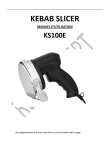
ITALIANO
ENGLISH
KS100E / KS200E
Automation kit
for sliding gate
USER MANUAL
For PCB circuits 425ama-2.00
Made in Italy
EMC 89/336 CEE
KS100E / KS200E - User Manual
Important Safeguards
!
!
!
!
!
!
!
!
!
!
!
!
!
!
!
Please read this manual carefully before the installation and keep it for future reference.
Installation, electrical connections and adjustements must comply with technical and safety standards
in force. (UNI 8612).
HILTRON Srl cannot be held responsible for failure to observe technical standards in the construction of gates, or for
any deformation of gates which may occur during the use.
This product has been designed and manufactured only for the use stated in this manual. Any other use not expressly
set forth will affect the reliability of the product and/or could be source of hazard.
HILTRON Srl cannot be held responsible for any damage caused by improper use or different from the use for wich the
autamtion system is destined to.
Do not use this device in areas subject to explosion: the presence of flammable gas or fumes is a serious hazard.
Before carrying out any operations, turn off the system’s main switch.
An omnipower switch shall be provided for the installation with an opening distance of the contacts of 3 mm or more.
Alternatively, use a 6A thermomagnetic breaker with a multi-pole switching.
Ensure that there is a differential switch up-line of the electrical system, with a trip threshold of 0.03A.
Check that the earthing plant is in perfect condition and connect it to the metallic parts. Also earth the Yellow/Green
wire of the operator.
The end-user must avoid any attempt to repair or adjust the automation personally. These operations must be carried
out only by qualified personnel.
For maintenance operations, use only CIA original spare parts produced by HILTRON Srl. Do not carry out any
modifikeptcations to automation components. Packaging materials (plastic, cardboard, etc.) are a potential hazard
and must be out of reach of children.
The installer must supply all informations regarding manual operation of the system in the event of an emergency and
provide the end-user with this manual attached to the product.
The automation is fitted with an anti-crush safety system that is a torque control device.
In any case, HILTRON Srl suggests the
installation of others safety devices, in
®
accordance with standards in force, system
operating logic and weight and dimension of
the gate.
The safety devices (i.e.: photocells,
DICHIARAZIONE
DI CONFORMITA’
pneumatic edges, etc...) protect areas
SECONDO LE NORME ISO/IEC GUIDA 22 EN 45014
wherethere is a mechanical movement
hazard (i.e.: crushing, entrapment and
COSTRUTTORE: HiLTRON S.r.l.
cutting). Each installation must be fitted with
INDIRIZZO: Via Caserta al Bravo, 218 Napoli
at least one flashing light (i.e.: item
MARCHIO UTILIZZATO:
LAMP12FG) or with at signalling plate (i.e.:
item TRG CIA) fixed to the gate.
CODICE PRODOTTO: PCM100
HILTRON Srl cannot be held responsible
DESCRIZIONE DEL PRODOTTO: CENTRALE DI AUTOMAZIONE PER CANCELLO
regarding safety and correct operation of the
SCORREVOLE
automation in the event that parts other than
Il prodotto sopra descritto risulta conforme ai requisiti prescritti nelle seguenti norme:
CIA
o r i g i n a l p a r ts ( p r o d u c e d b y
HILTRON Srl).
PROGETTAZIONI E PRODUZIONI ELETTRONICHE
!
!
NORMA APPLICATA
TITOLO
EN50081-1 (1992)
NORMA GENERICA DI EMISSIONE
Classe della norma generica: domestico,
commerciale ed industriale leggero.
EN50082-1 (1992)
NORMA GENERICA DI IMMUNITA’
Classe della norma generica: domestico,
commerciale ed industriale leggero.
EN60335-1 (1996)
NORMA PER LA SICUREZZA DEGLI
APPARECCHI ELETTRICI D'USO
DOMESTICO E SIMILARE
La conformita' e' stata valutata sulla base di prove eseguite su campione e con allestimento che
rispecchia la configurazione funzionale prevista per la sua utilizzazione allestita interamente con
prodotti CIA di produzione HiLTRON S.r.l. .
Pertanto il prodotto soddisfa i requisiti della direttiva EMC 89/336/CEE e BT 73/23/CEE.
Napoli, 17 Marzo 1999
L’ AMMINISTRATORE DELEGATO
2
Index
Index
Chapter 1
Introduction
4
1.1 Example of installation ......................................................................................4
Chapter 2
2.1
2.2
2.3
2.4
2.5
2.6
2.7
2.8
2.9
Chapter 3
Geared-motor installation
5
Techincal features .............................................................................................5
Prearrangment of the gate ................................................................................6
Anchorage plate ................................................................................................6
Assembly...........................................................................................................7
Assembly of rack (solution A)............................................................................8
Assembly of rack (solution B)............................................................................9
Installation of magnetic limit-stop FCMM ........................................................10
Emercency operation ......................................................................................12
Mechanical clutch adjustment (MS200 only)...................................................12
Central unit installation
13
3.1 Techincal features ...........................................................................................13
3.2 Board description ............................................................................................14
3.3 Connections ....................................................................................................15
3.3.1 Power supply, flasher, geared-motor, controls .....................................16
3.3.2 Relay photocells connection ................................................................17
3.3.3 Photocells with autodiagnosis connection ...........................................17
Chapter 4
Setup
18
4.1 Operating mode ..............................................................................................18
4.1.1 AUTOMATIC FOR PARK operating .....................................................19
4.1.2 AUTOMATIC operating ........................................................................19
4.1.3 STEP-BY-STEP WITH AUTOMATIC RECLOSING operating .............20
4.1.4 MANUAL STEP-BY-STEP WITH STOP operating...............................20
4.2 Electronic clutch adjustment (trimmer A).........................................................21
4.3 Time of pause adjustment (trimmer B) ............................................................21
4.4 Electronic brake / Slowing down (trimmer C) ..................................................21
4.5 Control LEDs...................................................................................................21
4.6 Remote-control receiver setup ........................................................................22
4.7 Remote-control setup......................................................................................23
Chapter 5
Maintenance
24
5.1 Gate .............................................................................................................24
5.2 Fuses .............................................................................................................24
3
KS100E / KS200E - User Manual
1
Introduction
1.1
Kit content and example of installation
7
3
2
5
6
9
8
4
1
10
12
14
11
13
1
MS100 + PCM100 + FCMS
1
MS200 + FCMS
2
PCM100
FX30 / FX40 / FX55 (TX)
FX30 / FX40 / FX55 (RX)
FX30 / FX40 / FX55 (TX)
FX30 / FX40 / FX55 (RX)
LAMP230G
PULSAR230G
BIRD
SC1
FCMM
FCMM
CRP
TWIN
TRG/EN
3
4
5
6
7
7
8
9
10
11
12
13
14
(KS100E) Geared-motor MS100 with PCM100
central unit and magnetic limit stop sensor FCMS
(KS200E) Geared-motor MS200 and magnetic limit
stop sensor FCMS
(KS200E) PCM100 central unit
Transmitting photocell 1
Receiving photocell 1
(not in KS100PSE) Transmitting photocell 2
(not in KS100PSE) Receiving photocell 2
(KS100E) 230Vac electronic flasher
(KS100PSE) 230Vac stroboscopic flasher
VHF receiver with antenna
Key selector
Magnetic opening limit stop
Magnetic closing limit stop
Plastic rack (optional)
VHF twin channel radio-control
"AUTOMATIC GATE" signalling plate
NOTA: Nel caso del kit KS100 è possibile installare la centrale direttamente all'interno
del motore MS100. Per il kit KS200 è necessario invece fissare la centrale a muro.
4
Geared-motor installation
2
Geared-motor installation
2.1
Technical features
!
!
!
!
!
!
!
!
!
!
!
Mechanical unblocking with key during power supply absence.
Mechanics clutch regolable by setscrew wrench (not included) (only MS200)
Power supply voltage:
230Vca ±10% 50Hz
Normal current absorption:
160W (MS100); 320W (MS200)
Geared-motor speed:
42rpm
Max torque (daN):
500
Operating temperature:
-20°C +55°C
Gate max weight:
1000Kg (MS100);1200Kg (MS200)
Grado di protezione:
IP44
Geared-motorsdimensions(WxHxD):
250x250x150mm(MS100)
195x240x155mm(MS200)
Geared-motors weight:
11Kg(MS100); 18Kg(MS200)
250mm(KS100)
240mm(KS200)
3
1
2
250mm (KS100)
195mm (KS200)
150mm (KS100)
155mm (KS200)
200mm
1
2
3
4
5
6
7
Un-locking key
Anchorage plate
Gate
FCMM (magnetic limit-stop)
Rack
Gate sliding weels
Gate sliding lower guide
5
KS100E / KS200E - User Manual
2.2
!
!
!
!
2.3
Prearrangement of the gate
The gate must have a strong and as far possible indeformable structure.
The lower guide, that can be made with 50x50x5mm. Angolar or other suitable structurals,
must bew perfectly recltilinear and horizontal.
The lower sliding wheels, that will preferably have a diametre of 160mm or 200mm
according to the gate’s weight and dimensions, must have lubricable or tin ball bearings.
The upper guide, that can be made following either the solution A or B must be located so
that gate is perfectly vertical.
Anchorage plate
Introduce the bolts M8x100 the U profile pieces with leg functions, by fastening through the
relevant screw nut. Munt the screws with the legs on the fastening plate; the projection of 25mm must
be kept as reported in the fig.3a
Anchor to the bottm plate by keeping the size of 58.5mm reported inthe fig.3a
!
!
!
!
Notes:
It is suggested to set the plate at least 2cm above ground level.
Arrange plate so that cable through-hole’s position is as shown in the fig.3b
Provide fot a plastic flexible sheath with a diametre of at least 20mm to be introduced into the
plate itself is perfectly horizontal.
Act so that the achoring concrete casting of the plate results compact with the ancorage concrete
casting of the plate results compact withthe anchorage one of the lower guide
2,5mm
Cable through-hole
Gate wing
58,5mm
Anchor plate
Fig.3b
View from top
6
Geared-motor installation
2.4
!
!
!
!
!
Assembly
Remove the 4 screw nuts of the fastening bolts.
Fix the gate actuator to the anchor by means of 4 screw nuts without blocking them. Pay attention
to set the adjustment covers P between the gate actuator and the plate.
Slide below the various rack elements positioning them in contact with the gear (Fig. 11b).
Withdraw four adjustament covers in order to obtain a good black-lash between rack and gear.
Weld once for all the rack support pegs and fix the screw nuts, after having controlled, sliding
manually the gate, that the blocklash gear-rack is always the same.
Remarks: In order to slide manually the gate is necessary to realease by means of the key the
pinion support shaft (refert to instructins Emergency Operation).
Important: After assembling screw the plug of oil (Fig. 13) remove the gasket and screw it on (do
not tighten).
7
KS100E / KS200E - User Manual
2.5
!
!
Assembly of rack (solution A)
Fix the support pegs to each rack element in correspondence of the three slotted holes
by means of the relative blocking screws. Pay attention that the position of the support
pegs is below the hole (fig. 4a and 4b)
Anchor by means of electrowelding the rack support pegs to the gate’s structure
following the distance between the head of the rack the teeth and the anchor plate (see
fig. 5a and 5b).
Remarks: in order to facilitate the correct alignment of the folowing rack elements, it is
suggested to set a third a rack element against two following elements, as shown in
fig.6.
!
8
Control that the various rack elements are perfectly, aligned.Control that the
alignament right line is parallel to the rail in order to do this slide manually the gate and
make sure that the distance between the various rack elements and a fix landmark is
always the same. If not set suitable shims between pegs and rack.
Geared-motor installation
2.6
Assembly of rack (solution B)
It’s possible, if you have o a gear motor of your disposal, to perform as follows
!
!
!
To fix the gear motor to the anchor plate, position it so that the distance between
sprocket and gate is approximately 18mm. (Fig. 7)
Fix to each rack element the support pegs in correspondence of the slotted holes
paying attention to position them in the mid-area of the slot (Fig. 8).
Lean rack element to the sprocket of the gear motor R positioning it as shown in fig.9a.
Then weld then central to the gate’s structure, adeguately strenghtened. Slide
manually the gate until the pag.x is in correspondence of the gear (Fig. 9b) and then
weld the pag.x. Perform the same operation with the pag.x, after having moved it in
correspondence of the wheel R.
9
KS100E / KS200E - User Manual
2.7
!
Installation of magnetic limit-stop FCMM
Fix the two magnets 1 and 2 on the included brackets by the screw; by unscrewing this
screw it will be possible to move the magnet for a final adjustment of the limit-stop. The
magnets are polarized in different way and distinguished by the numbers 1 and 2 as in the
picture:
1
!
2
Lock the already assembled brackets (bracket+magnet) on the rack by the provided
screws.
Magnet 1
10
Magnet 2
Geared-motor installation
!
Mounting the provided plastic blocks as shown in picture “A” it will be available an internal
space of 12mm for mounting on a steel rack.
!
For mounting on a plastic rack of 15mm, mount the plastic block inverted as shown in
picture “B”.
B
A
á
!
12mm
á
15mm
The FCMS sensor inside of the motor has 3 wires, where the BLUE is common, while
the two others (WHITE and BLACK), operates as opening/closing relatively to the
magnets 1 and 2.
11
KS100E / KS200E - User Manual
2.8
Emergency operation
In case of troubles or lack of current, release gate actuator using the appropiate key
and acting on the ENGAGEMENT/RELEASE device as follows:
Open the line switch.
Lift the cover and let it rotate, so as to reach the key-hole.
Introduce release key C.
Turn apposite clockwise, several times until the gate is released.
When emergency situation has ceased, to restore operating conditions, turn the key a
few times, counterclockwise, until it stops turning. Slide manually the gate so that the
teeth of the frontal clutch, if they are in the particolar postion: head against head, can
return to the right position of clutch. Then strongly close the key clockwise again.
Close the line switch.
!
!
!
!
!
MS100
2.9
MS200
Mechanical clutch adjustment (MS200 only)
It's possible to steady the clutch by means of a hexagonal key.
+
12
HEXAGONAL
KEY
Central unit installation
3
Central unit installation
PCM100 Central Unit for sliding gates operates a geared-motor 230Vac 700VA max, as
MS100 or MS200 producted by CIA, by an electrical clutch, realized with a microprocessor of
last generation. PCM100 Central Unit is furnished with a sophisticated circuit of autodiagnosis that controls costantly the operation of the system and connected devices; in case of
troubles, the circuit stops all central unit operation. The monitoring of peripheral operating
connected to the central unit is displayed by LEDs placed on the circuit. Moreover, PCM100
Central Unit is furnished also with a electrical brake to guard the stop of geared-motor. In place
of the brake, the slowing down function is activated 3 seconds before the limit stop to avoid
unnecessary impacts during the opening and closing operating.
PCM100Central Unit is in accordance with EMC 89/336 directives and 73/23 EEC
directives.
3.1
!
!
!
!
!
!
!
!
!
!
!
!
!
!
!
!
!
!
!
!
!
Technical Features
SLOWING DOWN function withBRAKE trimmer at minimum.
BRAKE function adjustable by trimmer with exclusion at minimum.
Programmable operating modes: Automatic, Semiautomatic, step-by-step with automatic reclosing,
step-by-step with STOP.
Built-in interface for BIRD receiver.
TORQUE adjustment by trimmer.
Operation Autodiagnosis.
Peripheral monitoring by LEDs.
Regulation trimmer: BREAK, PAUSE, CROWD FORCE.
Total Opening control input.
Partial Opening control input.
STOP control input.
2 configurable inputs for photocells as IR-SYSTEM with AUTODIAGNOSIS type.
External Box in ABS - IP44.
Power supply voltage: 230V~ ±10% 50Hz
Normal Current Absorption: 6W
FCMS
Service output voltage: 24V~ ±5% max 0,1A
Limit-stop
Opening/closing time: max 90 sec.
sensor
Time of Pause: 4 ÷ 60 sec.
Operating Temperatures: -25ºC ÷ 55ºC
External box dimensions (WxHxD): 127x138x57mm
Board dimensions (WxH): 98x118mm
PCM100 central unit installed
inside of MS100 motor
13
KS100E / KS200E - User Manual
3.2
Board Description
3
2
4
14
15
8
7
6
5
12
11
10
1
21
16
9
13
18
17
19
20
1
Voltage fuse (250Vac 3,15A)
12
LED closing limit stop status
2
Trimmer A: electronic clutch
13
LED STOP Status
3
Trimmer B: time of pause
14
LED microprocessor diagnosis
4
Trimmer C: electr. brake / slowing down
15
Setup Dip-Switch
5
P1: total opening
16
6
P2: partial opening
Opening/closing limit stop connector, to use
when central unit is installed inside motor.
17
LED Button P1
230Vac power supply clamps
7
18
LED Button P2
Flasher and motor clamps
8
19
LED photocell 1 status
BIRD and commands clamps
9
20
LED photocell 2 status
Photocells and 24 Vac clamps
10
21
11
LED opening limit stop status
Opening/closing limit stop clamps, to use
when central unit is installed outside motor.
14
autoapprendimento
codice radiocomando
Central unit installation
3.3
Connections
22
21
20
Limit-stop
connector
1
2
3
4
5
6
7
8
9 10 11 12 13 14 15 16 17 18 19
Use this connector only if central unit
board is installed inside of the gearedmotor.
NOTE: If it should be necessary to
invert the limit-stop wires, invert the
9 and 10 magnets at page 6.
1 - L1
2 - Ground
3-N
POWER SUPPLY 230V~ ±10% 50Hz
4 - Pole 1
5 - Pole 2
6 - Closing
7 - Common (blu wire)
8 - Opening
ELECTRONIC FLASHER 230V~
9 - Pole 1 (clamp 1 BIRD)
10 - Pole 2 (clamp 2 BIRD)
BIRD ANTENNA
11 - Common
12 - Pulse STOP (NC)
13 - Pulse A (NO)
14 - Pulse B (NO)
COMMANDS
15 - NC
16 - Common
17 - NC
18 - 24V~ max 100mA
19 - 24V~ max 100mA
PHOTOCELLS
(FX30 - FX40 - FX55)
20 - Opening limit-stop
21 - Limit-stop common
22 - Closing limit-stop
LIMIT-STOP
Use this clamps only if central unit board is installed outside of the geared-motor.
GEARED MOTOR
230V~ 700W max
15
KS100E / KS200E - User Manual
3x1,5mm
BIRD
( 8 page 4)
N
Ground
3x1,5mm
L1
2x1mm
Power supply, flasher, geared-motor, commands
2x1mm
3.3.1
POWER
SUPPLY
230V~ ±10% 50Hz
Partial
opening
2B
Total
opening
Optional Controls
buttons (entry phone, etc.)
WARNING: Use a shielded
cable with two wires, 2S
type, only for the connection
of BIRD receiver.
Do not use free wire of
another devices.
We rember you to look out
the polarity during the
connection.
PULSAR230G
LAMP230G
( 7 page 4)
Flasher
230V~
MS100
( 1 page 4)
230V~ 700W max
STOP
NC
NO
4S
SC1 (
9
OPEN
CLOSE
page 4)
Closing
Common (blu)
Opening
N.O.
16
Timer
To leave the gate opened, it’s possible to connect a timer,
as shown above (par.3.2.1), and to set the opening of the
gate in a given time. (i.e.: 7:00 ÷ 8:30 a.m.)
When the timer is activated (relay contact from NA
Normally Open to NC Normally Close), the opening of the
gate will stop up to the timer contact will be NC Normally
Close.
Installation
2.3.2
DIP1
Relay photocells FX40, FX55
ON
5
3 4
2
(3
page 4)
5
3 4
2
(5 page 4)
1
2
(4 page 4)
1
C NA NC
1
2
(2 page 4)
1
C NA NC
SW4=OFF
2.3.4
DIP1
Photocells with autodiagnosis FX30
ON
1
2
2
1
1
(4 page 4
2
(2 page 4)
1
2
SW4=ON
(3
page 4)
(5 page 4)
NOTE: If you work with photocell type FX30, you must connect both photocell 1 and photocell 2 .
17
KS100E / KS200E - User Manual
4
Setup
4.1
Operating mode
The operating mode and the various options are settable by the switches 1, 2 and 3 of the
dip-switch present on the board ( 15 at page 14). The switch 4 can set the installed photocell
model (see previous page). Here's a summary of all options:
ON
Automatic for Park
operating
OFF OFF
Automatic operating
ON
OFF
Step by step
with automatic closing
OFF
ON
Step by step
with STOP
ON
ON
Locking enabled
ON
Locking disabled
OFF
FX30 (autodiagnosis)
ON
FX40 - FX55
OFF
ON
Switch 1 and 2:
Operating
ON
ON
ON
Switch 3:
Opening locking
on
photocells
interruption
ON
ON
SWITCH 4:
Tipo di
fotocellula
installata
ON
To learn about operating logics see next paragraph.
ATTENTION: The DIP- SWITCH setting up has to be made with central unit switched off.
18
Setup
4.1.1
AUTOMATIC FOR PARKS operating
(SW1=OFF - SW2=OFF)
One pulse allows : opening , pause , automatic closing .
During the opening operation, other pulses will be ignored. During the closing operation,
possible pulses stop and reverse the movement of gate immediately.
A contact closed on PULSE A ( Clock function ) allows to open the gate up to the setted pause
and it be open up to the opening of the contact.
GATE
STATUS
PULSE A
CLOSE
Total Opening and
reclosing after the time
of pause
PULSE B
STOP
Partial Opening and Disables A and B pulses
closing operation after and disable opening
the time of pause
ON
PHOTOCELL 1 PHOTOCELL 2
See SWITCH 3 pages 9 and 10
No effect if the opening
is started by the
PULSE A
OPENING
PARTIAL
OPEN
IN PAUSE
TOTAL
OPEN
IN PAUSE
Total Opening if the
opening is started by
the PULSE B
Total Opening
No Effect
No Effect
The reclosing is stopped
and at the end of the
pause it restores other 5
sec. up to the reset
Stops operation
and switches to
STOP mode
The reclosing is stopped and at the end of the
pause, it restores other 5 sec. up to the reset
A total opening is possible.
The reclosing is stopped and at the end of the
pause, it restores other 5 sec. up to the reset
The reclosing is stopped and at the end of the
pause, it restores other 5 sec. up to the reset
CLOSING
The closing is stopped and the gate opens
again immediately
Stops operation and the gate opens immediately
IN STOP
Restarts the operating procedure before the
STOP (closing or opening)
4.1.2
The pulses A and B will be ignored.
The opening or closing operation are locked
AUTOMATIC operating ( SW1=ON - SW2=OFF)
ON
One pulse allows :opening, pause, automatic closing.
During opening and closing procedures, every pulse stops and reverse the movement of the
gate immediately.
During the pause, a pulse recloses the gate immediately.
GATE
STATUS
PULSE A
CLOSE
Total Opening and
reclosing after the time
of pause
PULSE B
STOP
Partial Opening and
Disables A and B pulses
reclosing after the time
and disable opening
of pause
OPENING
The gate stops and it recloses immediately.
OPEN
IN PAUSE
The gate recloses immediately
CLOSING
The gate stops and it opens immediately.
IN STOP
Restarts the operating procedure before the
STOP (closing or opening)
PHOTOCELL 1 PHOTOCELL 2
See SWITCH 3 pages 9 and 10
No effect
Stops operation
and switches to
STOP mode
The reclosing is stopped and at the end of the
pause, it restores other 5 sec. up to the reset
Stops operation and the gate opens immediately
The pulses A and B will be ignored.
The opening or closing operation are locked
19
KS100E / KS200E - User Manual
4.1.3
STEP-BY-STEP WITH AUTOMATIC RECLOSING (SW1=OFF- SW2=ON)
ON
One pulse allows : opening, pause, automatic closing
During opening and closing procedures, every pulse stops and reverse the movement of the
gate immediately.
During the pause, a pulse recloses the gate immediately.
GATE
STATUS
PULSE A
CLOSE
Total Opening and
reclosing after the time
of pause
PULSE B
Partial Opening and Disables A and B pulses
closing operation after and disable opening
the time of pause
OPENING
The opening is stopped and the next pulse
recloses the gate
OPEN
IN PAUSE
Recloses the gate immediately
CLOSING
It is locked and only a new pulse recloses the
gate
IN STOP
Restarts the operating procedure before the
STOP (closing or opening)
4.1.4
STOP
PHOTOCELL 1 PHOTOCELL 2
See SWITCH 3 pages 9 and 10
No Effect
Stops operation
and switches to
STOP mode
The reclosing is stopped and at the end of the
pause, it restores other 5 sec. up to the reset
Stops operation and the gate opens immediately
The pulses A and B will be ignored.
The opening or closing operation are locked
MANUAL STEP-BY-STEP WITH STOP operating (SW1=ON - SW2=ON)
ON
One pulses opens; the next pulse stops; the next pulse closes ; the next pulse stops; the
next pulse opens, etc .
DIP1
20
GATE
STATUS
PULSE A
PULSE B
STOP
PHOTOCELL 1 PHOTOCELL 2
CLOSE
Total Opening
Partial Opening
Disables A and B pulses
and disable opening
See SWITCH 3 pages 9 and 10
OPENING
The opening is stopped and the next pulse
recloses the gate
STOP
Reverses the movement of the motor
CLOSING
The closing is stopped and the next pulse
opens the gate
IN STOP
Restarts the operating procedure before the
STOP (closing or opening)
No Effect
Stops operation
and switches to
STOP mode
Pulses A and B are ignored and all movement
are locked
Stops operation and the gate opens immediately
The pulses A and B will be ignored.
The opening or closing operation are locked
Setup
4.2
Electronic clutch adjustment (trimmer A)
This adjustment works on the thrust force of geared-motor: this force must cause the
moving of the gate, and it’s closely dependent on the weight of its structure.
During the movement, also the gate acquires a thrust force.
Under provisions of the law, the adjustment must be made so that the thrust force of the
gate is equal to 15Kg; it means that a force equal to 15Kg, in opposition to the movement of the
gate, must stop the gate during its movement.
To set this adjustment, we suggest you to use an instrument called linear dynamometer.
4.3
Time of pause adjustment (trimmer B)
If the central unit is setted on Automatic operating or Automatic operating for Parks, you
must adjust the time of pause that must elapse between the end of the opening and the start of
the closing of the gate.
4.4
Electronic Brake / Slowing Down (trimmer C)
Turned in anticlockwise direction:
Electronic brake:
disabled
Slowing down:
enabled at the end of opening / closing
Turned in clockwise direction:
Electronic brake:
Slowing down:
4.5
enabled, reduces the movement after the limit/stop is
activated.
disabled
Control LEDs
Here's a summary of the signallings LEDs present on the board (see page 14):
LED
COLOR
7
green
8
green
9
ON
Pulse on input A
(total opening)
Pulse on input B
(partial opening)
BLINKING
OFF
/
st/by
/
st/by
red
st/by
/
Photocell 1 engaged
10
red
st/by
/
Photocell 2 engaged
11
red
st/by
/
12
red
st/by
/
Opening limit-stop
engaged
Closing limit-stop
engaged
13
yellow
st/by
/
STOP command active
14
green
Anomaly
Normal operating
Anomaly
21
KS100E / KS200E - User Manual
4.6
Remote-control receiver setup
Visualization of the programmed code
!
!
!
Keep pressed P1 and P2 buttons ( 5 and 6 at page 11) for at least 2 seconds and not more
than 5 seconds, up to the two LEDs ( 7 and 8 at page 11) light on.
Pressing the P1 button it will be displayed the 12-bit code of "A" channel by a sequence of
blinkings of the LEDs:
!
one blink of LED 7 indicates dip switch ON
!
one blink of LED 8 indicates dip switch OFF
At the end of the sequence, it will exit automatically the setup mode.
NOTE: If no buttons is pressed in 5 seconds, the produre is stopped and no code will be
displayed.
NOTE: To visualize the code of the “B” channel, repeat the same procedure using the P2
button.
Auto-learning of the remote-control code
!
!
!
!
Keep pressed P1 and P2 buttons ( 5 and 6 at page 11) for at least 5 seconds up to the two
LEDs start to blink ( 7 and 8 at page 11).
Press P1 button, only LED 7 starts to blink.
During the blinking, within 5 seconds press the "A" button of the remote-control to let
acquire the code.
The LED 7 starts a sequence of blinkings to indicate that the code has been acquired and
it will exit automatically the setup mode.
NOTE: If no remote-control is activated in 10 seconds, the setup is stopped and no code will
be programmed.
NOTE: For the acquisition of the code of the channel "B” of the remote-control, repeat the
procedure using P2 buttons and LED 8 .
Summary of setup accessing times
Time of simultaneous pressure of P1 e P2 buttons:
0 sec.
LED Status
Function
22
2 sec.
5 sec.
LED “1” and “2”
turn off
LED “1” and “2”
light
LED “1” and “2”
blink
No action
Release P1 and P2
buttons to enter in Code
Display Mode.
Release P1 and P2
buttons to enter in
Auto-acquisition Code
Mode
Setup
4.7
Remote-control setup
The TWIN allows the independent set-up for each of 2 channels; It’s possible to memorize
a different code on each button, and a channel to select (A, B, C, or D) also if they are not on the
same code. The set-up operation has to be repeated for each of the 2 buttons of the radiocontrol.
In order to start the set-up phase you have to push both the buttons for some seconds,
until the LED remains on, then you have to leave them:
+
For insert a new code you have to access with the following sequence: "1" - "1" - "0" - "0”
!
Insert the 10 digit of the code using:
?
?
!
During the insert of each code the LED will switch off for some seconds.
Insert the 2 digit of the channel using:
!
!
? Channel A "1" - "0": It means the left button for the previous TWIN versions
? Channel B "1" - "1": It means the right button for the previous TWIN versions
? Channel C "0" - "0": to use together with quadri-channels receivers
? Channel D "0" - "1": to use together with quadri-channels receivers
Push the button that you want to assign at the code.
The LED switch off at the end of the set-up.
&
*
“0” (right button ): It means dip-switch "OFF" for the previous TWIN versions*
“1” (left button): It means dip-switch "ON" for the previous TWIN versions*
For example, to duplicate the left button (channel A) of a previous TWIN version that has the dip-switch set as
following:
ON
OFF
1
2
3
4
5
6
0
0
1
7
8
9
10
You have to digit the following buttons sequence:
1
+
1 0 0
Access
1
0
0
1
1 0
code
1
1 0 (fast flash of the LED)
1
channel A
assigned to left button
For read the code you have to digit the following sequence:"1" - "0" - "1" -"0"
!
Push on the button that you want to know the code
!
The LED switch off and it start one series of 12 flashes:
?
A brief flash means "0"
?
A long flash means "1”
During the set-up, if you don’t push on any button for at least 5 seconds the LED switch off and the setting phase
finish automatically.
Unscrew the screw on the bottom of the radio-control to open the plastic cover, take off the old battery and insert a
new one according with the polarities indicated on the plastic cover.
Check the correct operation of the two buttons after to close the plastic cover.
23
KS100E / KS200E - User Manual
5
Maintenance
5.1
Gate
It`s suggested to carry out periodic checks on the structure of the gate and in particular it`s
suggested to verify verificare the perfect condition of gears, ruck and all mechanical elements.
!
!
5.2
F1
24
Grease periodically the spocket wheel rackwork kinematic system.
Chek periodically (at least once every 6 months) the sensibility of the clutch. To perform this
operation, act by means of the key on the specific adjustament pawl, so that the operating force,
estimated manually on the gate wing, does not exceed a thrust of 7/8kg.
Fuses
3,15A 250V
VOLTAGE Fuse
This fuse allows the protection from
overloads of the central unit transformer,
from voltage drops of the flasher and of the
geared-motor.
272BDE-1.04