1
INTEGRATED SYSTEMS AND CONTROL, INC.
User Manual
PCM100
INTEGRATED SYSTEMS AND CONTROLS, INC.
PCM100 Users Manual V2.0a
Integrated Systems and Control. Inc.
PO Box 7682, Auburn, CA 95604
Phone 530-878-9038 • Fax 530-878-9137
Revised 3/28/2001
Table of Contents
General
Specifications
Installation
Operation
Service
3
4
9
10
13
2
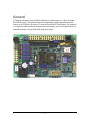
General
To bring the advantages of the PCM400 technology to smaller systems, we have developed
the PCM100 system. The PCM100 shares the programming, logging and communications
features of the PCM400 with a lower I/O count and a built-in low cost Modem. It is comprised
of a single board that contains the microprocessor and memory, the I/O and contains the screw
terminals required to connect all the field wiring to the board.
3
Specifications
Board Size: Height = 4.25”, Width = 6.2”, and Depth = 2.25” (including it’s plastic track
mounting..
Input Power: 36VAC transformer (w/center tap) is used to provide power. The
recommended transformer is the Signal Transformer, DP241-6-36. The input power is fused
(F1) at 0.4 Amps (SloBlo). The IDC connector for termination of power is an AMP #6404264. Connections are made to this connector using manual or powered tools to ensure proper
connections.
Output Power: Terminals are provided on the PCM100 Board for providing 24VDC and
5VDC power for external sensors. This 24vdc output is limited to a maximum current of .25
amperes and the 5VDC output is limited to a maximum of 40ma. The 24VDC power is
unregulated and may vary in voltage from 29VDC to 23VDC, depending on load and line
voltage.
Analog Inputs: The PCM100 board set has terminals for 4 analog inputs which may be used
as either 0-5VDC, 0-20ma, 4-20ma, or 10K Thermistor temperature inputs. A board jumper
may be used to connect the input to a 250 Ohm 1% resistor for 0-20ma or 4-20ma inputs.
These analog inputs have an input impedance of 30K Ohms and a maximum of 5VDC voltage
range. The board’s A/D converter resolves the input voltage to 10 bits or 1 out of 1024. For
an input of 5VDC, each resolved bit represents 4.88 millivolts. When used in the real world,
you can expect an accuracy of, + or -, 2 bits in good conditions. Each analog channel is
sampled and averaged over 4 control scan periods to produce the value used by user programs.
The A/D converter is uni-polar, meaning that it only measures positive voltages, 0-5VDC.
Digital Inputs: The PCM100 board has 8 digital inputs (DI#1 thru DI#8) which are selfpowered from the 24VDC power such that only a contact closure is required to activate them.
Screw terminals on the board are provided for connections.
Digital Outputs: The PCM100 board has 4, normally open relay outputs, designed to switch
a maximum of 1.0 amp at 230VAC. The maximum relay life will be attained when driving
contactors that require 8 Watts or less holding power. Fuse F2 protects the outputs and is
rated at 5A.
Serial Port #1, MODEM : The PCM100 Board is equipped with an on-board 2400 Baud
MODEM. Connection to the phone line are made by J1, a standard RJ11 phone connector.
4
Serial Port #2, RS232: The PCM100 Board contains a serial port that can be used as a
service laptop computer interface port. The board contains a 9 pin (DB9 type connector (J2)
that, with a “Null Modem” cable adapter, can be connected to a laptop computer.
5
Installation
Installation Considerations
The power supply wiring between the PCM100 board and the transformer should be kept as short
as possible. Technically, the boards power supply could float such that the RET ground
conductor need not be connected to the earth ground. The only exception would be if sensors or
other connected equipment external to the board will cause the RET conductor to be grounded, it
would be better to ensure that RET is grounded at a known point near the board. The on-board
heatsink is designed to cool the 5VDC logic supply regulator and it gets hot to the touch!. Care
must be given to ensure that wiring does not lay against this heatsink.
The Analog Inputs may be configured to accept 0-5VDC or 4-20ma type sensors. In addition, a
Precon III, 10K, thermistor may be connected for temperature measurements. A Thermistor
sensor should be connected between 5VDC Thermistor Power and the Analog input terminal
(with the 4-20ma jumper removed). As always, the wiring to analog sensors should be kept away
from other switching and power lines to ensure good analog accuracy.
The Digital Inputs are powered such that a connection made through a field dry contact closure
between the DI terminal and one of the RET terminals will cause the corresponding LED to light
and activate the logical input signal. The inputs are powered by 24VDC and must not be
connected to AC voltages of any value.
The Digital Outputs are relay contact closures with one side of each contact connected to a
common conductor. These outputs are rated for voltages not to exceed 230VAC and intended to
operate 8 Watt or smaller loads for the maximum relay contact life. Each relay output is a
Normally Open contact (a Normally Closed type contact is not available). The common
conductor is fused.
PCM100 Summary of Connections
The following tables define the function of each of the PCM100’s connections:
Connectors:___________________________________
TB1 (Input Terminations)
1 - AI#1
2 - AI#2
3 - AI#3
4 - AI#4
5 - IRET
6 - IRET
7 - 5VDC sensor power supply (40ma max).
6
8 - 24VDC power (0.25A max).
9 - DI#1
10 - DI#2
11 - DI#3
12 - DI#4
13 - DI#5
14 - DI#6
15 - DI#7
16 - DI#8
17 - RET
18 - RET
TB2 (Output Terminations)
1 - DO#1 (NO relay contact, common side to TB2-5).
2 - DO#2 (NO relay contact, common side to TB2-5).
3 - DO#3 (NO relay contact, common side to TB2-5).
4 - DO#4 (NO relay contact, common side to TB2-5).
5 - Common
J1 (MODEM, RJ11 Telephone Connector)
1 - n/u
2 - n/u
3 - TIP
4 - RING
5 - n/u
6 - n/u
J2 (Serial Port #2, RS232)
1 - n/u
2 - RX DATA (input)
3 - TX DATA (output)
4 - DTR (output)
5 - COM
7 - RTS (output)
8 - CTS (input)
9 - n/u
J3 (Power Input Connector)
1 - 18VAC (one leg of 36VAC transformer secondary).
2 - 18VAC (one leg of 36VAC transformer secondary).
3 - AC/DC RET (center tap of 36VAC transformer secondary).
4 - Optional Battery backup input (12VDC to 24VDC, approx. 0.15A).
7
J4 (future use)
J5 (future use)
Jumpers used to configure the PCM100 Board for hardware related features:
JU1 - AI#1 input range, Removed = 5vdc or Thermistor, Installed = 4-20ma.
JU2 - AI#2 input range, Removed = 5vdc or Thermistor, Installed = 4-20ma.
JU3 - AI#3 input range, Removed = 5vdc or Thermistor, Installed = 4-20ma.
JU4 - AI#4 input range, Removed = 5vdc or Thermistor, Installed = 4-20ma.
JU5 - Install to enable the battery support for the memory. Remove for shipment.
JU6 - If installed, the PCM100 will always answer the phone. Normally removed.
8
Installation Topics
Scaling Analog Inputs
When scaling a sensor, the minimum/maximum scaling values must be calculated. The minimum
and maximum scaling values entered into the Analog Input Definition represents the values that
are represented when 0 volts and 5 volts, respectively, are measured at the analog input
terminal. The simplest method to calculate the proper scaling values for typical sensors are
shown below in several examples.
Example 1:
A 4-20ma liquid level sensor is to be scaled. The sensor operates over a range of 0 to 15 feet
of liquid, where 4ma=0 feet and 20ma=15 feet. The simplest way to scale a 4-20ma sensor is
to take the range of the sensor, divide it by 4, then subtract the result from the 4ma sensor
value.
V4 = level value at 4ma sensor output
V20 = level value at 20 ma sensor output
Minimum Scale Value = V4 - (V20 - V4)/4 = 0 - (15 - 0)/4 = 3.75 feet
Maximum Scale Value = V20 = 15.0 feet
Example 2:
A 0-5VDC voltage type liquid level sensor is to be scaled. The sensor operates over a range of
0 to 15 feet, where 0.7 volts=0 feet and 4.2 volts=15 feet. Note that voltage sensors are not
neatly calibrated at the factory for standard voltage values. The calculations required are as
follows.
M = slope of voltage vs depth in volts per feet (or inches or whatever)
Vdry = voltage output of the sensor when removed from the liquid.
Vx = voltage at some known depth, Dx.
Dx = some known depth at which Vx can be recorded (usually sensor maximum).
Minimum Scale Value = the minimum value to enter into PCM100’s definition.
Maximum Scale Value = the maximum value to enter into PCM100’s definition.
M = (Vx - Vdry)/Dx = (4.2 - 0.7)/15 = 0.23
Maximum Scale Value = (5.0 - Vdry)/M = (5.0 - 0.7)/0.23 = 18.7 feet
Minimum Scale Value = -Vdry/M = -0.7/0.23 = -3.0 feet
9
Operation
PCM100 Operation and Programming
The idea behind the PCM100 design is to combine the programming features of the PCM400
Masters with reduce hardware and more flexible packaging. The following paragraphs describe
the main differences between the PCM100 programming and the PCM400A’s.
Programming considerations of the PCM100
The firmware revision of the PCM100 is currently V1.00. The development of programs must
be done with the appropriate (v1.00x) Simulator software. Programs written for the
PCM400A WILL NOT directly load into an PCM100 board or Simulator program without
significant changes.
The MAILBOX concept is different from that of the PCM400. In the PCM100, the Mailbox
#1 is designed to be used as a “PHONE-HOME” mailbox. This means that this Mailbox will
be used to direct the call out to the host monitoring site on a monthly basis. This scheduling can
be accomplished one of two ways. Using the Simulators Mailbox Definition screen, the
Mailbox can designate either a Point to enable the Mailbox or a “Phone-Home” Date and Time
specification can be directly entered into the Mailbox definition. If the Date/Time, “PhoneHome” specification is used, a particular day of the month (MM/DD/YY format or 1L|DOW|MTH format may be used) can be specified and a particular time of the day specified.
By default, the PCM100 will install the Mailbox #1 specifying that “1|MON|*” (meaning the
First Monday of every Month) as the Date and “1:30” as the Time. The PHONE-HOME
Mailbox is designed to allow a regular access for monitoring purposes. The Host Monitoring
Software will be able to specify certain logs for automatic retrieval at the next PHONE-HOME
event.
Programming an PCM100 board is a two step process. Once the operating program has been
developed using the Simulator software, it must be “LOADED” into the PCM100 board using a
“Load Programming” function of IWATCH, ILISEN or COS. This first step establishes that
this program is now operating in the board. The second step is to SAVE this new operation
program into the PCM100’s backup memory device by performing a “BSV” command in
command mode or by performing a “Save to Backup” function using the full screen mode.
Important: The act of Loading a program into the PCM100 does not automatically update it’s
backup memory device. This is done to allow the testing of a new program without the loss of
the original, which can be restored at any time.
10
The Unit ID String is new to the PCM100. It’s purpose is to describe in a way that the Host
software can recognize easily, the unique identification of a particular PCM100 board panel.
The ID String may be up to 15 characters long. It is suggested that the first few characters
identify a specific customer or a specific development. For instance, if a customer named
“Global Environmental” is monitoring and servicing a number of PCM100 equipped panels, they
should be given an ID such as “GEAT00001” through “GEAT99999”, where the “GE”
identifies the customer/service company, “AT” identifies the panel as PCM100 based. This
unique ID string is sent to the Host, or other, monitoring software during the regular PHONEHOME event, which will quickly identify what panel is reporting.
Operational considerations of the PCM100
A new IWATCH, version 2.54C+, must be used to access the PCM100’s.
A new ILISTEN, version 1.00G+, must be used to access the PCM100’s.
The intended operation of the PCM100 is to initiate a callout periodically to a monitoring site. It
is rarely, if ever, intended to auto-answer the phone line. For testing purposes, the jumper JU6
is used to, when installed, force the PCM100 to always answer the phone line. When the JU6
jumper is removed, the PCM100 will only be able to callout, except that the user may press the
“TEST” button on the board, which will instruct the PCM100 to answer the phone line for the
next 5 minutes. If the TEST button is pressed, it must be held down for at least one scan time
(2 seconds by default). The Serial Port #2 (connected to J2) must be disconnected for the auto
answer options to work properly. The ISAC program “ILISTEN” is intended to receive the
regular calls from the PCM100’s.
For testing purposes, there two special diagnostic functions that can be accessed at power up
time. First, with JU6 removed, and the TEST button pressed during power up, the board
firmware will perform a program clear and clear all the logs. The second function is accessed
by installing JU6, and pressing the TEST button during power up. This is a special board
diagnostics mode. If a terminal or laptop is connected to Serial Port #2, a “TESTMODE>”
prompt will be issued. Currently, the only commands in the Test Mode are the “MEM” and
“RET” commands. The MEM command performs a RAM memory and EPROM memory test.
At the conclusion of the test, the prompt will be printed again. To exit the Test Mode, enter the
command “RET”, which will return to normal PCM100 operation after clearing all the logs. If a
valid program is present in the PCM100 backup memory, the user may reload it using the BRS
command or via the MENU command and selection “R” on the full screen menu.
During normal operation, the “OK”, green colored LED light, will blink at a rate of one second
on, one second off. This blink will stop when performing program loads and unloads.
When the PCM100 is set to answer with it’s Modem or when a user connects directly to the
board with a laptop computer, the PCM100 responds with a “ATRTU PASSWORD>”
prompt. If the user incorrectly types the logon command, the board will respond with
11
“Password ERROR” and repeats the prompt. The correct logon command is
“LOGN,{name},{password}” then press the Enter key. The “name” is a alpha character string
of 15 or less characters. The “password” is a numerical character string of 15 or less
characters. The default factory name and password that is installed when the user performs a
“Clear All Programming” function in the Simulator program, is name=”rtu” and
password=”123”. Other passwords may be added and the default name/password may be
changed by using the Simulator program.
Once the user has logged on to the PCM100, the unit responds with a “Logged On” message
and changes the prompt to “ATRTU>”. From this “ATRTU>” prompt, there are a number of
commands that may be typed into the PCM100. Some of the commands are designed for use
only with the IWATCH, ILISTEN, and COS programs. A list of the available commands are
shown below.
Command Mode Command Summary
"BRS" Command
The BRS command causes the current operating program to be replaced by the program saved
in the backup EEPROM memory device. The syntax is “BRS”(Enter). There is no response if
successful, an error message is printed if a problem is detected.
"BSV" Command
The BRS command causes the current loaded operating program to be saved into the backup
EEPROM memory device. The syntax is “BRV”(Enter). There is no response if successful, an
error message is printed if a problem is detected.
"CAL" Command
The CAL command causes the entire Alarm Log to be cleared. The syntax is “CAL,0”(Enter).
The unit will respond with “Log Cleared”.
"CAT" Command
The CAT command causes the entire Activity Log to be cleared. The syntax is
“CAT,0”(Enter). The unit will respond with “Log Cleared”.
"CML" Command
The CML command causes the entire Maintenance Log to be cleared. The syntax is
“CML,0”(Enter). The unit will respond with “Log Cleared”.
"COM" Command
The COM command is used for monitoring certain values for diagnostic purposes. It is not
used at this date. The syntax is “COM”(Enter).
"COS" Command
12
The COS command is used to clear the Optimizer Logic history table. The syntax is
“COS,x”(Enter), where ‘x’ is the Optimizer number.
"CUL" Command
The CUL command is used to clear one or all of the User Logs. The syntax is “CUL,x”(Enter),
where ‘x’ is ‘0’ to clear all logs, or is 1-16 to clear that particular log#. The unit will respond
with “Log Cleared”.
"DIE" Command
The DIE command is only used when the user wishes to completely reset the unit as though a
power failure has occurred (a power failure will be recorded in the Alarm Log). The syntax is
“DIE”(Enter).
"IDN" Command
The IDN command is used to display the unit ID character string. The syntax is “IDN”(Enter).
"LOGN" Command
The LOGN command is used to log on to the PCM100 board and gain access to the interface.
The syntax is “LOGN,{name},{password}”(Enter), where “name” and “password” are
character strings that have been defined for the particular PCM100 being accessed. If the log
on is accepted, the unit will respond with “Logged On”, else an error message will be printed.
"MENU" Command
The MENU command changes the interface from that of a prompted command/response to a
full screen interactive interface. The syntax is “MENU”(Enter).
"RAL" Command
The RAL command is used only by the IWATCH, ILISTEN and Host software.
"RAT" Command
The RAT command is used only by the IWATCH, ILISTEN and Host software.
"RET" Command
The RET command is used only by the IWATCH, ILISTEN and Host software.
"REV" Command
The REV command returns the current firmware rev and the last date of program modification.
The syntax is “REV”(Enter).
"RML" Command
The RML command is used only by the IWATCH, ILISTEN and Host software.
"RUS" Command
13
The RUS command is used only by the IWATCH, ILISTEN and Host software.
14
15