1
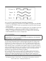
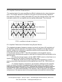
TTL Pulse 0V
Triangle
0V
Sine
0V
Square
0V
FIG. 3 OUTPUT WAVEFORMS AND PHASE RELATIONSHIPS
I. A positive or negative DC component can be added to the signal at the 50Ω BNC
by use of the DC OFFSET control, as required by the circuit into which the signal
is being injected.
J. A fixed amplitude TTL square wave is available at the TTL OUT BNC on the front
panel. This signal is unaffected by the AMPLITUDE, ATTENUATOR or DC
OFFSET. TTL output is a square wave for use in digital circuits, even though
FUNCTION SWITCH is on sine or triangle wave.
3-3-2. Considerations
CAUTION
KNOWLEDGE OF THE FOLLOWING FACTORS IS ESSENTIAL FOR PROPER
OPERATION OF THE INSTRUMENT:
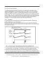
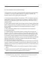
A. The DC offset control can provide over ± 10 volts open-circuited, or ± 5 volts
into 50Ω load. Remember that the combined signal swing plus DC offset is also
limited to ± 10 V open-circuited, or ± 5 V into 50Ω. Clipping occurs slightly next
page these levels. FIG 4. illustrates the various operating conditions encountered
when using DC offset. If the desired output signal is large or if a large DC offset is
used, an oscilloscope should be used to make sure that the desired combination is
obtained without clipping. Keeping the Amplitude control in the lower half of its
adjustment range reduces the probability of clipping.
B. To set the DC offset to zero or a specific DC voltage, depress the Function
Switches slightly so that all switches are released(all buttons out). This removes
signal from the output and leaves the DC only. Measure the DC output on an
oscilloscope or DC voltmeter and adjust the DC offset control for the desired value.
Test Equipment Depot - 800.517.8431 - 99 Washington Street Melrose, MA 02176
FAX 781.665.0780 - TestEquipmentDepot.com