1
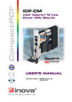
CompactPCI
®
ICP-K6
High-Performance
CPU Boards
USER’S MANUAL
Publication Number: PD00030010.xxx AB
MAN-ICP-K6
This user’s manual describes a product that, due to its nature, cannot describe a particular application. The content of this user’s manual is furnished for informational use only, is subject to change
without notice, and should not be constructed as a commitment by Inova Computers GmbH.
Inova Computers GmbH assumes no responsibility or liability for any errors or inaccuracies that
may appear in this user’s manual.
Except as otherwise agreed, no part of this publication may be reproduced, stored in a retrieval
system, or transmitted, in any form or by any means, electronic, mechanical, recording, or otherwise, without the prior written consent of Inova Computers GmbH.
Products or brand names are trademarks or registered trademarks of their respective companies or
organisations.
Inova Computers GmbH
Sudetenstrasse 5
D-87600 Kaufbeuren
Germany
Inova Computers Inc,
270 Communication Way, Bldg. #6
Hyannis, MA 02601
USA
Tel.: ++49 (0) 8341 62 65
Fax: ++49 (0) 8341 62 69
email: [email protected]
Tel.: ++1-508-771-4415
Fax: ++1-508-771-4346
email: [email protected]
http://www.inova-computers.com
Preface
CompactPCI
®
ICP-K6
Preface
Contents
Unpacking and Special Handling Instructions ............................................... 4
Revision History ............................... 5
Three Year Limited Warranty.............. 6
1.0 ICP-K6 CPU Family .................. 1-2
1.01 Interfacing ...............................................................................................
1.02 Peripherals ...............................................................................................
1.03 Software ..................................................................................................
1.04 Graphics ..................................................................................................
1-3
1-3
1-3
1-3
1.1 Specifications ......................... 1-4
1.2 Configuration .......................... 1-6
Table 1.30 ‘Processor Overview .................................................................................................. 1-6
Figure 1.2 ICP-K6 Overview ....................................................................................................... 1-7
1.3 Fieldbuses .............................. 1-8
1.31 CAN ......................................................................................................... 1-8
1.32 PROFIBUS................................................................................................. 1-8
1.33 INTERBUS-S.............................................................................................. 1-8
1.4 Software ................................ 1-9
1.41 VenturCom ..............................................................................................
1.42 LP Elektronik ............................................................................................
1.43 VxWorks ...................................................................................................
1.44 OS-9 x86 .................................................................................................
1.45 QNX ........................................................................................................
1.46 Jbed .........................................................................................................
1-9
1-9
1-9
1-9
1-9
1-9
1.5 Hardware ............................. 1-10
1.51 Block Diagram........................................................................................ 1-10
Figure 1.51 Block Diagram ....................................................................................................... 1-10
1.52 Connector Location ............................................................................... 1-11
Figure 1.52 Connector Locations .............................................................................................. 1-11
1.53 Connector Description ........................................................................... 1-11
Table 1.53 Connector Description ............................................................................................ 1-11
Doc. PD00030010.011
©2002 Inova Computers GmbH
Page 0-1
Preface
ICP-K6
Table 1.53 Continued .............................................................................................................. 1-12
1.54 Front-Panel Features ............................................................................... 1-12
Table 1.54 Front Panels ........................................................................................................... 1-12
Figure 1.54 Front-Panel Options .............................................................................................. 1-13
1.55 Interface Positions .................................................................................. 1-14
Figure 1.55 Interfaces .............................................................................................................. 1-14
2.0 Memory Map........................... 2-2
Figure 2.0 System Architecture ................................................................................................... 2-2
Table 2.0 UMB Reservations for ISA ............................................................................................ 2-3
Table 2.01 Port Addressing ........................................................................................................ 2-3
2.1 I/O Mapped Peripherals............. 2-3
2.2 Memory Mapped Peripherals ..... 2-4
2.3 Interrupt Routing .................... 2-4
Table 2.3 PC-AT Interrupt Definitions ......................................................................................... 2-5
2.4 Interrupt Configuration ............ 2-6
Table 2.4 CompactPCI Bus Interrupts ......................................................................................... 2-6
2.5 Timer / Counter ....................... 2-7
3.0 CompactPCI J1/J2 Connector ... 3-3
3.01 CompactPCI Connector ........................................................................... 3-3
Figure 3.01 The 32-Bit CompactPCI Bus Interface Connector ...................................................... 3-3
3.02 ICP-K6 Connector J1 and J2 ..................................................................... 3-3
Table 3.02 Inova’s ICP-K6 32-Bit CompactPCI J1 Pin Assignment ................................................
Table 3.03 Inova’s ICP-K6 32-Bit CompactPCI J2 Pin Assignment (Standard) .............................
Table 3.04 Inova’s ICP-K6 32-Bit CompactPCI J2 Pin Assignment for Rear I/O (A) ......................
Table 3.05 Inova’s ICP-K6 32-Bit CompactPCI J2 Pin Assignment for Rear I/O (B) ......................
Table 3.06 Inova’s ICP-K6 Rear I/O J2 (CPU) Integration ...........................................................
3-4
3-5
3-6
3-7
3-8
3.1 CompactPCI Backplane ............ 3-8
Figure 3.1 Inova’s 32-Bit CompactPCI 7-Slot Backplane .............................................................. 3-9
3.2 Interfaces ............................. 3-10
3.21 J7 Fast Ethernet ...................................................................................... 3-10
Figure 3.21 RJ45 Pinout ........................................................................................................... 3-10
Table 3.21 Ethernet Connector Signals ..................................................................................... 3-10
3.22 J17 VGA Interface ................................................................................... 3-11
Figure 3.22 High-Density D-Sub VGA Interface Pinout .............................................................. 3-11
Table 3.22 Video Output Connector Signals ............................................................................. 3-11
3.23 J8 USB Interface ..................................................................................... 3-12
Figure 3.23 USB Interface Pinout .............................................................................................. 3-12
Table 3.23 USB Connector Signals ........................................................................................... 3-12
3.24 J6 FireWire Interface ............................................................................... 3-13
Figure 3.24 FireWire Interface Pinout ........................................................................................ 3-13
Table 3.24 FireWire Connector Signals ..................................................................................... 3-13
3.25 J12 FLASH Interface ................................................................................ 3-14
3.26 J18 Floppy Disk Interface ........................................................................ 3-14
3.27 COM1/COM2 Interfaces ........................................................................ 3-14
Page 0-2
©2002 Inova Computers GmbH
Doc. PD00030010.011
Preface
CompactPCI
®
ICP-K6
Figure 3.27 COM1/COM2 Interface Pinout .............................................................................. 3-14
Table 3.27 COM1/COM2 Connector Signals ............................................................................ 3-14
3.28 J13 LPT1 Interface .................................................................................. 3-15
Figure 3.28 LPT1 Interface Pinout ............................................................................................ 3-15
Table 3.22 LPT1 Connector Signals .......................................................................................... 3-15
3.29 J11 Keyboard Interface ........................................................................... 3-16
Figure 3.29 Keyboard Interface Pinout .................................................................................... 3-16
Table 3.29 Keyboard Connector Signals ................................................................................... 3-16
3.30 J11 Mouse Interface ............................................................................... 3-16
Figure 3.30 Mouse Interface Pinout .......................................................................................... 3-16
Table 3.30 Mouse Connector Signals ....................................................................................... 3-16
3.31 J9, J10 Hard Disk Interface ..................................................................... 3-17
Doc. PD00030010.011
©2002 Inova Computers GmbH
Page 0-3
Preface
ICP-K6
Unpacking and Special Handling
Instructions
This product has been designed for a long and fault-free life; nonetheless, its life expectancy can
be severely reduced by improper treatment during unpacking and installation.
Observe standard antistatic precautions when changing piggybacks, ROM devices, jumper settings etc. If the product contains batteries for RTC or memory backup, ensure that the board is not
placed on conductive surfaces as these can cause short circuits, damage the batteries or disrupt
the conductive tracks on the board.
Do not exceed the specified operational temperature ranges of the board version ordered. If
batteries are present, their temperature restrictions must be taken into account.
Keep all the original packaging material for future storage or warranty shipments. If it is necessary
to store or ship the board, re-pack it as it was originally packed.
Before returning this product for repair, please ask for an RMA (Returned Material Authorization)
number and supply the following information:
L
L
L
L
Page 0-4
Company name, contact person, shipping address and invoice address
Product name and serial number
Failure or fault description
Clearly write the RMA number on the outside of the transportation carton.
©2002 Inova Computers GmbH
Doc. PD00030010.011
Preface
CompactPCI
®
ICP-K6
Revision History
Revision History
Manual
MAN-ICP-K6
Publication Number PD00030010.xxx
Revision
Date of Issue
PD00030010.001 Preliminary; First Release; All pages Revised
A
17/9/98
PD00030010.002 Several Chapters Reorganised; Index Extension
A
22/9/98
PD00030010.002 Change of Internet Home Page Address. Update
'Information'
A
13/10/98
PD00030010.003 Specification Revised
A/B
3/10/98
Added Major Components and Front-Panel
PD00030010.004 Connectors tables; Product Release Status.
Revised Figures Connector Locations;
Added Figures Systems Configuration, Front-Panels
A/B
28/1/99
PD00030010.005 Renamed Floppy Interface Connector J16 to J18
A/B/C
2/2/99
Revision of Entire BIOS Section
PD00030010.006 Revised Chapter Numbering
Revised Chapter 'Product Release Status'
A/B/C
14/7/99
Issue
Brief Description of Changes
PD00030010.007 Never Released
A/B/C/D
PD00030010.008 Complete Re-Work of Manual
A/B/C/D
PD00030010.009 Never Released
A/B/C/D
PD00030010.010 Complete Re-Work of Manual; Separation of BIOS
A/B/C/D
16/12/99
PD00030010.011 Updated PC-AT Interrupt Definitions
A/B/C/D
15/2/02
Doc. PD00030010.011
©2002 Inova Computers GmbH
22/11/99
Page 0-5
Preface
ICP-K6
Three Year Limited Warranty
Inova Computers (‘Inova’) grant the original purchaser of Inova products the following hardware
warranty. No other warranties that may be granted or implied by anyone on behalf of Inova are
valid unless the consumer has the expressed written consent of Inova.
Inova warrants their own products (excluding software) to be free from defects in workmanship
and materials for a period of 36 consecutive months from the date of purchase. This warranty is
not transferable nor extendible to cover any other consumers or long term storage of the product.
This warranty does not cover products which have been modified, altered, or repaired by any
other party than Inova or their authorized agents. Furthermore, any product which has been, or
is suspected of being damaged as a result of negligence, misuse, incorrect handling, servicing or
maintenance; or has been damaged as a result of excessive current/voltage or temperature; or has
had its serial number(s), any other markings, or parts thereof altered, defaced, or removed will
also be excluded from this warranty.
A customer who has not excluded his eligibility for this warranty may, in the event of any claim,
return the product at the earliest possible convenience, together with a copy of the original proof
of purchase, a full description of the application it is used on, and a description of the defect; to
the original place of purchase.
Pack the product in such a way as to ensure safe transportation (we recommend the original
packing materials), whereby Inova undertakes to repair or replace any part, assembly or subassembly at our discretion; or, to refund the original cost of purchase, if appropriate.
In the event of repair, refund, or replacement of any part, the ownership of the removed or
replaced parts reverts to Inova, and the remaining part of the original guarantee, or any new
guarantee to cover the repaired or replaced items, will be transferred to cover the new or repaired
items. Any extensions to the original guarantee are considered gestures of goodwill, and will be
defined in the “Repair Report” returned from Inova with the repaired or replaced item.
Other than the repair, replacement, or refund specified above, Inova will not accept any liability
for any further claims which result directly or indirectly from any warranty claim. We specifically
exclude any claim for damage to any system or process in which the product was employed, or
any loss incurred as a result of the product not functioning at any given time. The extent of
Inova’s liability to the customer shall not be greater than the original purchase price of the item
for which any claim exists.
Inova makes no warranty or representation, either expressed or implied, with respect to its products, reliability, fitness, quality, marketability or ability to fulfil any particular application or purpose. As a result, the products are sold “as is,” and the responsibility to ensure their suitability for
any given task remains the purchaser’s. In no event will Inova be liable for direct, indirect, or
consequential damages resulting from the use of our hardware or software products, or documentation; even if we were advised of the possibility of such claims prior to the purchase of, or
during any period since the purchase of the product. Please remember that no Inova employee,
dealer, or agent are authorized to make any modification or addition to the above terms, either
verbally or in any other form written or electronically transmitted, without consent.
Page 0-6
©2002 Inova Computers GmbH
Doc. PD00030010.011
CompactPCI
®
ICP-K6
Product Overview
1
Product Overview
Overview Contents
1.0 ICP-K6 CPU Family .................. 1-2
1.01 Interfacing ...............................................................................................
1.02 Peripherals ...............................................................................................
1.03 Software ..................................................................................................
1.04 Graphics ..................................................................................................
1-3
1-3
1-3
1-3
1.1 Specifications ......................... 1-4
1.2 Configuration .......................... 1-6
Table 1.30 ‘Processor Overview .................................................................................................. 1-6
Figure 1.2 ICP-K6 Overview ....................................................................................................... 1-7
1.3 Fieldbuses .............................. 1-8
1.31 CAN ......................................................................................................... 1-8
1.32 PROFIBUS................................................................................................. 1-8
1.33 INTERBUS-S.............................................................................................. 1-8
1.4 Software ................................ 1-9
1.41 VenturCom ..............................................................................................
1.42 LP Elektronik ............................................................................................
1.43 VxWorks ...................................................................................................
1.44 OS-9 x86 .................................................................................................
1.45 QNX ........................................................................................................
1.46 Jbed .........................................................................................................
1-9
1-9
1-9
1-9
1-9
1-9
1.5 Hardware ............................. 1-10
1.51 Block Diagram........................................................................................ 1-10
Figure 1.51 Block Diagram ....................................................................................................... 1-10
1.52 Connector Location ............................................................................... 1-11
Figure 1.52 Connector Locations .............................................................................................. 1-11
1.53 Connector Description ........................................................................... 1-11
Table 1.53 Connector Description ............................................................................................ 1-11
Table 1.53 Continued .............................................................................................................. 1-12
1.54 Front-Panel Features ............................................................................... 1-12
Table 1.54 Front Panels ........................................................................................................... 1-12
Figure 1.54 Front-Panel Options .............................................................................................. 1-13
1.55 Interface Positions .................................................................................. 1-14
Figure 1.55 Interfaces .............................................................................................................. 1-14
Doc. PD00030010.011
©2002 Inova Computers GmbH
Page 1-1
Product Overview
ICP-K6
1.0 ICP-K6 CPU Family
The ICP-K6 is the heart of a modular family of high-performance CompactPCI single-board computers that satisfy the needs of a wide range of industrial automation, military, medical, aerospace,
communication, imaging, process control and embedded/OEM applications.
The ICP-K6 is also the first of its kind to support true multiprocessing on a 3U form-factor by
utilising the features found on AMD’s K6 range of low-power, high-performance microprocessors
combined with Digital’s 21554 non-transparent PCI/PCI bridge.
In addition, the ICP-K6 family can communicate at very high speed with up to 255 x 7 cascaded
peripherals like graphics, motion control, industrial I/O or fast data acquisition modules on interlinked passive backplanes.
Based on the Socket 7 infrastructure and supporting AMDs range of high-performance AMD-K6®
‘processors, Inova’s CPUs form the heart of any CompactPCI system. All AMD-K6 ‘processors
feature sixth-generation x86 processing, leading-edge performance for Microsoft® Windows® operating systems and a large number of real-time operating systems, 64kByte on-chip L1 cache,
industry standard MMX™ instructions and state-of-the-art manufacturing in AMD’s 0.25µ process
technology.
Inova’s K6 family of CPUs are equipped with all the standard PC interfaces including COM, LPT,
mouse, keyboard and hard/floppy disk as well as Fast Ethernet, USB and FireWire. Customers with
the Composite Video version of this board do not have the FireWire nor USB interfaces.
Equipped with 32 MByte or 64 MByte SDRAM and 2 Mbit FLASH for the Phoenix BIOS soldered in
place for mechanical stability, the ICP-K6 can be expanded using memory piggyback modules
providing up to 128 MBytes SDRAM and up to 144 MBytes FLASH. A 512 kByte pipelined burst
static memory Level 2 cache is provided resulting in a performance improvement of up to 15%.
The ICP-K6 makes use of 3.3V technology and split plane voltage CPU technology to minimise the
system power requirement for high-performance computing. A low-profile, convection cooled
heat-sink is provided for the 266MHz low-power embedded processors; a local CPU fan is provided for the other (> 266MHz) CPU family members.
Page 1-2
©2002 Inova Computers GmbH
Doc. PD00030010.011
CompactPCI
®
ICP-K6
Product Overview
1.01 Interfacing
For maximum communication flexibility, multiple interfaces satisfying different industrial standards are implemented. LAN applications can take advantage of Inova’s 10BaseT/100BaseTx Ethernet implementation or, if high-speed system-level serial interfacing is required, the built-in 100
(400) Mbit/s FireWire port is available. Peripherals may be connected to the standard USB or, as an
option, RS232, RS485, CAN, PROFIBUS, and Interbus-S piggyback modules may be installed.
The Digital 21554 non-transparent PCI/PCI bridge is utilised for multiprocessing typically with the
higher speed AMD K6 CPU cores.
1.02 Peripherals
The ICP-K6 supports standard PC peripherals like floppy disk, hard disk and CD ROM. Hard disks
may be connected directly to the base-board and possess their own front-panel offering COM
ports and PS-2 style connectors for mouse and keyboard.
1.03 Software
The following operating systems have been verified with Inova’s K6, 3U CompactPCI CPU:
N
N
N
N
N
N
N
N
N
N
N
Microsoft® Windows® NT
Microsoft® Windows® CE
Linux
VenturCom RTX® (Real-Time Extension)
Microware OS-9® (and OS-9 x86)
LP Elektronik VxWin®
Windriver VxWorks®
Esmeralda Technology Jbed® (under development)
QNX®
Solaris x86
pSOS+
All readily available application software designed for operation on the standard PC architecture
will execute without modification.
1.04 Graphics
The S3 Virge controller is a highly integrated 64-bit GUI (Graphical User Interface) engine that has
been optimized for handling graphic-intensive environments like those found in Microsoft’s Windows NT.
With 4 MBytes SGRAM available, the controller supports resolutions up to 1280 x 1024 pixels with
24-bit (True Colour) depth or 1600 x 1200 pixels with 16-bit (Hi-Colour) depth. VGA, SVGA, XGA,
XSGA Composite video and TFT dual-scan/single-scan colour panels are supported with configurable colour depths. In addition, Inova’s CPU family caters for the needs of the LVDS and
PanelLink user.
Doc. PD00030010.011
©2002 Inova Computers GmbH
Page 1-3
1
Product Overview
ICP-K6
1.1 Specifications
CPUs
AMD’s K6-2(E), and K6-3 (Super Socket 7)
CPU Speed
166MHz to 500MHz ‘processor with split pane voltage technology
L2 Cache
512 kBytes, 8ns synchronous, pipelined-burst with extended
cacheability
Memory
32/64 MByte soldered synchronous DRAM.
Optional piggyback provides additional 32/64 MByte
BIOS-FLASH
2 Mbit (on-board)
FLASH-Disk
Available as an option (Disk-on-Chip™)
providing up to 144 MByte FLASH
BIOS
Standard Phoenix BIOS 4.0 Release 6.0 with menu-driven setup
Battery
Rechargeable lithium cell for RTC
(Lifetime > 10 years, > 0.5 year shelf-life)
Bus Interface
CompactPCI bus: 33 MHz, 8-slot Master
Southbridge
M1543 ALI chipset:
Super I/O: 1 Floppy Disk Controller,
1 Parallel Port,
2 Serial Ports
System Peripherals (ISP)
(2 x 82C59,1 x 82C54),
advanced features in the DMA controller (2 X 82C37)
Interrupt controller (82C59)
Counter/Timer (8254-compatible)
Distributed DMA (7 channels)
Keyboard controller
2 channel dedicated IDE controller
USB interface
Northbridge
M1531 CPU-to-PCI bridge, memory, cache and buffer controller:
Pipelined-Burst SRAM
Supports FPM/EDO/SDRAM
Concurrent PCI architecture
Enhanced power management
PCI/PCI Bridge The standard DS 21150 PCI/PCI transparent bridge is fitter for
standard (Master CPU) operation. Digital DS 21554 non-transparent PCI/PCI bridge is used for for multiprocessing (Slave) operation
Graphics
Optional S3 dual-display Virge® 2D/3D graphic accelerator with
4 MBytes SGRAM. Supports VGA connection on front-panel.
PanelLink™, TFT and composite video (software selection between
NTSC or PAL) are also available (TFT requires additional 4TE front
panel)
Real-Time Acc.
Common to all K6-based CPUs is LP-Elektronik’s real-time accelerator chip with proprietary CPLD code allowing real-time functionality within a Windows NT operating environment.
Page 1-4
©2002 Inova Computers GmbH
Doc. PD00030010.011
Product Overview
CompactPCI
®
ICP-K6
Fieldbus
Piggyback option providing support for CAN, PROFIBUS,
Interbus-S, and LON (on request)
Protocols
CANopen / Layer 2, PROFIBUS DP, Interbus-S
On-Board I/O
USB & FireWire (or composite video), Fast Ethernet 10BaseT and
100BaseTx, VGA/TFT or fieldbus/PanelLink. The TFT option
requires an additional 4TE front-panel
Rear I/O
Standard to all CPU variants is the speaker output appearing on J2.
As an option, Ethernet, COM1, COM2, USB1, USB2 and LPT1 are
available on the backplane. Other I/O configurations including
customized are possible but may no longer be conformant to the
CompactPCI specification
Mass Storage
1.44/2.88 MByte 3.5” floppy drive and EIDE (flex cable) supporting
2 hard-disks or 2 CD ROMs
Front-Panels
Extended front-panel (4TE) provides:
COM1, COM2/Fieldbus, keyboard, PS-2 mouse
1
Extended front-panel (4TE) provides:
COM2, LPT1
Connectors
USB (USB), RJ45 (Ethernet), 6-pin FireWire (FireWire),
9/15-pin D-Sub (Fieldbus/PanelLink), 15-pin high-density D-Sub
connector (VGA)
CompactPCI
32-bit master interface, 33 MHz bus with INT-A, INT-B, INT-C and
INT-D support; single-slot operation
Mechanics
3U (100 x 160 x 21mm) 4 TE
3U (100 x 160 x 42mm) 8 TE
3U (100 x 160 x 63mm) 12 TE
Power Cons.
12W @ 333MHz (fan reqd.)
10W @ 266MHz (fan optional)
6W @ 166MHz
Software
Support
Windows® NT®, Windows® CE, Linux,
VxWorks®, RTX® OS-9®, QNX®, pSOS+ , & Jbed
Weight
230g (4TE without fan)
Oper. Temp.
Storage Temp.
Extended Temp.
Humidity
0°C .. +70°C*
-40°C .. +85°C
-40 .. +85°C (166MHz version)
5% .. 95% (non-condensing)
Warranty
Three-year limited warranty
Conformance
CompactPCI R2.1
CE
*Note: If a hard-disk, CD, floppy-disk or certain types of FLASH (both on board or PCMCIA) are present in the CompactPCI system, the operational
temperatures will be limited to approx. 50
Doc. PD00030010.011
°C
©2002 Inova Computers GmbH
Page 1-5
Product Overview
ICP-K6
1.2 Configuration
Inova’s Super-Connectivity Universal CPU family of high-performance, high-density 3U boards
support functionality and connectivity on all three major serial networking levels like Fast Ethernet,
FireWire and USB as well as most state-of-the-art fieldbus standards such as PROFIBUS, CAN, and
Interbus-S.
Three CPU groups exist to cater for the needs of all aspects of CompactPCI integration: The highend typically supports 64 MBytes soldered SDRAM, the S3 graphic controller and is suitably equipped
with an AMD K6-2(E)/3 ‘processor operating at up to 450 MHz. For standard applications, the
same base layout is utilized however, the soldered SDRAM and graphic controller are absent and
the CPU is clocked at lower speeds to reduce power consumption and allow passive cooling.
Finally, for multiprocessing applications, the PCI/PCI transparent bridge is replaced by the 21554
non-transparent version.
All models are available with or without the S3 Virge graphics controller complete with its 4 MByte
high-speed SGRAM. The built-in graphic solution not only saves space within a rack that would
otherwise be taken-up by an additional graphics board, but due to its extremely efficient use of
hardware real-estate, enables costs to be cut too.
Modularity is further assured through the use of dedicated plug-in SDRAM modules. The use of
Disk-on-Chip™ technology allows the CPU board to be tailored with various quantities of FLASH
to meet the needs of the application.
Table 1.30 ‘Processor Overview
CPU Family
Processor
CPU Speeds
Multi-Processing
Cooling
ICP-MPKx-fegsm
K6-2E, K6-3
166 to 500 MHz
Yes
Passive/Active
ICP-MK6x-fegsm
Mobile K6-2/3 (E)
up to 500 MHz
No
Passive/Active
ICP-K62E-fegsm
K6-2E
166/266 MHz
No
Passive
All CPU family members can possess up to 128 MByte SDRAM through a combination of soldered
memory units and plug-in modules. FLASH up to 144 MByte may be realised in a similar manner.
All CPUs are equipped with a shielded front-panel with typically VGA, USB, FireWire and Fast
Ethernet interfaces installed. Other front-panels are available with mouse, keyboard, COM, LPT,
TFT, Fieldbus, PanelLink or composite video interfaces. The Virge S3 graphic controller complete
with its 4MByte SGRAM is available as an option for all CPUs as is multiprocessing.
Page 1-6
©2002 Inova Computers GmbH
Doc. PD00030010.011
Product Overview
CompactPCI
®
ICP-K6
Figure 1.2 ICP-K6 Overview
1
FLASH Extension:
Up to 144 MByte
100/10Mbit
Ethernet
FireWire
K6-2(E); K6-3(E)
(Super) Socket 7
USB
Fieldbus,
VGA,
LVDS,
PanelLink
TFT, PanelLink
or LVDS
Optional
S3 Graphic
Controller
Fieldbus Extension:
PROFIBUS, LON,
CAN, Interbus-S
Optional
Multiprocessing
32/64 MB SDRAM
Extension
Inova’s CPUs have been prepared for rear I/O operation. Currently, Ethernet, COM1, COM2,
USB1, USB2 and the loudspeaker signals are present on the backplane (if requested at time of
order.) Other options may also be available (including customer specific) but are not referred to
in this user’s handbook. In order to take full advantage of the rear I/O features, the CompactPCI
backplane needs to support them. Inova provides two standard versions; one has the J2 connector
at the CPU location extended to the rear of the backplane while the other version has all slots
fitted with the J2 connector on both the front and rear.
Doc. PD00030010.011
©2002 Inova Computers GmbH
Page 1-7
Product Overview
ICP-K6
1.3 Fieldbuses
1.31 CAN
Equipped with a dedicated, on-board microcontroller for reception and transmission of CAN messages without host intervention, this piggyback provides CAN bus-master functionality with a
variety of application layer protocols transparent to the host.
Consisting of a powerful C167C microcontroller with integrated 82527 CAN controller, it interfaces the host via a 128 kByte dual-ported memory area between the C167C, FLASH code and
SRAM data area. The firmware fully implements CANopen master or DeviceNet application layer
protocols supporting Baud rates up to 1 Mbit/s. The physical interface complies to the ISO 11898
standard.
1.32 PROFIBUS
Conforming to the EN50170 standard, Inova’s PROFIBUS piggyback provides DP master (class 1)
functionality by implementing the layer 2 in hardware to allow transmission rates up to
12 Mbit/s. An optoisolated RS485 interface galvanically separates the PROFIBUS device connected
to the front-panel 9-pin D-Sub connector.
1.33 INTERBUS-S
This piggyback provides an Interbus-S master based on the 68332 microcontroller that features a
PCP interface, diagnostic functions, synchronisation and hierarchical networks through the implementation of Generation 4 Phoenix Contact Firmware.
A 9-pin D-Sub connector on the front-panel supports the optoisolated RS485 physical layer for
500 kbit/s transmission speeds.
All fieldbuses are available in two standard configurations. The basic version has a 9-pin D-Sub
connector mounted directly on the piggyback allowing it to seat on the CPU with the physical
interface appearing where the 15-pin high density D-Sub VGA connector would also appear. This
configuration assumes that the application does not have any need for on-board graphics. The
second version is seated on the CPU but the 9-pin D-Sub connector is remote and replaces the
front-panel COM2 connection. This allows the CPU to have on-board graphics and a fieldbus
piggyback without compromising functionality.
All fieldbuses are complete with the protocol stack software and licence but need the device
drivers (available on an extra CD.)
Page 1-8
©2002 Inova Computers GmbH
Doc. PD00030010.011
Product Overview
CompactPCI
®
ICP-K6
1.4 Software
1
1.41 VenturCom
Hard, real-time scalability and embedded operation extensions are required for Windows NT by
HAL modification for deterministic interrupt handling at multiple priority levels. This approach
achieves response times in the µs range and reduces hardware resource requirements while maintaining full compatibility with the enormous range of standard software and device drivers written
for the Windows NT operating system.
1.42 LP Elektronik
A Real-Time Accelerator adds real-time features to Windows NT and permits operation with WindRiver’s VxWorks running concurrently on the same PC so that, depending on the required level of
predictability, the user can get the best of both worlds. Windows NT and VxWorks communicate
by shared memory TCP/IP on the target hardware with the shortest response times.
1.43 VxWorks
WindRiver’s run-time system solution is a high-performance RTOS with a scalable microkernel and
sophisticated networking facilities - like TCP/IP. The open architecture provides efficient support
of PC-based architectures and feature flexible, intertask communication, µs interrupt handling,
POSIX 1003.1b real-time extensions and fast and flexible I/O system etc.
1.44 OS-9 x86
Microware’s real-time operating system has a track record that has been proved in the industrial/
embedded market and has continued to provide reliable intelligence to sophisticated applications. OS-9 x86’s flexibility, modularity and reliability in conjunction with a rich driver structure
allow its use in I/O intensive applications.
1.45 QNX
This solution ports the Win32 API to a QNX kernel. The Win32 API aims to define a standard for
developing open systems applications that are optimized to run on ‘Wintel’ platforms. This operating system evolves around a small microkernel RTOS that produces a protected-mode, POSIXcertified API. Being fully modular and scalable, this technology creates the smallest footprint that
is beneficial to high-end server applications.
1.46 Jbed
Esmertec’s Jbed is a new generation of real-time operating system. Java-based innovation provides
unprecedented safety and ease of use without compromising resource efficiency (native processor
speed) or hard real-time performance. In addition, advanced features are implemented such as
modularity, hot updates, deadline-driven scheduling admission testing as well as a fast and productive cross-development environment.
Doc. PD00030010.011
©2002 Inova Computers GmbH
Page 1-9
Product Overview
ICP-K6
1.5 Hardware
1.51 Block Diagram
Figure 1.51 Block Diagram
SECONDARY PCI BUS
SDRAM
Extension
32 MByte
or
64 MByte
J3, J4
SDRAM
CPU
J1, J2
AMD K6
AMD K6-2
AMD K6-2E
Mobile
AMD K6-3
L2
Cache
North
Bridge
On-Board
32 MByte
or
64 MByte
PCI/PCI
Bridge
TAG
RAM
ALI M1531
Transparent/
Non Transp.
Dev#0
ADsel 16
Dev#3
PRIMARY PCI BUS
Dev#2
Dev#5
E2PROM
LPT1,
COM2
Dev#4
E2PROM
Ethernet
J13
Firewire
DS21143
COM1,
COM2
Mouse,
Keyboard J11
J5, J14
South
Bridge
USB
J8
Floppy
E2PROM
ALI M1543
Ethernet
Physical
Layer
QS6611
Clock
Controller
J9, J10
Virge S3
VGA Graphic
Controller
SGRAM
4 MByte
Temp.
Controller
J18
Hard Disk
TSB12LV21
AUX
Dev#6
XBus
E2PROM
External
16-Bit I/O
Piggyback
Extension
Bus
Fireware
Physical
Layer
TSB11LV01
J12
Watchdog
Lp-Acc
VxWin
Accelerator
BIOS
FLASH
FLASH
DISK
Interface
J7
J6
J17
This block diagram is applicable to all Inova’s K6-based1) CPUs. Components and/or functionality
may change without notice.
1)
This includes K6, K6-2, K6-2E, K6 Mobile and K6-3 socket-7 based CPUs
Page 1-10
©2002 Inova Computers GmbH
Doc. PD00030010.011
Product Overview
CompactPCI
®
ICP-K6
1.52 Connector Location
Figure 1.52 Connector Locations
1
CAN
PROFIBUS
INTERBUS
LON
RSxxx
OPTIONAL
SDRAM EXTENSION
KEY
J1
CPCI-CONNECTOR
J2
FLOPPY-DRIVE
SLIM LINE
J18
J4
J3
TFT-EXTENSION
J14
J5
AMD
K6
J12
J13
J11
J17
VGA
J8
FLASH-DISK
J6
FLASH-MEMORY
J7
KEYBOARD
MOUSE
COM1
J9
HARD DISK
J10
LPT1
COM2
1.53 Connector Description
Table 1.53 Connector Description
Connector
Description
J1, J2
CompactPCI Interface Connector
J3, J4
SDRAM Piggyback Expansion Interface Connector for up 64 MBytes
J5
Interface Connector for Inova Master Fieldbus Modules
J6
100/400 Mbit/s FireWire Interface
J7
10BaseT/100BaseTx Fast Ethernet Interface
Doc. PD00030010.011
©2002 Inova Computers GmbH
Page 1-11
Product Overview
ICP-K6
Table 1.53 Continued
Connector
Description
J8
USB Interface
J9, J10
Hard Disk Interface
J11
COM1, Keyboard and Mouse Interfaces
J12
FLASH Extension Piggyback Connector for up to 144 MBytes
J13
COM1 and LPT1 Interfaces
J14 2)
TFT Flat-Panel or PanelLink™ Interface
J17
15-Pin High Density D-Sub VGA Graphics Interface
J183)
1.4 MByte Slim-Line Floppy Drive Interface
2)
3)
May not be available on older CPU revisions
Different on older product revisions
1.54 Front-Panel Features
Table 1.54 Front Panels
Interface
Description & Location
Ethernet
RJ45, Connector Common to all 4TE CPU Front-Panels
FireWire
Firewire, Connector on 4TE CPU Front-Panel
USB
USB, Connector on 4TE CPU Front-Panel
VGA4)
15-Pin High-Density D-Sub Connector on 4TE CPU Front-Panel
Keyboard
PS-2 Style, On 8TE CPU Front-Panel
Mouse
PS-2 Style, On 8TE CPU Front-Panel
COM1
9-Pin D-Sub, On 8TE CPU Front-Panel
COM2 5)
9-Pin D-Sub, On 8TE CPU Front-Panel or 4TE CPU Extension
LPT1
25-Pin D-Sub, On 4TE CPU Extension
Fieldbus 6)
9-Pin D-Sub, On 4TE CPU Front-Panel or 8TE CPU Front-Panel
PanelLink 6)
9-Pin D-Sub, On 4TE CPU Front-Panel or 8TE CPU Front-Panel
4)
5)
6)
Optional. If a Fieldbus/PanelLink piggyback is present, the VGA connector may not be available
COM2 on the 8TE CPU front-panel may be used for a fieldbus or PanelLink piggyback
If this piggyback is installed, either the COM2 or VGA connector will not be available for use
Page 1-12
©2002 Inova Computers GmbH
Doc. PD00030010.011
Product Overview
Figure 1.54 Front-Panel Options
KEYBOARD
COM 1
COM 2
COM2 / FIELDBUS
COM2 / FIELDBUS
PanelLink
COM 1
VIDEO
LPT 1
MOUSE
ETHERNET
KEYBOARD
MOUSE
ETHERNET
USB
VGA
FW
USB
FIELDBUS/PanelLink
USB
FW
FW
ETHERNET
ETHERNET
1
VGA
CompactPCI
®
ICP-K6
The front-panels shown in Figure 1.54 show the tremendous flexibility built into Inova’s CPU
concept. From left, the standard CPU is 4TE with Ethernet, FireWire, USB and VGA graphic connections. If, instead of VGA graphics, PanelLink is required then the piggyback is installed on J14
for this purpose. TFT graphics are realised in a similar way except an extra 4TE front-panel is
required (not shown) to carry the flat-band ribbon cables. If the application requires the mouse,
keyboard and COM ports or if the CPU is equipped with a hard disk or FLASH that is greater than
24MByte7) then an 8TE front-panel is selected. Here, the COM2/Fieldbus 9-pin D-Sub connector
can be used for the PanelLink too (with remote connector) and still maintain the VGA output. The
final CPU option shows PanelLink and optional composite video for PAL/NTSC television signals.
Note this option is without the FireWire and USB connections.
LPT and COM2 interfaces are available on a dedicated panel shown to the right of Figure 1.54.
7)
If > 24MByte FLASH is installed and a hard disk is required, the HD is mounted separately
Doc. PD00030010.011
©2002 Inova Computers GmbH
Page 1-13
Product Overview
ICP-K6
1.55 Interface Positions
Figure 1.55 Interfaces
SDRAM EXTENSION
KEY
CPCI-CONNECTOR
AMD
K6-2(E), K6-3
FLASH-DISK
FLASH-MEMORY
Figure 5.5 shows the typical positioning of the front panel extension modules for mouse, keyboard, COM1, COM2, LPT1 and COM2/Fieldbus interfaces.
Note
A hard disk, if installed, will generally
be fitted to the piggyback containing
the mouse, keyboard, COM1 and
COM2 interfaces.
Page 1-14
©2002 Inova Computers GmbH
Doc. PD00030010.011
CompactPCI
®
ICP-K6
Configuration
Configuration
2
Configuration Contents
2.0 Memory Map ........................... 2-2
Figure 2.0 System Architecture ................................................................................................... 2-2
Table 2.0 UMB Reservations for ISA ............................................................................................ 2-3
Table 2.01 Port Addressing ........................................................................................................ 2-3
2.1 I/O Mapped Peripherals............. 2-3
2.2 Memory Mapped Peripherals ..... 2-4
2.3 Interrupt Routing .................... 2-4
Table 2.3 PC-AT Interrupt Definitions ......................................................................................... 2-5
2.4 Interrupt Configuration ............ 2-6
Table 2.4 CompactPCI Bus Interrupts ......................................................................................... 2-6
2.5 Timer / Counter ....................... 2-7
Doc. PD00030010.011
©2002 Inova Computers GmbH
Page 2-1
Configuration
ICP-K6
2.0 Memory Map
Figure 2.0 System Architecture
Memory
Address
Limit
4 GByte
Addressable Memory
Area
Memory
Extension
32/64 MByte
Extended Memory
(Above 1 MByte)
FFFFFh
1 MByte
BIOS
128 kByte
E0000h
Free
D0000h
CC000h
C0000h
B8000h
B0000h
16 kByte FLASH Disk
Upper
Memory
Blocks
(UMBs)
48 kByte VGA BIOS
CGA Screen Memory
MDA Screen Memory
VGA Screen Memory
A0000h
Free User
Memory
00000h
640 kByte
Conventional
Memory
System Data
The UMB reservation may be set up with the BIOS
Page 2-2
©2002 Inova Computers GmbH
Doc. PD00030010.011
Configuration
CompactPCI
®
ICP-K6
Table 2.0 UMB Reservations for ISA
UMB Reservations for ISA
Start Address
Finish Address
0CC00h
0CFFFh
0D000h
0D3FFh
0D400h
0D7FFh
0D800h
0DBFFh
0DC00h
0DFFFh
2
Table 2.01 Port Addressing
Port Addressing
Port
Address
COM1
3F8h
COM2
2F8h
LPT1
378h
2.1 I/O Mapped Peripherals
The original PC-XT and PC-AT desktop computer (ISA bus) specification allows for 10-bit I/O
addressed peripherals. This permits peripheral boards to be I/O mapped from 0h to 3FFh.
CompactPCI systems permit the full 16-bit addressing capability of the Intel 80x86 ‘processors,
from 0h to 0FFFFh.
All Inova CPU boards include peripheral devices requiring I/O address space on board and hence
the BIOS automatically assigns the I/O address required by peripheral boards and PCI devices at
boot time based on the requirements of each device. The assigned addresses can be determined
by reading the configuration address space registers using special software tools.
Doc. PD00030010.011
©2002 Inova Computers GmbH
Page 2-3
Configuration
ICP-K6
2.2 Memory Mapped Peripherals
PC-AT desktop computers (ISA bus) allow 24-bit memory addressed peripherals. This decoding
permits peripheral boards to be mapped in the Intel 80x86 memory map from 0h to 0FFFFFFh.
Inova’s CompactPCI systems allow the full 32-bit addressing capability of the AMD K6 range of
‘processors so that memory mapped peripheral devices may be mapped locally to the ‘processor
board at any location in the memory map not being used by other devices (e.g. system RAM.)
The BIOS automatically assigns memory addresses required by peripheral boards and PCI devices
at boot time based on the requirements of each device. The assigned addresses can be determined by reading the configuration address space registers using PCI software tools.
Note:
Devices not located on the CPU side of
the PCI/PCI bridge are not normally
accessible by DOS.
2.3 Interrupt Routing
The IBM-compatible architecture includes one (PC-XT) or two (PC-AT) programmable interrupt
controllers (Intel 8259A-compatible ‘PICs’) configured to set the priority of interrupt requests to
the CPU.
In the PC-AT architecture, one PIC is programmed as the ‘master’ with one input (IRQ2) being the
‘cascaded’ interrupt from the second ‘slave’ PIC.
This configuration allows for a total of 15 interrupt sources to the CPU. Table 2.3 shows the
interrupts with their corresponding vectors and sources as defined for AT PCs.
Page 2-4
©2002 Inova Computers GmbH
Doc. PD00030010.011
Configuration
CompactPCI
®
ICP-K6
Table 2.3 PC-AT Interrupt Definitions
Interrupt
Request
Interrupt
Vector
Function/Assignment
IRQ0
08h
Timer
IRQ1
09h
Keyboard
IRQ2
0Ah
Slave 8259
IRQ31)
0Bh
COM 2
IRQ41)
0Ch
COM 1
IRQ51)
0Dh
-
IRQ6
0Eh
Floppy
IRQ71)
0Fh
LPT1
IRQ8
70h
Real-Time Clock
IRQ91)
71h
Redirected IRQ2
X
IRQ10
72h
-
X
IRQ111)
73h
-
X
IRQ12
74h
PS/2 Mouse
IRQ13
75h
Co-processor
IRQ141)
76h
Primary IDE
IRQ151)
77h
Secondary IDE
1)
2)
Usage2)
2
X
X
Entries may be reserved for ISA devices with the BIOS
Entries may be used for CompactPCI devices.
Note:
USB, Ethernet and FireWire interrupts are
dynamically assigned.
For more detailed information, please
refer to the K6 BIOS User’s Manual (PCI
Devices Menu - PCI/PNP ISA IRQ Resource
Exclusion and CompactPCI IRQ Configuration.)
Doc. PD00030010.011
©2002 Inova Computers GmbH
Page 2-5
Configuration
ICP-K6
2.4 Interrupt Configuration
The CompactPCI specification defines a total of six interrupt signals on the backplane. INTA#
through INTD# are used to route interrupts from the CompactPCI boards to the PIC on the ‘processor board. The interrupt request level generated by the device depends on the backplane slot
number which the board is plugged into, and the interrupt signal which is driven by the particular
PCI device.
Note:
CompactPCI interrupts may be shared
by multiple sources
Table 2.4 CompactPCI Bus Interrupts
CompactPCI
Bus Interrupts
CompactPCI
Bus Interrupts
INTA#
INTB#
INTC#
INTD#
Page 2-6
INTP#
( IRQ14 )
INTS#
( IRQ15 )
©2002 Inova Computers GmbH
Doc. PD00030010.011
Configuration
CompactPCI
®
ICP-K6
2.5 Timer / Counter
The IBM-compatible architecture configures the programmable timer / counter (Intel 8254-compatible) devices for system-specific functions as shown in Table 2.5.
The BIOS programs Timer 0 to generate an interrupt approximately every 55ms (18.2 times per
second.) This interrupt, known as the system timer tick, updates the BIOS clock and turns off the
floppy disk motor drive after a few seconds of inactivity for example.
The BIOS featured in Inova’s CPUs programs the system timer tick for PC compatibility. The interrupt generated by the timer creates an interrupt request on IRQ0 of the programmable interrupt
controller (PIC) which is serviced by the CPU as interrupt vector 08h.
In addition, Timer 1 and Timer 2 are also initialised by the BIOS as necessary for the specific
‘processor board functions.
Table 2.5 Timer and Counter Functions
Timer
Timer 0
Doc. PD00030010.011
Function/Assignment
System Timer, Periodic Interrupt (55 ms)
Timer 1
SDRAM Refresh
Timer 2
Speaker Frequency Generator
©2002 Inova Computers GmbH
Page 2-7
2
Configuration
ICP-K6
This pages has been left blank intentionally.
Page 2-8
©2002 Inova Computers GmbH
Doc. PD00030010.011
Interfaces
CompactPCI
®
ICP-K6
Interfaces
Interfaces Contents
3.0 CompactPCI J1/J2 Connector ... 3-3
3.01 CompactPCI Connector ........................................................................... 3-3
Figure 3.01 The 32-Bit CompactPCI Bus Interface Connector ...................................................... 3-3
3.02 ICP-K6 Connector J1 and J2 ..................................................................... 3-3
Table 3.02 Inova’s ICP-K6 32-Bit CompactPCI J1 Pin Assignment ................................................
Table 3.03 Inova’s ICP-K6 32-Bit CompactPCI J2 Pin Assignment (Standard) .............................
Table 3.04 Inova’s ICP-K6 32-Bit CompactPCI J2 Pin Assignment for Rear I/O (A) ......................
Table 3.05 Inova’s ICP-K6 32-Bit CompactPCI J2 Pin Assignment for Rear I/O (B) ......................
Table 3.06 Inova’s ICP-K6 Rear I/O J2 (CPU) Integration ...........................................................
3-4
3-5
3-6
3-7
3-8
3.1 CompactPCI Backplane ............ 3-8
Figure 3.1 Inova’s 32-Bit CompactPCI 7-Slot Backplane .............................................................. 3-9
3.2 Interfaces ............................. 3-10
3.21 J7 Fast Ethernet ...................................................................................... 3-10
Figure 3.21 RJ45 Pinout ........................................................................................................... 3-10
Table 3.21 Ethernet Connector Signals ..................................................................................... 3-10
3.22 J17 VGA Interface ................................................................................... 3-11
Figure 3.22 High-Density D-Sub VGA Interface Pinout .............................................................. 3-11
Table 3.22 Video Output Connector Signals ............................................................................. 3-11
3.23 J8 USB Interface ..................................................................................... 3-12
Figure 3.23 USB Interface Pinout .............................................................................................. 3-12
Table 3.23 USB Connector Signals ........................................................................................... 3-12
3.24 J6 FireWire Interface ............................................................................... 3-13
Figure 3.24 FireWire Interface Pinout ........................................................................................ 3-13
Table 3.24 FireWire Connector Signals ..................................................................................... 3-13
3.25 J12 FLASH Interface ................................................................................ 3-14
3.26 J18 Floppy Disk Interface ........................................................................ 3-14
3.27 COM1/COM2 Interfaces ........................................................................ 3-14
Figure 3.27 COM1/COM2 Interface Pinout .............................................................................. 3-14
Table 3.27 COM1/COM2 Connector Signals ............................................................................ 3-14
3.28 J13 LPT1 Interface .................................................................................. 3-15
Figure 3.28 LPT1 Interface Pinout ............................................................................................ 3-15
Table 3.22 LPT1 Connector Signals .......................................................................................... 3-15
3.29 J11 Keyboard Interface ........................................................................... 3-16
Figure 3.29 Keyboard Interface Pinout .................................................................................... 3-16
Table 3.29 Keyboard Connector Signals ................................................................................... 3-16
Doc. PD00030010.011
©2002 Inova Computers GmbH
Page 3-1
3
Interfaces
ICP-K6
3.30 J11 Mouse Interface ............................................................................... 3-16
Figure 3.30 Mouse Interface Pinout .......................................................................................... 3-16
Table 3.30 Mouse Connector Signals ....................................................................................... 3-16
3.31 J9, J10 Hard Disk Interface ..................................................................... 3-17
Page 3-2
©2002 Inova Computers GmbH
Doc. PD00030010.011
Interfaces
CompactPCI
®
ICP-K6
3.0 CompactPCI J1/J2 Connector
The CompactPCI standard is electrically identical to the PCI local bus standard but has been enhanced to support rugged industrial environments and up to 8 slots. The standard is based upon
a 3U board size and uses a rugged pin-in-socket hard 2mm connector (IEC-1076-4-101.)
3.01 CompactPCI Connector
Figure 3.01 The 32-Bit CompactPCI Bus Interface Connector
25
15
11
3
1
e
d
c
b
a
3.02 ICP-K6 Connector J1 and J2
Inova’s ICP-K6 CPU board has been designed as a 32-bit system slot device able to operate in
either +5V or +3.3V (I/O) systems. The CompactPCI connector is keyed accordingly (yellow for
+3.3V and blue for +5V.)
Doc. PD00030010.011
©2002 Inova Computers GmbH
Page 3-3
Interfaces
ICP-K6
Table 3.02 Inova’s ICP-K6 32-Bit CompactPCI J1 Pin Assignment
Pin Nr
J1-25
Row A
Row B
Row C
Row D
+5V
REQ64# PullUp V( I / O )
Row E
-
+3.3V
+5V
J1-24
AD[1]
+5V
V( I / O )
AD[0]
ACK64# PullUp V( I / O )
J1-23
+3.3V
AD[4]
AD[3]
+5V
AD[2]
J1-22
AD[7]
GND
+3.3V
AD[6]
AD[5]
J1-21
+3.3V
AD[9]
AD[8]
M66EN – Gnd
C / BE[0]#
J1-20
AD[12]
GND
V( I / O )
AD[11]
AD[10]
J1-19
+3.3V
AD[15]
AD[14]
GND
AD[13]
J1-18
SERR#
GND
+3.3V
PAR
C / BE[1]#
J1-17
+3.3V
SDONE PullUp V( I / O )
SBO# Pull-Up
V( I / O )
GND
PERR#
J1-16
DEVSEL#
GND
V( I / O )
STOP#
LOCK#
J1-15
+3.3V
FRAME#
IRDY#
GND
TRDY#
J1-14
J1-13
KEY AREA
J1-12
1)
Page 3-4
J1-11
AD[18]
AD[17]
AD[16]
GND
C / BE[2]#
J1-10
AD[21]
GND
+3.3V
AD[20]
AD[19]
J1-09
C / BE[3]
-
AD[23]
GND
AD[22]
J1-08
AD[26]
GND
V( I / O )
AD[25]
AD[24]
J1-07
AD[30]
AD[29]
AD[28]
GND
AD[27]
J1-06
REQ#
GND
+3.3V
CLK
AD[31]
J1-05
-
-
RST#
GND
GNT#
J1-04
UPS1)
GND
V( I / O )
INTP
INTS
J1-03
INTA#
INTB#
INTC
+5V
INTD#
J1-02
-
+5V
-
-
-
J1-01
+5V
-12V
-
+12V
+5V
Reserved for use for Inova’s Uninterruptable Power Supply (UPS)
©2002 Inova Computers GmbH
Doc. PD00030010.011
Interfaces
Table 3.03 Inova’s ICP-K6 32-Bit CompactPCI J2 Pin Assignment (Standard)
CompactPCI
®
ICP-K6
4)
5)
:
:
Pin Nr
Row A
Row B
Row C
Row D
Row E
J2-22
-
-
-
-
-
J2-21
CLK6
GND
-
-
-
J2-20
CLK5
GND
-
GND
-
J2-19
GND
GND
-
-
-
J2-18
-
-
-
-
-
J2-17
-
GND
-
REQ6#
GNT6#
J2-16
-
-
-
GND
(UBAT) 5)
J2-15
-
GND
-
REQ5#
GNT5#
J2-14
-
-
-
GND
-
J2-13
-
GND
V(I/O)
-
-
J2-12
-
-
-
GND
-
J2-11
-
GND
V(I/O)
-
-
J2-10
-
-
-
GND
-
J2-09
-
GND
V(I/O)
-
-
J2-08
-
-
-
GND
-
J2-07
-
GND
V(I/O)
-
-
J2-06
-
-
-
GND
-
J2-05
-
GND
V(I/O)
-
-
J2-04
V(I/O)
SPEAKER4)
-
GND
-
J2-03
CLK4
GND
GNT3#
REQ4#
GNT4#
J2-02
CLK2
CLK3
SYSEN#
GNT2#
GNT3#
J2-01
CLK1
GND
REQ1#
GNT1#
REQ2#
3
5V open collector signal (5V/100mA) (Note: Applicable for Board Revision > D)
Option “External Battery” (Note: battery must be removed from CPU board)
Ubat = +3.4V to +3.6V
Doc. PD00030010.011
©2002 Inova Computers GmbH
Page 3-5
Interfaces
ICP-K6
Table 3.04 Inova’s ICP-K6 32-Bit CompactPCI J2 Pin Assignment for Rear I/O (A)
4)
5)
6)
Page 3-6
:
:
:
Pin Nr
Row A
Row B
Row C
Row D
Row E
J2-22
-
-
-
-
-
J2-21
CLK6
GND
ETH_TxF+
ETH_TxF-
ETH_R45
J2-20
CLK5
GND
COM 2- 6)
GND
ETH_R78
J2-19
GND
GND
COM 2+ 6)
ETH_RxF+
ETH_RxF-
J2-18
-
-
COM 1- 6)
-
-
J2-17
-
GND
-
REQ6#
GNT6#
J2-16
-
-
-
GND
(UBAT) 5)
J2-15
-
GND
-
REQ5#
GNT5#
J2-14
-
-
-
GND
-
J2-13
-
GND
V(I/O)
-
-
J2-12
-
-
-
GND
-
J2-11
-
GND
V(I/O)
-
-
J2-10
-
-
-
GND
-
J2-09
-
GND
V(I/O)
-
-
J2-08
-
-
-
GND
-
J2-07
-
GND
V(I/O)
-
-
J2-06
-
-
-
GND
-
J2-05
-
GND
V(I/O)
-
-
J2-04
V(I/O)
SPEAKER4)
-
GND
-
J2-03
CLK4
GND
GNT3#
REQ4#
GNT4#
J2-02
CLK2
CLK3
SYSEN#
GNT2#
GNT3#
J2-01
CLK1
GND
REQ1#
GNT1#
REQ2#
5V open collector signal (5V/100mA) (Note: Applicable for Board Revision > D)
Option “External Battery” (Note: battery must be removed from CPU board)
Ubat = +3.4V to +3.6V
RS485 signals
©2002 Inova Computers GmbH
Doc. PD00030010.011
Interfaces
Table 3.05 Inova’s ICP-K6 32-Bit CompactPCI J2 Pin Assignment for Rear I/O (B)
CompactPCI
®
ICP-K6
1)
2)
:
:
3)
:
4)
:
:
5)
6)
:
Pin Nr
Row A
Row B
Row C
Row D
Row E
J2-22
-
-
-
-
-
J2-21
CLK6
GND
ETH_TxF+
ETH_TxF-
ETH_R45
J2-20
CLK5
GND
-
GND
ETH_R78
J2-19
GND
GND
-
ETH_RxF+
ETH_RxF-
J2-18
LPT-STP 3)
LPT-PE 3)
-
-
-
J2-17
LPT-AFD 3)
GND
-
REQ6#
GNT6#
J2-16
LPT-D0 3)
LPT-ACK 3)
USB1DATA+ 2 )
GND
(UBAT) 5)
J2-15
LPT-ERR 3)
GND
USB1-DATA- 2 )
REQ5#
GNT5#
J2-14
LPT-D1 3)
LPT-SLCT 3)
-
GND
RI11)
J2-13
LPT-INIT 3)
GND
V(I/O)
DTR1 1)
CTS1 1)
J2-12
LPT-D2 3)
-
USB2DATA+ 2 )
GND
TxD1 1)
J2-11
LPT-SLIN 3)
GND
V(I/O)
RTS1 1)
RxD11)
J2-10
LPT-D3 3)
-
USB2-DATA- 2 )
GND
DSR11)
J2-09
LPT-D4 3)
GND
V(I/O)
DCD11)
RI21)
J2-08
LPT-D5 3)
-
-
GND
DTR2 1)
J2-07
LPT-BUSY 3 )
GND
V(I/O)
CTS2 1)
TxD2 1)
J2-06
LPT-D6 3)
-
-
GND
RTS2 1)
J2-05
LPT-D7 3)
GND
V(I/O)
RxD21)
DSR21)
J2-04
V(I/O)
SPEAKER4)
-
GND
DCD21)
J2-03
CLK4
GND
GNT3#
REQ4#
GNT4#
J2-02
CLK2
CLK3
SYSEN#
GNT2#
GNT3#
J2-01
CLK1
GND
REQ1#
GNT1#
REQ2#
3
5V TTL signals from serial I/O controller
Termination of USB lines on CPU. The +5V and GND signals need fuses and inductors for
decoupling (USB specification).
The 5V LPT signals need decoupling and pull-up resistors near the backplane LPT␣ 1
connector.
5V open collector signal (5V/100mA) (Note: Applicable for Board Revision > D)
Option “External Battery” (Note: battery must be removed from CPU board)
Ubat = +3.4V to +3.6V
RS485 signals
Doc. PD00030010.011
©2002 Inova Computers GmbH
Page 3-7
Interfaces
ICP-K6
Table 3.06 Inova’s ICP-K6 Rear I/O J2 (CPU) Integration
REAR I/O
OPTION
Rear I/O
STANDARD
A
B
ETHERNET
No
Yes
Yes
COM 1/2
No
Yes (RS485)
Yes (TTL)
USB 1/2
No
No
Yes
LPT 1
No
No
Yes
SPEAKER
Yes
Yes
Yes
BATTERY
No
No
No
Currently three forms of rear I/O are available and, depending on the version currently in use,
decides which (if any) of the J2 signals are available to the rear J2 connector.
3.1 CompactPCI Backplane
The form factor defined for CompactPCI boards is based upon the Euro-card industry standard.
Both 3U (100 mm by 160 mm) and 6U (233 mm by 100 mm) board sizes are defined. A CompactPCI
system is composed of up to eight CompactPCI cards. The CompactPCI backplane consists of one
System Slot, and up to seven Peripheral Slots.
The System Slot provides arbitration, clock distribution, and reset functions for all boards on the
bus. The System Slot is responsible for performing system initialization by managing each local
board’s IDSEL signal.
Physically, the System Slot may be located at either end of the backplane but Inova have placed
theirs on the right to cater for physical expansion due to heat-sink, hard disk, extended functionality etc. The Peripheral Slots may contain simple boards, intelligent slaves, or PCI bus masters.
Note:
Inova’s 3U CompactPCI CPU boards
can be used as either master or slave
boards i.e. occupying either the system
slot or the peripheral slot. The choice
of PCI/PCI bridge (multiprocessing or
standard) decides which of the slots is
used.
Page 3-8
©2002 Inova Computers GmbH
Doc. PD00030010.011
Interfaces
CompactPCI
®
ICP-K6
Figure 3.1 Inova’s 32-Bit CompactPCI 7-Slot Backplane
3
CompactPCI 7SI. ICP-BPL-7
Made in Germany
ZABCDEF
ZABCDEF
ZABCDEF
ZABCDEF
ZABCDEF
ZABCDEF
ZABCDEF
7
6
5
4
3
2
1
Note:
The logical slots are different to the
physical slots. Slot 1 physically is the
System Slot (logical 0) and likewise slot 7
physically is slot 6 logically.
Doc. PD00030010.011
©2002 Inova Computers GmbH
Page 3-9
Interfaces
ICP-K6
3.2 Interfaces
3.21 J7 Fast Ethernet
J7 is available on the CPU front-panel. The RJ45 interface supports both the 10BaseT and 100BaseTX
twisted pair standard.
Figure 3.21 RJ45 Pinout
8
1
Table 3.21 Ethernet Connector Signals
Pin No.
Signal
1
TXF+
2
TXF-
3
RXF+
4,5
R45
6
RXF-
7, 8
R78
9, 10
Link LED; not accessible on pins
11, 12
Active LED; not accessible on pins
13, 14
PE; not accessible on pins
Note:
Users taking advantage of the CPU’s rear
I/O options are advised not to use the
front-panel interface if the rear interface is
being used. Possible damage to the board
could occur and data integrity cannot be
assured.
Page 3-10
©2002 Inova Computers GmbH
Doc. PD00030010.011
Interfaces
CompactPCI
®
ICP-K6
3.22 J17 VGA Interface
J17 is available on the CPU front-panel if this option is required and if this position is not already
occupied by a fieldbus piggyback or the PanelLink piggyback. The 15-pin high-density D-Sub
connector forms the physical interface for the video on the ICP-K6 which is based on the Virge® S3
dual display MX 2D/3D graphic accelerator. The controller is a highly integrated 64-bit GUI
(Grahpical User Interface) engine that has been optimized for handling graphic-intensive environments like those found in Windows NT.
The controller uses a 64-bit data path to the SGRAM video memory, a 24-bit high-performance
135 MHz RAMDAC and a flat-panel interface capable of controlling the latest STN and TFT panels.
All ICP-K6 CPUs, if prepared for graphics, are equipped with 4 MByte high-speed SGRAM supporting resolutions up to 1280 x 1024 pixels with 24-bit (True Colour) depth or 1600 x 1200 pixels
with 16-bit (Hi-Colour) depth. VGA, SVGA, XGA, XSGA Composite video and TFT dual-scan/single-scan colour panels are supported with configurable colour depths.
Figure 3.22 High-Density D-Sub VGA Interface Pinout
5
1
10
6
15
11
Table 3.22 Video Output Connector Signals
Pin No.
1
Analog RED
2
Analog GREEN
3
Analog BLUE
4
N/C
5, 6, 7, 8
9, 11
Doc. PD00030010.011
Signal
CRT Ground
N/C
10
CRT Ground
12
Monitor ID I/SDA
13
HSYNC
14
VSYNC
15
SCI / DDC
©2002 Inova Computers GmbH
Page 3-11
3
Interfaces
ICP-K6
3.23 J8 USB Interface
J8 is located on the front panel (if this option is available)
Figure 3.23 USB Interface Pinout
1
2
3
4
Table 3.23 USB Connector Signals
Pin No.
1
+5V
2
USB P0-
3
USB P0+
4
GND
Housing
Page 3-12
Signal
PE
©2002 Inova Computers GmbH
Doc. PD00030010.011
Interfaces
CompactPCI
®
ICP-K6
3.24 J6 FireWire Interface
J6 is located on the front panel (if this option is available)
Figure 3.24 FireWire Interface Pinout
2
4
6
1
3
5
3
Table 3.24 FireWire Connector Signals
Pin No.
Signal
1 ( 2* )
IEEE 1394 S +12V
2 ( 1* )
IEEE 1394 S GND
3 ( 4* )
IEEE 1294 S TPB-
4 ( 3* )
IEEE 1394 S TPB+
5 ( 6* )
IEEE 1394 S TPA-
6 ( 5* )
IEEE 1394 S TPA+
Housing
( 1A Fuse)
PE
Note:
On CPU board revisions Bx, Cx and D, the
pinout of this connector was different to
the later versions. The pinout for these
earlier revisions is shown in brackets.
Doc. PD00030010.011
©2002 Inova Computers GmbH
Page 3-13
Interfaces
ICP-K6
3.25 J12 FLASH Interface
J12 is proprietary and not documented here
3.26 J18 Floppy Disk Interface
J18 is proprietary and not documented here but observes the standard slim-line floppy sip-out.
3.27 COM1/COM2 Interfaces
Both serial COM ports feature a complete set of handshaking and modem control signals, maskable
interrupt generation and high-speed data transfer rates. A front-panel with COM1, COM2 mouse
and keyboard interfaces is either integrated into an 8TE standard CPU front-panel or available as a
separate 4TE unit. The piggyback located behind these interfaces connects to the CPU-mounted
J11 and J13 connectors.
Figure 3.27 COM1/COM2 Interface Pinout
1
5
6
9
Table 3.27 COM1/COM2 Connector Signals
Pin No.
Page 3-14
Signal
RS232
RS485
Note:
1
DCD
2
RxD
RxD, TxD +
3
TxD
RxD, TxD -
The standard CPU configurations has
COM1 set to RS232 and COM2 to RS485
communication.
4
DTR
5
GND
6
DSR
7
RTS
Reg
A two-wire RS485 protocol is observed.
The value of Dir, the Register Value is 0B
when sending data and 1B when receiving. The line is active when sending and
inactive when receiving. Bus direction is
provided by the UART itself
8
CTS
©2002 Inova Computers GmbH
Doc. PD00030010.011
Interfaces
CompactPCI
®
ICP-K6
3.28 J13 LPT1 Interface
An additional front-panel providing COM2 and a buffered LPT parallel port interface is likewise connected to the CPU board via flat-band cable to J13.
Figure 3.28 LPT1 Interface Pinout
13
1
3
14
25
Table 3.22 LPT1 Connector Signals
Pin No.
Signal
Pin No.
Signal
1
STROBE
2
PD0
3
PD1
4
PD2
5
PD3
6
PD4
7
PD5
8
PD6
9
PD7
10
ACK
11
BUSY
12
PE
13
SLCT
14
AUTOED
15
ERROR
16
INIT
17
SLCTIN
18-25
GND
Doc. PD00030010.011
©2002 Inova Computers GmbH
Page 3-15
Interfaces
ICP-K6
3.29 J11 Keyboard Interface
A front-panel with COM1, COM2 mouse and keyboard interfaces is either integrated into an 8TE
standard CPU front-panel or available as a separate 4TE unit. The piggyback located behind these
interfaces connects to the CPU-mounted J11 connector.
Figure 3.29 Keyboard Interface Pinout
5
6
3
4
1
2
Table 3.29 Keyboard Connector Signals
Pin No.
Signal
Pin No.
Signal
1
Data
2
N/C
3
GND
4
+5V
5
CLK
6
N/C
3.30 J11 Mouse Interface
A front-panel with COM1, COM2 mouse and keyboard interfaces is either integrated into an 8TE
standard CPU front-panel or available as a separate 4TE unit. The piggyback located behind these
interfaces connects to the CPU-mounted J11 connector.
Figure 3.30 Mouse Interface Pinout
5
6
3
4
1
2
Table 3.30 Mouse Connector Signals
Pin No.
Page 3-16
Signal
Pin No.
Signal
1
Data
2
N/C
3
GND
4
+5V
5
CLK
6
N/C
©2002 Inova Computers GmbH
Doc. PD00030010.011
Interfaces
CompactPCI
®
ICP-K6
3.31 J9, J10 Hard Disk Interface
J9 and J10 are proprietary and therefore not documented here. However, if a hard disk is mounted on
the CPU it is normally associated with the piggyback hosting the COM1, COM2 mouse and keyboard
interfaces. An exception being if the host CPU has more than 24 MByte FLASH installed or a fieldbus
or PanelLink piggyback equipped with the remote connector (allowing the interface to appear where
COM2 would normally be present) then it is physically impossible to mount the hard disk on the
CPU.
3
Doc. PD00030010.011
©2002 Inova Computers GmbH
Page 3-17
Interfaces
ICP-K6
This page has been left blank intentionally.
Page 3-18
©2002 Inova Computers GmbH
Doc. PD00030010.011