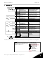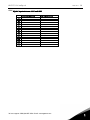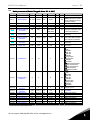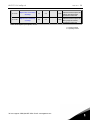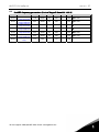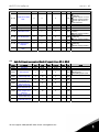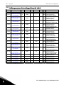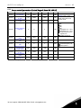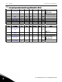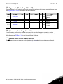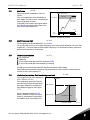
1
user's manual
nx frequency converters
APFIF131
Line Synchronization
application manual
VACON LINE SYNCHRONIZATION APPLICATION MANUAL
INDEX
Document code: ud1177
Software code: APFIF131V124
Date: 17.12.2009
1.
Introduction ................................................................................................................... 4
1.1
1.2
2.
General ........................................................................................................................................... 4
Connection example ...................................................................................................................... 5
Line synchro general ...................................................................................................... 6
2.1
2.2
2.3
2.4
2.5
2.6
Purpose .......................................................................................................................................... 6
Operation........................................................................................................................................ 6
Timing............................................................................................................................................. 7
Phase Offset To Net ....................................................................................................................... 8
Phase Hysteresis ........................................................................................................................... 8
Commissioning .............................................................................................................................. 9
3.
Version parameter comPATIBILITY ISSUES................................................................... 10
4.
Control I/O ................................................................................................................... 11
4.1
5.
Control signal logic in LineSynch Application ........................................................................... 12
“Terminal To Function” (TTF) programming principle ................................................... 13
5.1
5.2
5.3
6.
Defining an input/output for a certain function on keypad ....................................................... 13
Defining a terminal for a certain function with NCDrive programming tool ........................... 14
Defining unused inputs/outputs ................................................................................................. 15
LineSynch Application – Parameter lists....................................................................... 16
6.1
6.2
6.3
6.4
6.5
6.6
6.7
6.8
6.9
6.10
6.11
6.12
6.13
6.14
6.15
7.
Monitoring values (Control keypad: menu M1) ......................................................................... 16
Basic parameters (Control keypad: Menu M2 G2.1) ............................................................. 23
Input signals ................................................................................................................................ 24
Output signals.............................................................................................................................. 30
Drive control parameters (Control keypad: Menu M2 G2.4) ................................................ 36
Prohibit frequency parameters (Control keypad: Menu M2 G2.5) ....................................... 37
Motor control parameters (Control keypad: Menu M2 G2.6) ............................................... 38
Protections (Control keypad: Menu M2 G2.7) ....................................................................... 40
Auto fault reset parameters (Control keypad: Menu M2 G2.8) ............................................ 41
Fieldbus parameters (Control Keypad: Menu M2 G2.9) ........................................................ 42
Torque control parameters (Control Keypad: Menu M2 G2.10) ........................................... 43
Line Synch parameters (Control keypad: Menu M2 G2.12).................................................. 44
Keypad control (Control keypad: Menu M3) .............................................................................. 45
System menu (Control keypad: Menu M6) ................................................................................. 45
Expander boards (Control keypad: Menu M7) ........................................................................... 45
Description of parameters ............................................................................................ 46
7.1
7.2
8.
Synchronization Control Parameters ...................................................................................... 111
Keypad control parameters ...................................................................................................... 116
Appendices .................................................................................................................117
8.1
Parameters of motor thermal protection (ID’s 704 to 708): ................................................... 118
APFIF131 LineSynch
8.2
8.3
8.4
8.5
9.
vacon • 3
Parameters of Stall protection (ID’s 709 to 712): .................................................................... 118
Parameters of Underload protection (ID’s 713 to 716): .......................................................... 119
Fieldbus control parameters (ID’s 850 to 859) ........................................................................ 120
Line synchronization protection functions .............................................................................. 122
Fault codes .................................................................................................................125
24-hour support +358 (0)40 837 1150 • Email: [email protected]
4 • vacon
APFIF131 LineSynch
Line Synchronization Application
Software APFIF131
1.
INTRODUCTION
This application is mend to run a motor to net frequency and make contactor change so that the
motor is running directly from the network. This application supports up to eighth motors with own
I/O. The motors used can be of different sizes but the nominal voltage needs to be the same with all
motors. Line synchronization does not need additional chokes in output due to advanced control.
The drive can compensate for delays which are faced in contactors.
1.1
General
This application is not considered to be backwards combatable. Read the application change note or
the chapter in this application manual, “Version parameter compatibility issues” to see what needs
to be noted when updating the application. See also updated parameter description from NCDrive
when making commissioning.
The digital inputs and all the outputs are freely programmable and the application
supports all I/O-boards
Additional functions:
Line voltage monitoring
Line frequency monitoring
DC voltage monitoring
CANOpen I/O communication monitoring
Second ramps and S-shape ramp programming
Programmable Start/Stop and Reverse logic
DC-brake at start and stop
Three prohibit frequency areas
Programmable U/f curve and switching frequency
Autofaultreset funtion
Power limit functions
Different power limits for motoring and generating side
Different torque limits for motoring and generating side
Cooling monitor input from heat exchange unit
Possibility to connect the FB Process data to any parameter and some monitoring values
The parameters of the LineSynch Application are explained in Chapter 7 of this manual. The
explanations are arranged according to the individual ID number of the parameter.
1
Tel. +358 (0)201 2121 • Fax +358 (0)201 212 205
APFIF131 LineSynch
1.2
vacon • 5
Connection example
24-hour support +358 (0)40 837 1150 • Email: [email protected]
1
6 • vacon
2.
LINE SYNCHRO GENERAL
2.1
Purpose
APFIF131 LineSynch
This application is meant to run motor to net frequency and make contactor change that motor is
running directly from network.
2.2
Operation
The drive measures line voltage frequency and angle. When there is no synchronization command,
the application works as a normal Multi-Purpose application.
2.2.1 To Net
When synchronization command is given [P:ActiveSynchro (DI:HIGH)], frequency reference is
changed to net voltage frequency. When voltage frequency is within 0,10 Hz hysteresis with network
voltage frequency the drive will make small adjustments to frequency reference so that line voltage
angle and FC voltage angle are the same with given offset [P:PhaseOffSetToNet].
The drive remains at this synchronization until the command to end synchronization is given or the
command to change network is given [P:ActiveDirect] (DI:HIGH)]. When the command to go to the
network net is given (which can be given at the same time as synchronization command) thr
application checks for 40 ms that [P:PhaseHyst] is correct for change. When an internal decision is
made:
-
The drive stops modulation within given delay [P:DelayToCoasting].
The drive opens FC contactor within given delay [P:DelayToOpen].
The drive closed NET contactor within given delay [P:DelayToClose].
Drive remains in stop state until:
1. SingleMotorControl [P: ControlMode = 0 / Single Motor]
- [P:ActiveDirect] (DI:LOW)].
2. MultiMotorControl: [P: ControlMode = 1 - 3 / MultiMotor, InSecuence]
- Controller motor is changed:[P:ControlledMotor].
- Controlled motor control status is reset [P: Reset Direct]
2.2.2 To FC
When controlled motor is in net:
Drive waits for back to FC command [ResetDirect (HIGH)] or [ActiveDirect (LOW)].
When command is given drive:
-
Opens Net contactor immediately.
Closes FC Contactor within half of [P:StartDelayToFC] time.
Makes start within [P:StartDelayToFC] time. (Note restart delays)
Depending on the status of [P:ActiveSynchro], the drive will keep synchronization on start or follow
the given reference.
1
Tel. +358 (0)201 2121 • Fax +358 (0)201 212 205
APFIF131 LineSynch
2.3
vacon • 7
Timing
t1
t1
t2
t2
t1 = DelayToCoasting
t2 = DelayToOpen + contactor
mechanical delay
t3 =DelayToClose + contactor
mechanical delay
t3
t3 t4
Line voltage, FC voltage, Motor voltage and Motor current
t1: Application makes decision to change to the network, command to open FC contactor is
given.
t2: Drive stops modulation after delay [P:DelayToCoasting].
a. Motor BEM voltage starts to decrease.
b. Motor current goes to zero.
c. FC sees motor BEM voltage
t3: FC Contactor is mechanically open.
d. FC does not see motor voltage.
t4: NET contactor is mechanically closed
e. Motor voltage is the same as line voltage
f. Current goes to motor.
24-hour support +358 (0)40 837 1150 • Email: [email protected]
1
8 • vacon
2.4
APFIF131 LineSynch
Phase Offset To Net
PhaseOffSetToNet
Line voltage and FC voltage
2.5
Phase Hysteresis
2 x Phase Hysteresis
2 x Phase Hysteresis
Voltage angle reference and FC voltage hysteresis area
1
Tel. +358 (0)201 2121 • Fax +358 (0)201 212 205
APFIF131 LineSynch
2.6
vacon • 9
Commissioning
During commission delay parameters should be set according to these rules:
- The drive should not be in run state when NET contactor is closed.
- The FC Contactor should not open until the drive is in stop state
- NET and FC contactors can be closed at the same time for a short period if the drive is
not modulating.
During commissioning the following issues needs to be understood:
- Contactor delays may be from 3 ms up to 700 ms.
- NET and FC contactor delays may fluctuate from each other.
- Closing and opening delays may fluctuate.
- Contactor times may fluctuate even if application has same settings.
Use of interlocks:
- The NET contactor can not have an interlock from FC contactor.
o What can be used momentarily if contactor delays are not know
- The FC Contactor can have an interlock from net contactor.
- If DOL thermal protection is used this trip should be connected to ByPass interlock and
any situation that can cause motor input to interrupt.
Commissioning steps:
1. Use oscilloscope during commissioning.
a. Motor current
b. Line voltage
c. FC Voltage
d. Motor voltage
2. Make sure that the drive sees line voltages and frequency correctly.
a. V1.25.1 Line (main) voltage.
i. Only above 90% of motor nominal voltage is accepted.
b. V1.25.2 Line frequency voltage
i. Only positive frequency is accepted
3. Make sure that the direction of FC and NET is the same when synchronized.
a. Measure voltage between two phases from drive output and motor DOL input.
4. Make test runs without any load on motor shaft, if possible.
5. When the timing of system is known
a. Increase the coasting delay near the time when the FC contactor is mechanically
open.
b. Decrease or Increase Net contactor delays so that the opening of FC and the closing
of Net contactor happens right after modulation stops.
i. You may need to increase the modulation stop and FC opening delay if NET
contactor closing delay is long.
6. Recommended time for no current situation is about 20 ms.
a. Half of a cycle (5 ms) is the minimum due contactors aging.
7. Change [P:PhaseOffSetToNet] so that the motor BEM voltage and line voltage are at the
same position when the line contactor is mechanically closed.
TIP:
Adjusting field weakening point voltage higher so that motor BEM voltage is the same as line
voltage at the moment of closing the NET contactor this may decrease current spike.
24-hour support +358 (0)40 837 1150 • Email: [email protected]
1
10 • vacon
3.
APFIF131 LineSynch
VERSION PARAMETER COMPATIBILITY ISSUES
No compatibility issues.
1
Tel. +358 (0)201 2121 • Fax +358 (0)201 212 205
APFIF131 LineSynch
4.
vacon • 11
CONTROL I/O
Reference potentiometer, OPTA1
Terminal
1…10 k
mA
Signal
Reference voltage output
Analogue input 1.
Range 0-10V, Ri = 200
Range 0-20 mA Ri = 250
I/O Ground
Analogue input 2.
Range 0-10V, Ri = 200
Range 0-20 mA Ri = 250
Control voltage output
Description
Voltage for potentiometer, etc.
Analogue input 1 frequency reference.
Input range selected by jumpers.
Default range: Voltage 0 – 10 V
Ground for reference and controls
Analogue input 2 frequency reference
Input range selected by jumpers.
Default range: Current 0 – 20 mA
Voltage for switches, etc. max 0.1 A
I/O ground
Start forward
Programmable G2.2.7
Start reverse
Programmable G2.2.7
Fault reset
Programmable G2.2.7
Common for DIN 1—DIN 3
Control voltage output
I/O ground
Activate synchronization
Programmable G2.2.7
Activate change to net
Programmable G2.2.7
Ground for reference and controls
Contact closed = start forward
Programmable start logic P2.2.1
Contact closed = start reverse
Programmable logic P2.2.1
Contact open = no fault
Contact closed = fault
Connect to GND or +24V
Voltage for switches (see #6)
Ground for reference and controls
Drive will synchronize to net frequency and
angle.
Permission to make change to NET when
voltage is in synch.
CMB
AOA1+
AOA1-
Reset Network run
Programmable G2.2.7
Common for DIN4—DIN6
Analogue output 1
Programmable P2.3.1.2
DOA1
Digital output
Drive takes controlled motor off net.
(Multi motor control feature)
Connect to GND or +24V
Output range selected by jumpers.
Range 0—20 mA. RL, max. 500
Range 0—10 V. RL > 1k
Programmable
Open collector, I 50mA, U 48 VDC
1
2
+10Vref
AI1+
3
4
5
AI1AI2+
AI2-
6
+24V
7
8
GND
DIN1
9
DIN2
10
DIN3
11
12
13
14
CMA
+24V
GND
DIN4
15
DIN5
16
DIN6
17
18
19
20
OPTA2
220
VAC
21
22
23
RO1
RO1
RO1
Relay output 1
FC Contactor control
Programmable G2.3.3
24
25
26
RO2
RO2
RO2
Relay output 1
Net Contactor control
Programmable G2.3.3
Switching capacity
24 VCD / 8 A
250 VAC / 8 A
125 VDC / 0.4 A
Programmable
No function defined at default
Table 4-1. LineSynch application default I/O configuration and connection
example.
Note: See Users Manual, chapter Control Connections, for hardware specification and configuration.
Note: See jumper selections below.
More information in Vacon NX User's
Manual, Chapter 6.2.2.2.
Jumper block X 3 :
CM A a nd CM B grounding
CMB connected to GN D
CMA connected to GN D
CMB isolated from GN D
CMA isolated from GN D
CMB and CMA
internally connected together,
isolated from GN D
= Factory default
24-hour support +358 (0)40 837 1150 • Email: [email protected]
1
12 • vacon
4.1
APFIF131 LineSynch
Control signal logic in LineSynch Application
2.1.11 I/O Reference
2.1.12 Keypad Ctrl Reference
2.1.13 Fieldbus Ctrl Reference
2.1.15 Preset Speed 1
...2.1.21 Preset Speed 7
2.1.14 Jogging speed
reference
3.2 Keypad reference
DIN#
DIN#
DIN#
DIN#
Preset Speed 1
Preset Speed 2
Preset Speed 3
3.1 Control place
AI#
AIA#
AIA#
AI#
DIN#
Internal frequency
reference
Motor
Potentiometer
DIN#
Reference from fieldbus
Reset button
Start/Stop buttons
Start/Stop from fieldbus
Direction from fieldbus
DIN#
DIN#
Start forward
(programmable)
Start reverse (programmable)
Programmable
Start/Stop and
reverse logic
Start/Stop
Internal Start/Stop
Reverse
Internal reverse
3.3 Keypad direction
DIN#
Fault reset input
(programmable)
>1
Internal fault reset
NX12k103.fh8
Figure 4-1. Control signal logic of the LineSynch Application
1
Tel. +358 (0)201 2121 • Fax +358 (0)201 212 205
APFIF131 LineSynch
5.
vacon • 13
“TERMINAL TO FUNCTION” (TTF) PROGRAMMING PRINCIPLE
The programming principle of the input and output signals in the Multipurpose Control Application
NXP as well as in the Pump and Fan Control Application (and partly in the other applications) is
different compared to the conventional method used in other Vacon NX applications.
In the conventional programming method, Function to Terminal Programming Method (FTT), you
have a fixed input or output that you define a certain function for. The applications mentioned above,
however, use the Terminal to Function Programming method (TTF) in which the programming process is carried out the other way round: Functions appear as parameters which the operator defines
a certain input/output for. See Warning on page 14.
5.1
Defining an input/output for a certain function on keypad
Connecting a certain input or output with a certain function (parameter) is done by giving the
parameter an appropriate value. The value is formed of the Board slot on the Vacon NX control
board (see Vacon NX User's Manual, Chapter 6.2) and the respective signal number, see below.
READY
I/O term
AI Ref Faul/Warn
DigOUT:B.1
Function name
Slot
Terminal type
Terminal number
Example: You want to connect the digital output function Reference fault/warning (parameter
2.3.3.7) to the digital output DO1 on the basic board NXOPTA1 (see Vacon NX User's Manual, Chapter
6.2).
First find the parameter 2.3.3.7 on the keypad. Press the Menu button right once to enter the edit
mode. On the value line, you will see the terminal type on the left (DigIN, DigOUT, An.IN, An.OUT)
and on the right, the present input/output the function is connected to (B.3, A.2 etc.), or if not
connected, a value (0.#).
When the value is blinking, hold down the Browser button up or down to find the desired board slot
and signal number. The program will scroll the board slots starting from 0 and proceeding from A
to E and the I/O selection from 1 to 10.
Once you have set the desired value, press the Enter button once to confirm the change.
READY
I/Oterm
AI Ref Faul/Warn
DigOUT:0.0
READY
I/Oterm
AI Ref Faul/Warn
DigOUT:0.0
24-hour support +358 (0)40 837 1150 • Email: [email protected]
READY
I/Oterm
AI Ref Faul/Warn
DigOUT:B.1
enter
1
14 • vacon
5.2
APFIF131 LineSynch
Defining a terminal for a certain function with NCDrive programming tool
If you use the NCDrive Programming Tool for parametrizing you will have to establish the connection between the function and input/output in the same way as with the control panel. Just pick the
address code from the drop-down menu in the Value column (see the Figure below).
Figure 5-1. Screenshot of NCDrive programming tool; Entering the address code
!
WARNING
Be ABSOLUTELY sure not to connect two functions to one and same
output in order to avoid function overruns and to ensure flawless
operation.
Note: The inputs, unlike the outputs, cannot be changed in RUN state.
1
Tel. +358 (0)201 2121 • Fax +358 (0)201 212 205
APFIF131 LineSynch
5.3
vacon • 15
Defining unused inputs/outputs
All unused inputs and outputs must be given the board slot value 0 and the value 1 also for the
terminal number. The value 0.1 is also the default value for most of the functions. However, if you
want to use the values of a digital input signal for e.g. testing purposes only, you can set the board
slot value to 0 and the terminal number to any number between 2…10 to place the input to a TRUE
state. In other words, the value 1 corresponds to 'open contact' and values 2 to 10 to 'closed
contact'.
In case of analogue inputs, giving the value 1 for the terminal number corresponds to 0% signal
level, value 2 corresponds to 20%, value 3 to 30% and so on. Giving value 10 for the terminal number
corresponds to 100% signal level.
24-hour support +358 (0)40 837 1150 • Email: [email protected]
1
16 • vacon
6.
APFIF131 LineSynch
LINESYNCH APPLICATION – PARAMETER LISTS
On the next pages you will find the lists of parameters within the respective parameter groups. The
parameter descriptions are given on pages 46 to 116.
Column explanations:
Code
Parameter
Min
Max
Unit
Default
Cust
ID
_____
_____
_____
6.1
=
=
=
=
=
=
=
=
=
Location indication on the keypad; Shows the operator the present param. number
Name of parameter
Minimum value of parameter
Maximum value of parameter
Unit of parameter value; Given if available
Value preset by factory
Customer’s own setting
ID number of the parameter
On parameter code: Parameter value can only be changed after the FC has been
stopped.
= Apply the Terminal to Function method (TTF) to these parameters (see chapter 5)
= Monitoring value is possible to control from fieldbus by ID number
Monitoring values (Control keypad: menu M1)
The monitoring values are the actual values of parameters and signals as well as statuses and
measurements. See Vacon NX User's Manual, Chapter 7 for more information.
Code
V1.1
Parameter
Output frequency
V1.2
Frequency reference
V1.3
V1.4
V1.5
V1.6
V1.7
V1.8
V1.9
V1.10
V1.11
V1.12
V1.13
V1.14
V1.15
V1.16
V1.17
V1.18
V1.19
V1.20
Motor speed
Motor current
Motor torque
Motor Input Power
Motor voltage
DC link voltage
Unit temperature
Motor temperature
Analogue input 1
Analogue input 2
Analogue input 3
Analogue input 4
Analogue Out 1
Analogue Out 2
Analogue Out 3
DIN1, DIN2, DIN3
DIN4, DIN5, DIN6
Torque reference
Measured
temperature
V1.21
G1.22
Multimonitoring items
Table 6-1. Monitoring values
1
Unit
Hz
ID
1
Hz
25
rpm
A
%
kW
V
V
C
%
2
3
4
5
6
7
8
9
13
14
27
28
26
50
51
15
16
18
Cº
42
%
%
%
%
%
%
%
%
Description
Output frequency to motor
Frequency reference to motor
control
Motor speed in rpm
In % of Motor nominal torque
With one decimal accuracy
Heatsink temperature
Calculated motor temperature
AI1
AI2
AI3
AI4
AO1
AO2
AO3
Digital input statuses
Digital input statuses
Used Torque Reference
Highest temperature of OPTB8
board. 4 s filtering.
Displays three selectable
monitoring values
Tel. +358 (0)201 2121 • Fax +358 (0)201 212 205
APFIF131 LineSynch
vacon • 17
6.1.1 Monitoring values 2 (Control keypad: menu M1.24)
Code
V1.23.1
V1.23.2
V1.23.3
V1.23.4
V1.23.5
V1.23.6
V1.23.7
V1.23.8
V1.23.9
V1.23.10
V1.23.11
V1.23.12
V1.23.13
V1.23.14
Parameter
Current
Torque
DC Voltage
Status Word
Measured
temperature 1
Measured
temperature 2
Measured
temperature 3
ID Run Status
Analogue input 1
Analogue input 2
Analogue input 3
Analogue input 4
Final Frequency
Reference
Output power
Unit
A
%
V
ID
1113
1125
44
43
Cº
50
Cº
51
Cº
52
%
%
49
59
60
61
62
Hz
1131
kW
1508
%
%
Description
Unfiltered motor current
Unfiltered motor torque
Unfiltered DC link voltage
See chapter 6.1.6
AI1
AI2
AI3
AI4
Drive output power in kW
Table 6-2. Monitoring values 2
6.1.2 FieldBus Monitoring values (Control keypad: menu M1.24)
Code
V1.24.1
V1.24.2
V1.24.3
V1.24.4
V1.24.5
Parameter
FB Torque Reference
FB Limit Scaling
FB Adjust Reference
FB Analog Output
Last Active Fault
V1.24.6
FB Motor Current
V1.24.7
V1.24.8
V1.24.9
Din Status Word
Din Status Word 2
Last Active Warning
Unit
%
%
%
%
ID
1140
46
47
48
37
A
45
Description
Default Control of FB PD 1
Default Control of FB PD 2
Default Control of FB PD 3
Default Control of FB PD 4
Motor current (drive
independent) given with one
decimal point
56
57
74
Table 6-3. FieldBus Monitoring values
24-hour support +358 (0)40 837 1150 • Email: [email protected]
1
18 • vacon
APFIF131 LineSynch
6.1.3 Synch Monitoring values (Control keypad: menu M1.25)
Code
V1.25.1
Parameter
Line Voltage
Line Voltage
Frequency
Unit
V
ID
1650
Hz
1654
V1.25.3
Phase error
Dec
1659
V1.25.4
Synchronization Status
1651
V1.25.5
Contactor Status
1652
V1.25.2
V1.25.6
V1.25.7
V1.25.8
V1.25.9
V1.25.10
FB Synchronization
control
Controlled Motor
Line voltage L1 – L2
Line voltage L2 – L3
Line voltage L3 – L1
1640
V
V
V
1641
1655
1656
1657
Description
OPT-D7 measured line voltage
OPT-D7 measured line voltage
frequency
Phase error in Dec. from
reference.
Synchronization status for
NCDrive in CAN communication.
Values are updated at 1 ms
interval.
Relay control status from
application
Line Synchronization control
Word from fieldbus.
Real time
Real time
Real time
Table 6-4. Synchro Monitoring values
27
Analogue Input 3
28
Analogue Input 4
It’s possible to adjust this input value from fieldbus when ID 141 values is 0.1. That way
its possible to adjust Free Analogue input from fieldbus and have all analogue inputs
function available for fieldbus process datas. See also ID 1509.
46
FB Limit Scaling
47
FB Adjust Reference
48
FB Analogue Output
1140
FB Torque Reference
These are default controlling signals from LineSynch application. If these functions are
not needed it’s possible to free these input to control some other parameter or
monitoring value.
6.1.4 Digital input statuses: ID15 and ID16
b0
b1
b2
1
DIN1/DIN2/DIN3 status
DIN3
DIN2
DIN1
DIN4/DIN5/DIN6 status
DIN6
DIN5
DIN4
Tel. +358 (0)201 2121 • Fax +358 (0)201 212 205
APFIF131 LineSynch
vacon • 19
6.1.5 Digital input statuses: ID56 and ID57
b0
b1
b2
b3
b4
b5
b6
b7
b8
b9
b10
b11
b12
b13
b14
b15
DIN StatusWord 1
DIN: A.1
DIN: A.2
DIN: A.3
DIN: A.4
DIN: A.5
DIN: A.6
DIN: B.1
DIN: B.2
DIN: B.3
DIN: B.4
DIN: B.5
DIN: B.6
DIN: C.1
DIN: C.2
DIN: C.3
DIN: C.4
DIN StatusWord 2
DIN: C.5
DIN: C.6
DIN: D.1
DIN: D.2
DIN: D.3
DIN: D.4
DIN: D.5
DIN: D.6
DIN: E.1
DIN: E.2
DIN: E.3
DIN: E.4
DIN: E.5
DIN: E.6
24-hour support +358 (0)40 837 1150 • Email: [email protected]
1
20 • vacon
APFIF131 LineSynch
6.1.6 Application Status Word
Application Status Word combains different drive statuses to one data word.
See monitoring value V1.23.4 Status Word.
Application Status Word ID43
FALSE
TRUE
b0
b1
b2
b3
Not in Ready state
Not Running
No Fault
Ready
Running
Fault
b4
b5
b6
b7
Emergency stop not active
Run Disabled
No Warning
Emergency stop active
Run Enable
Warning
No DC Brake
FC Contacto feedback
Motor is synchronized with NET
NET Contactor feedback
DC Brake is active
No Run Request
No Limit Controls Active
External Brake Control OFF
Run Request
Limit control Active
External Brake Control ON
b8
b9
b10
b11
b12
b13
b14
b15
Table 6-5. Application Status Word Content.
6.1.7 Synchronization Status Word: ID1651
Signal
Line Synch Status Word
Comment
b0
b1
b2
b3
Drive Ready
Drive Run
Active Synchro
Fine tuning Start
Drive is in Ready state
Drive is in Run state
Command to make synchronization is active
Line voltage frequency within 0,10 Hz from net frequency
b4
b5
b6
b7
Fine tuning OK
Active Direct
FC Active
Connect Direct
Voltage angle is within hysteresis
Command to change to net is active
Final control signal to FC relay
Internal command to close NET contactor
b8
b9
b10
b11
Direct Active
Final control signals to NET relay
b12
b13
b14
b15
Table 6-6. Line Sync Status Word.
1
Tel. +358 (0)201 2121 • Fax +358 (0)201 212 205
APFIF131 LineSynch
vacon • 21
6.1.8 Contactor status Word
Status of the relay outputs.
Signal
b0
b1
b2
b3
Motor 1 FC Contactor
Motor 1 NET Contactor
Motor 2 FC Contactor
Motor 2 NET Contactor
b4
b5
b6
b7
Motor 3 FC Contactor
Motor 3 NET Contactor
Motor 4 FC Contactor
Motor 4 NET Contactor
b8
b9
b10
b11
Motor 5 FC Contactor
Motor 5 NET Contactor
Motor 6 FC Contactor
Motor 6 NET Contactor
b12
b13
b14
b15
Motor 7 FC Contactor
Motor 7 NET Contactor
Motor 8 FC Contactor
Motor 8 NET Contactor
Contactor Status Word ID1652
Comment
Table 6-7. Line Synch Control Word
6.1.9 FB Line Synchronization control word
FieldBus Line synchronization control word
Signal
Comment
b0
b1
b2
b3
Activate synchronization
Activate changeover to DOL
Reset DOL contactor(s)
b4
Single Start
b5
Single to net
b6
Single reset
Drive will synchronize to net frequency
Drive will make change to DOL when synchronized
Drive will open closed net contactor(s)
Drive will not start automatically to next motor, rising
edge start command required in FB control.
Drive will not make changeover to DOL automatically,
rising edge for synchronization and changeover
required. (ID1700.B1)
Rising edge of Reset DOL will open only one NET
contactor. (ID1700.B3)
b7
b8
Motor Bx control
b9
Start in sequence
B12 to 14 are used to select controlled motor in FB
control.
Drive will put all motors to net while B0-B2 are active,
cannot be used at the same time with B8.
b10
b11
b12
b13
b14
b15
Motor select B0
Motor select B1
Motor select b2
Table 6-8. Line Synch Control Word
24-hour support +358 (0)40 837 1150 • Email: [email protected]
1
22 • vacon
6.1.10
APFIF131 LineSynch
Recommended signals for NCDrive
In NCDrive use binary mode to monitor Application Status Word
*.trn, *.par and Print Service info to file (*.txt) with situation description.
Tell at least application ID and version number.
To access Parameter help: Select parameter and press F1
1
Tel. +358 (0)201 2121 • Fax +358 (0)201 212 205
APFIF131 LineSynch
6.2
vacon • 23
Basic parameters (Control keypad: Menu M2
G2.1)
Code
P2.1.1
Parameter
Min frequency
Min
0,00
Max
Par. 2.1.2
Unit
Hz
Default
0,00
P2.1.2
Max frequency
Par. 2.1.1
320,00
Hz
50,00
102
P2.1.3
P2.1.4
P2.1.5
Acceleration time 1
Deceleration time 1
Current limit
0,1
0,1
0,1 x IH
3000,0
3000,0
2 x IH
s
s
A
103
104
107
P2.1.6
Nominal voltage of
the motor
180
690
V
3,0
3,0
IL
NX2: 230V
NX5: 400V
NX6: 690V
P2.1.7
Nominal frequency
of the motor
8,00
320,00
Hz
50,00
111
P2.1.8
Nominal speed of
the motor
24
20 000
rpm
1440
112
P2.1.9
Nominal current of
the motor
0,1 x IH
2 x IH
A
IH
113
P2.1.10
Motor cos
0,30
1,00
0,85
120
P2.1.11
I/O Reference
0
14
0
117
P2.1.12
Keypad control
reference
0
9
8
121
0
9
9
122
See par. 2.1.12
0,00
Par. 2.1.2
Hz
5,00
124
See ID413.
0,00
0,00
0,00
0,00
0,00
0,00
0,00
Par. 2.1.2
Par. 2.1.2
Par. 2.1.2
Par. 2.1.2
Par. 2.1.2
Par. 2.1.2
Par. 2.1.2
Hz
Hz
Hz
Hz
Hz
Hz
Hz
10,00
15,00
20,00
25,00
30,00
40,00
50,00
105
106
126
127
128
129
130
Multi-step speed 1
Multi-step speed 2
Multi-step speed 3
Multi-step speed 4
Multi-step speed 5
Multi-step speed 6
Multi-step speed 7
P2.1.13
P2.1.14
P2.1.15
P2.1.16
P2.1.17
P2.1.18
P2.1.19
P2.1.20
P2.1.21
Fieldbus control
reference
Jogging speed
reference
Preset speed 1
Preset speed 2
Preset speed 3
Preset speed 4
Preset speed 5
Preset speed 6
Preset speed 7
Cust
ID
101
110
Note
Used is + 0,75 Hz
NOTE: If fmax > than the
motor synchronous speed,
check suitability for motor
and drive system
0 Hz to Max frequency
Max frequency to 0 Hz
Check the rating plate of
the motor. Note also used
connection Delta/Star.
Check the rating plate of
the motor
The default applies for a 4pole motor and a nominal
size frequency converter.
Check the rating plate of
the motor.
Check the rating plate of
the motor
0=AI1
1=AI2
2=AI1+AI2
3=AI1-AI2
4=AI2-AI1
5=AI1xAI2
6=AI1 Joystick
7=AI2 Joystick
8=Keypad
9=Fieldbus
10=Motor potentiometer
11=AI1, AI2 minimum
12=AI1, AI2 maximum
13=Max frequency
14=AI1/AI2 selection
0=AI1
1=AI2
2=AI1+AI2
3=AI1-AI2
4=AI2-AI1
5=AI1xAI2
6=AI1 Joystick
7=AI2 Joystick
8=Keypad
9=Fieldbus
Table 6-9. Basic parameters G2.1
24-hour support +358 (0)40 837 1150 • Email: [email protected]
1
24 • vacon
6.3
APFIF131 LineSynch
Input signals
6.3.1 Basic Settings (Control keypad: Menu M2
Code
P2.2.1.1
Parameter
Start/Stop logic
selection
Min
0
Max
Unit
7
G2.2.1)
Default
Cust
0
ID
300
0
1
2
3
4
5
6
7
Motor potentiometer
P2.2.1.2
ramp time
0,1
2000,0
Hz/s
10,0
Start
signal 2
(Default:
DIN2)
Start fwd
Start/Stop
Start/Stop
Start pulse
Start
Start fwd*
Start*/Stop
Start*/Stop
Start rvs
Reverse
Run enable
Stop pulse
Mot.pot.UP
Start rvs*
Reverse
Run enable
331
Motor potentiometer
P2.2.1.3 frequency reference
memory reset
0
2
1
367
P2.2.1.4
Adjust input
0
5
0
493
P2.2.1.5
P2.2.1.6
Adjust minimum
Adjust maximum
0,0
0,0
100,0
100,0
0,0
0,0
494
495
%
%
Note
Start
signal 1
(Default:
DIN1)
0=No reset
1=Reset if stopped or
powered down
2=Reset if powered down
0=Not used
1=AI1
2=AI2
3=AI3
4=AI4
5=Fieldbus (see group G2.9)
Table 6-10. Input signals: basic settings, G2.2.1
6.3.2 Analogue input 1 (Control keypad: Menu M2
Code
P2.2.2.2
Parameter
AI1 signal
selection
AI1 filter time
P2.2.2.3
AI1 signal range
P2.2.2.1
P2.2.2.4
P2.2.2.5
P2.2.2.6
P2.2.2.7
P2.2.2.8
AI1 custom
minimum setting
AI1 custom
maximum setting
AI1 reference
scaling, minimum
value
AI1 reference
scaling, maximum
value
AI1 joystick
hysteresis
Min
Max
0.1
E.10
0,00
10,00
0
3
-160,00
160,00
-160,00
Default
Cust
ID
A.1
377
0,10
324
0
320
%
0,00
321
160,00
%
100,00
322
0,00
320,00
Hz
0,00
303
0,00
320,00
Hz
0,00
304
0,00
20,00
%
0,00
384
s
P2.2.2.9
AI1 sleep limit
0,00
100,00
%
0,00
385
P2.2.2.10
AI1 sleep delay
0,00
320,00
s
0,00
386
P2.2.2.11
AI1 joystick offset
-100,00
100,00
%
0,00
165
Table 6-11. Analogue input 1 parameters, G2.2.2
1
Unit
G2.2.2)
Note
TTF programming. See
chapter 5
0=No filtering
0=0-10 V (0-20 mA*)
1=2-10 V (4-20 mA*)
2= -10V…+10V*
3= Custom range*
% of input signal range.
e.g.3 V = 30 %
e.g.9 V = 90 %
Selects the frequency that
corresponds to the min.
reference signal
Selects the frequency that
corresponds to the max.
reference signal
Dead zone for joystick
input
Drive goes to sleep mode
if input is below this limit
for set time.
Press ‘Enter’ for 1s to set
offset, ‘Reset’ to set 0,00
*Remember to place jumpers of block X2 accordingly.
See the product's User's Manual
Tel. +358 (0)201 2121 • Fax +358 (0)201 212 205
APFIF131 LineSynch
24-hour support +358 (0)40 837 1150 • Email: [email protected]
vacon • 25
1
26 • vacon
APFIF131 LineSynch
6.3.3 Analogue input 2 (Control keypad: Menu M2
Code
P2.2.3.2
Parameter
AI2 signal
selection
AI2 filter time
P2.2.3.3
AI2 signal range
P2.2.3.1
P2.2.3.4
P2.2.3.5
P2.2.3.6
P2.2.3.7
P2.2.3.8
AI2 custom
minimum setting
AI2 custom
maximum setting
AI2 reference
scaling, minimum
value
AI2 reference
scaling, maximum
value
AI2 joystick
hysteresis
Min
Max
0.1
E.10
0,00
10,00
0
3
-160,00
160,00
-160,00
Unit
G2.2.3)
Default
Cust
ID
A.2
388
0,10
329
1
325
%
20,00
326
160,00
%
100,00
327
0,00
320,00
Hz
0,00
393
0,00
320,00
Hz
0,00
394
0,00
20,00
%
0,00
395
s
P2.2.3.9
AI2 sleep limit
0,00
100,00
%
0,00
396
P2.2.3.10
AI2 sleep delay
0,00
320,00
s
0,00
397
P2.2.3.11
AI2 joystick offset
-100,00
100,00
%
0,00
166
Note
TTF programming. See
chapter 5
0=No filtering
0=0-20 mA (0-10 V *)
1=4-20 mA (2-10 V *)
2= -10V…+10V*
3= Custom range*
% of input signal range.
e.g. 2 mA = 10 %
e.g. 18 mA = 90 %
Selects the frequency that
corresponds to the min.
reference signal
Selects the frequency that
corresponds to the max.
reference signal
Dead zone for joystick
input, e.g. 10 % = +/- 5 %
Drive goes to sleep mode
if input is below this limit
for set time.
Press ‘Enter’ for 1s to set
offset, ‘Reset’ to set 0,00
Table 6-12. Analogue input 2 parameters, G2.2.3
6.3.4 Analogue input 3 (Control keypad: Menu M2
Code
P2.2.4.2
Parameter
AI3 signal
selection
AI3 filter time
P2.2.4.3
AI3 signal range
P2.2.4.1
P2.2.4.4
P2.2.4.5
P2.2.4.6
AI3 custom
minimum setting
AI3 custom
maximum setting
AI3 signal inversion
Min
Max
0.1
E.10
0,00
10,00
0
3
-160,00
160,00
-160,00
160,00
0
1
Unit
G2.2.4)
Default
Cust
ID
Note
TTF programming. See
chapter 5
0=No filtering
0=0-20 mA (0-10 V *)
1=4-20 mA (2-10 V *)
2= -10V…+10V*
3= Custom range*
% of input signal range.
e.g. 2 mA = 10 %
0.1
141
0,00
142
0
143
%
0,00
144
%
100,00
145
e.g. 18 mA = 90 %
0
151
0=Not inverted
1=Inverted
s
Table 6-13. Analogue input 3 parameters, G2.2.4
*Remember to place jumpers of block X2 accordingly.
See the product's User's Manual.
1
Tel. +358 (0)201 2121 • Fax +358 (0)201 212 205
APFIF131 LineSynch
vacon • 27
6.3.5 Analogue input 4 (Control keypad: Menu M2
Code
P2.2.5.2
Parameter
AI4 signal
selection
AI4 filter time
P2.2.5.3
AI4 signal range
P2.2.5.1
P2.2.5.4
P2.2.5.5
P2.2.5.6
AI4 custom
minimum setting
AI4 custom
maximum setting
AI4 signal inversion
Min
Max
0.1
E.10
0,00
10,00
0
3
-160,00
160,00
-160,00
160,00
0
1
Unit
G2.2.5)
Default
Cust
ID
Note
TTF programming. See
chapter 5
0=No filtering
0=0-20 mA (0-10 V *)
1=4-20 mA (2-10 V *)
2= -10V…+10V*
3= Custom range*
% of input signal range.
e.g. 2 mA = 10 %
0.1
152
0,00
153
1
154
%
20,00
155
%
100,00
156
e.g. 18 mA = 90 %
0
162
0=Not inverted
1=Inverted
s
Table 6-14. Analogue input 4 parameters, G2.2.5
6.3.6 Free analogue input, signal selection (Keypad: Menu M2
Code
P2.2.6.1
Parameter
Scaling of current
limit
Unit
Default
Cust
G2.2.6)
Min
Max
ID
0
5
0
399
P2.2.6.2
Scaling of DC-braking
current
0
5
0
400
P2.2.6.3
Scaling of acc./dec.
times
0
5
0
401
P2.2.6.4
Scaling of torque
supervision limit
0
5
0
402
0
5
0
485
0
5
0
1087
0
5
0
179
0
5
0
1088
P2.2.6.5 Scaling of torque limit
P2.2.6.6
P2.2.6.7
P2.2.6.8
Scaling of generator
torque limit
Scaling of motoring
power limit
Scaling of generator
power limit
Note
0=Not used
1=AI1
2=AI2
3=AI3
4=AI4
5=FB Limit Scaling
See group G2.9
As parameter P2.2.6.1
Scaling from 0 to ID507
As parameter P2.2.6.1
Scales active ramp from
100 % to 10 %.
As parameter P2.2.6.1
Scaling from 0 to ID348
As parameter P2.2.6.1
Scaling from 0 to (ID609
(NXS) or ID1287 (NXP))
As parameter P2.2.6.1
Scaling from 0 to ID1288
As parameter P2.2.6.1
Scaling from 0 to ID1289
As parameter P2.2.6.1
Scaling from 0 to ID1290
Table 6-15. Free analogue input signal selection, G2.2.6
24-hour support +358 (0)40 837 1150 • Email: [email protected]
1
28 • vacon
APFIF131 LineSynch
6.3.7 Digital inputs (Control keypad: Menu M2
G2.2.4)
Use TTF programming method for all these parameters. See chapter 5.
Code
P2.2.7.1
P2.2.7.2
P2.2.7.3
Parameter
Start signal 1
Start signal 2
Run enable
Min
0.1
0.1
0.1
Default
A.1
A.2
0.2
P2.2.7.4
Reverse
0.1
0.1
412
P2.2.7.5
P2.2.7.6
P2.2.7.7
0.1
0.1
0.1
0.1
0.1
0.1
419
420
421
0.1
0.1
417
0.1
0.1
418
P2.2.7.10
P2.2.7.11
P2.2.7.12
Preset speed 1
Preset speed 2
Preset speed 3
Motor potentiometer
reference DOWN
Motor potentiometer
reference UP
Fault reset
External fault (close)
External fault (open)
0.1
0.1
0.1
A.3
0.1
0.2
414
405
406
P2.2.7.13
Acc/Dec time selection
0.1
0.1
408
P2.2.7.14
P2.2.7.15
Acc/Dec prohibit
DC braking
0.1
0.1
0.1
0.1
415
416
P2.2.7.16
Jogging speed
0.1
0.1
413
P2.2.7.8
P2.2.7.9
ID
403
404
407
P2.2.7.17
AI1/AI2 selection
0.1
0.1
422
P2.2.7.18
Control from I/O terminal
0.1
0.1
409
P2.2.7.19
Control from keypad
0.1
0.1
410
P2.2.7.20
Control from fieldbus
0.1
0.1
411
P2.2.7.21
Parameter set 1/set 2
selection
0.1
0.1
496
P2.2.7.22
Motor control mode 1/2
0.1
0.1
164
P2.2.7.23
P2.2.7.24
Cooling monitor
Enable inching
0.1
0.1
0.2
0.1
750
532
P2.2.7.25
Inching reference 1
0.1
0.1
530
P2.2.7.26
Inching reference 2
0.1
0.1
531
P2.2.7.27
Emergency stop
Input switch
acknowledgement
Active synchronization
Active direct
Reset direct
FC Contactor acknowledge
Net contactor
acknowledge
Motor selection B0
Motor selection B1
Motor selection B2
0.1
0.2
1213
0.1
0.2
1209
0.1
0.1
0.1
0.1
A.4
A.5
A.6
0.1
I600
1601
1612
1630
0.1
0.1
1631
0.1
0.1
0,1
0,1
0.1
0.1
1670
1671
1672
P2.2.7.28
P2.2.7.29
P2.2.7.30
P2.2.7.31
P2.2.7.32
P2.2.7.33
P2.2.7.34
P2.2.7.35
P2.2.7.36
1
Cust
Note
See P2.2.1.1.
See P2.2.1.1.
Motor start enabled (cc)
Direction forward (oc)
Direction reverse (cc)
See preset speeds in Basic
Parameters (G2.1)
Mot.pot. reference decreases
(cc)
Mot.pot. reference increases
(cc)
All faults reset (cc)
Ext. fault (F51) displayed (cc)
Ext. fault (F51) displayed (oc)
Acc/Dec time 1 (oc)
Acc/Dec time 2 (cc)
Acc/Dec prohibited (cc)
DC braking active (cc)
Jogging speed selected for
frequency reference (cc)
cc = AI2 is used as reference,
when ID117 = 14
Force control place to I/O
terminal (cc)
Force control place to
keypad (cc)
Force control place to
fieldbus (cc)
Closed cont.=Set 2 is used
Open cont.=Set 1 is used
Closed cont.=Mode 2 is used
Open cont.=Mode 1 is used
See par 2.6.1, 2.6.12
Used with liquid-cooled unit
Enables Inching function
Inching reference 1. (Default
Forward 2 Hz. See P2.4.16)
This will start the drive
Inching reference 2. (Default
Forward 2 Hz. See P2.4.17)
This will start the drive
Low signal activates EM
Low signal generates fault
(F64)
Tel. +358 (0)201 2121 • Fax +358 (0)201 212 205
APFIF131 LineSynch
vacon • 29
P2.2.7.37
ByPass Inter Lock Falling
(OC) Edge
0,1
0.2
1636
P2.2.7.38
ByPass Inter Lock Rising
(CC) Edge
0,1
0.1
1637
Interlock from device that
monitors if motor input is OK.
Falling edge will activate
protection function F87.
Interlock from device that
monitors if motor input is OK.
Rising edge will activate
protection function F87.
Table 6-16. Digital input signals, G2.2.4
cc = closing contact
oc = opening contact
24-hour support +358 (0)40 837 1150 • Email: [email protected]
1
30 • vacon
6.4
APFIF131 LineSynch
Output signals
6.4.1 Delayed digital output 1 (Keypad: Menu M2
Code
Parameter
Min
Max
P2.3.1.1
Digital output 1
signal selection
0.1
E.10
0.1
486
P2.3.1.2
Digital output 1
function
0
26
1
312
0,00
320,00
s
0,00
487
0,00 = On delay not in use
0,00
320,00
s
0.00
488
0,00 = Off delay not in use
ID
Note
TTF programming. See
chapter 5.
Possible to invert with
ID1084 (NXP only)
P2.3.1.3
P2.3.1.4
Digital output 1 on
delay
Digital output 1 off
delay
Unit
G2.3.1)
Default
Cust
ID
Note
TTF programming. See
chapter 5.
Possible to invert with
ID1084 (NXP only)
0=Not used
1=Ready
2=Run
3=Fault
4=Fault inverted
5=FC overheat warning
6=Ext. fault or warning
7=Ref. fault or warning
8=Warning
9=Reverse
10=Jogging spd selected
11=At speed
12=Mot. regulator active
13=Freq. limit 1 superv.
14=Freq. limit 2 superv.
15=Torque limit superv.
16=Ref. limit supervision
17=Not used
18=I/O control place act.
19=FC temp. limit superv.
20=Reference inverted
21=Not used
22=Therm. fault or warn.
23=AI supervision
24=Fieldbus DIN 1
25=Fieldbus DIN 2
26=Fieldbus DIN 3
Table 6-17. Delayed digital output 1 parameters, G2.3.1
6.4.2 Delayed digital output 2 (Keypad: Menu M2
Code
Parameter
Min
Max
P2.3.2.1
Digital output 2
signal selection
0.1
E.10
0.1
489
0
26
0
490
See par. 2.3.1.2
0,00
320,00
s
0,00
491
0,00 = On delay not in use
0,00
320,00
s
0,00
492
0,00 = Off delay not in use
P2.3.2.2
P2.3.2.3
P2.3.2.4
Digital output 2
function
Digital output 2 on
delay
Digital output 2 off
delay
Unit
G2.3.2)
Default
Cust
Table 6-18. Delayed digital output 2 parameters, G2.3.2
1
Tel. +358 (0)201 2121 • Fax +358 (0)201 212 205
APFIF131 LineSynch
vacon • 31
6.4.3 Digital output signals (Control keypad: Menu M2
G2.3.3)
Use TTF programming method for all these parameters. See chapter 5.
Code
P2.3.3.1
P2.3.3.2
P2.3.3.3
P2.3.3.4
P2.3.3.5
P2.3.3.6
Min
0.1
0.1
0.1
0.1
0.1
0.1
Default
A.1
0.1
0.1
0.1
0.1
0.1
0.1
0.1
438
0.1
0.1
439
P2.3.3.9
Parameter
Ready
Run
Fault
Inverted fault
Warning
External fault
Reference
fault/warning
Overtemperature
warning
Reverse
0.1
0.1
440
P2.3.3.10
Unrequested direction
0.1
0.1
441
P2.3.3.11
At speed
0.1
0.1
442
P2.3.3.12
Jogging speed
0.1
0.1
443
P2.3.3.13
P2.3.3.14
I/O control place
External brake control
External brake control,
inverted
Output frequency limit
1 supervision
Output frequency limit
2 supervision
Reference limit
supervision
Temperature limit
supervision
Torque limit
supervision
Themistor fault or
warning
Analogue input
supervision limit
Motor regulator
activation
Fieldbus DIN 1
Fieldbus DIN 2
Fieldbus DIN 3
Fieldbus DIN 4
Fieldbus DIN 5
DC ready pulse
Safe Disable Active
Drive in Synch
Motor 1 FC Control
Motor 1 DL Control
Motor 2 FC Control
Motor 2 DL Control
Motor 3 FC Control
Motor 3 DL Control
Motor 4 FC Control
Motor 4 DL Control
Motor 5 FC Control
Motor 5 DL Control
0.1
0.1
0.1
0.1
444
445
0.1
0.1
446
0.1
0.1
447
See ID315.
0.1
0.1
448
See ID346.
0.1
0.1
449
See ID350.
0.1
0.1
450
Drive temperature
supervision. See ID354.
0.1
0.1
451
See ID348.
0.1
0.1
452
0.1
0.1
463
0.1
0.1
454
0.1
0.1
0.1
0.1
0.1
0.1
0.1
0.1
0.1
0.1
0.1
0.1
0.1
0.1
0.1
0.1
0.1
0.1
0.1
0.1
0.1
0.1
0.1
0.1
0.1
0.1
B.1
B.2
0.1
0.1
0.1
0.1
0.1
0.1
0.1
0.1
455
456
457
169
170
1218
756
1625
1602
1603
1604
1605
1606
1607
1615
1616
1617
1618
P2.3.3.7
P2.3.3.8
P2.3.3.15
P2.3.3.16
P2.3.3.17
P2.3.3.18
P2.3.3.19
P2.3.3.20
P2.3.3.21
P2.3.3.22
P2.3.3.23
P2.3.3.24
P2.3.3.25
P2.3.3.26
P2.3.3.27
P2.3.3.28
P2.3.3.29
P2.3.3.30
P2.3.3.31
P2.3.3.32
P2.3.3.33
P2.3.3.34
P2.3.3.35
P2.3.3.36
P2.3.3.37
P2.3.3.38
P2.3.3.39
P2.3.3.40
P2.3.3.41
Cust
24-hour support +358 (0)40 837 1150 • Email: [email protected]
ID
432
433
434
435
436
437
Note
Ready to Run
Running
Drive in fault state
Drive not in fault state
Warning active
External fault active
4 mA fault or warning
active
Drive overtemperature
active
Output frequency < 0 Hz
Actual direction <>
requested direction
Reference = Output
frequency
Jogging or preset speed
command active
IO control active
See explanations on page
See ID356
See fieldbus manual
See fieldbus manual
See fieldbus manual
See fieldbus manual
See fieldbus manual
For external DC charger
1
32 • vacon
P2.3.3.42
P2.3.3.43
P2.3.3.44
P2.3.3.45
P2.3.3.46
P2.3.3.47
APFIF131 LineSynch
Motor 6 FC Control
Motor 6 DL Control
Motor 7 FC Control
Motor 7 DL Control
Motor 8 FC Control
Motor 8 DL Control
0.1
0.1
0.1
0.1
0.1
0.1
0.1
0.1
0.1
0.1
0.1
0.1
1645
1646
1617
1648
1664
1665
Table 6-19. Digital output signals, G2.3.3
!
WARNING
1
Be ABSOLUTELY sure not to connect two functions to one and
same output in order to avoid function overruns and to ensure
flawless operation.
Tel. +358 (0)201 2121 • Fax +358 (0)201 212 205
APFIF131 LineSynch
vacon • 33
6.4.4 Limit settings (Control keypad: Menu M2
Code
Parameter
Min
Max
P2.3.4.1
Output frequency
limit 1 supervision
0
2
P2.3.4.2
Output frequency
limit 1;
Supervised value
0,00
320,00
P2.3.4.3
Output frequency
limit 2 supervision
0
2
P2.3.4.4
Output frequency
limit 2;
Supervised value
0,00
320,00
P2.3.4.5
Torque limit
supervision
0
2
P2.3.4.6
Torque limit
supervision value
-300,0
300,0
P2.3.4.7
Reference limit
supervision
0
2
P2.3.4.8
Reference limit
supervision value
0,0
100,0
P2.3.4.9
FC temperature
supervision
0
2
P2.3.4.10
FC temperature
supervised value
–10
100
P2.3.4.11
P2.3.4.12
P2.3.4.13
Analogue
supervision signal
Analogue supervision low limit
Analogue supervision high limit
0
4
0,00
100,00
0,00
100,00
G2.3.4)
Unit
Hz
Hz
%
%
C
Default
Cust
ID
0
315
0,00
316
0
346
0,00
347
0
348
100,0
349
0
350
0,0
351
0
354
40
355
Note
0=Not used
1=Low limit supervision
2=High limit supervision
0=Not used
1=Low limit supervision
2=High limit supervision
0=Not used
1=Low limit supervision
2=High limit supervision
For brake control
absolute values are used
0=Not used
1=Low limit
2=High limit
0,0=Min frequency
100,0=Max frequency
0=Not used
1=Low limit
2=High limit
0
356
0=Not used
1=AI1
2=AI2
3=AI3
4=AI4
%
10,00
357
DO Off limit. See P2.3.3.22
%
90,00
358
DO Off limit. See P2.3.3.22
Table 6-20. Limit settings, G2.3.4
24-hour support +358 (0)40 837 1150 • Email: [email protected]
1
34 • vacon
APFIF131 LineSynch
6.4.5 Analogue output 1 (Control keypad: Menu M2
Code
P2.3.5.1
P2.3.5.2
P2.3.5.3
P2.3.5.4
P2.3.5.5
P2.3.5.6
P2.3.5.7
Parameter
Analogue output 1
signal selection
Analogue output 1
function
Analogue output 1
filter time
Analogue output 1
inversion
Analogue output 1
minimum
Analogue output 1
scale
Analogue output 1
offset
Unit
G2.3.5)
Min
Max
0.1
E.10
A.1
464
0
15
1
307
0,00
10,00
1,00
308
0
1
0
309
0
1
0
310
10
1000
%
100
311
-100,00
100,00
%
0,00
375
s
Default
Cust
ID
Note
TTF programming. See
chapter 5.
0=Not used (20 mA / 10 V)
1=Output freq. (0—fmax)
2=Freq. reference (0—fmax)
3=Motor speed (0—Motor
nominal speed)
4=Motor current (0—InMotor)
5=Motor torque (0—TnMotor)
6=Motor power (0—PnMotor)
7=Motor voltage (0-UnMotor)
8=DC-link volt (0—1000V)
9=AI1
10=AI2
11=Output freq. (fmin - fmax)
12=Motor torque
(–2…+2xTNmot)
13=Motor power
(–2…+2xTNmot)
14=PT100 temperature
15=FB analogue output
ProcessData4 (NXS)
0=No filtering
0=Not inverted
1=Inverted
0=0 mA (0 V)
1=4 mA (2 V)
Table 6-21. Analogue output 1 parameters, G2.3.5
6.4.6 Analogue output 2 (Control keypad: Menu M2
Code
P2.3.6.1
P2.3.6.2
P2.3.6.3
P2.3.6.4
P2.3.6.5
P2.3.6.6
P2.3.6.7
Parameter
Analogue output 2
signal selection
Analogue output 2
function
Analogue output 2
filter time
Analogue output 2
inversion
Analogue output 2
minimum
Analogue output 2
scale
Analogue output 2
offset
Unit
G2.3.6)
Min
Max
0.1
E.10
0.1
471
0
15
4
472
See par. 2.3.5.2
0,00
10,00
1,00
473
0=No filtering
0
1
0
474
0
1
0
475
10
1000
%
100
476
-100,00
100,00
%
0,00
477
s
Default
Cust
ID
Note
TTF programming. See
chapter 5.
0=Not inverted
1=Inverted
0=0 mA (0 V)
1=4 mA (2 V)
Table 6-22. Analogue output 2 parameters, G2.3.6
1
Tel. +358 (0)201 2121 • Fax +358 (0)201 212 205
APFIF131 LineSynch
vacon • 35
6.4.7 Analogue output 3 (Control keypad: Menu M2
Code
P2.3.7.1
P2.3.7.2
P2.3.7.3
P2.3.7.4
P2.3.7.5
P2.3.7.6
P2.3.7.7
Parameter
Analogue output 3
signal selection
Analogue output 3
function
Analogue output 3
filter time
Analogue output 3
inversion
Analogue output 3
minimum
Analogue output 3
scale
Analogue output 3
offset
Unit
G2.3.7)
Min
Max
0.1
E.10
0.1
478
0
15
5
479
See par. 2.3.5.2
0,00
10,00
1,00
480
0=No filtering
0
1
0
481
0
1
0
482
10
1000
%
100
483
-100,00
100,00
%
0,00
484
s
Default
Cust
ID
Note
TTF programming
See chapter 6.2 and 6.4
0=Not inverted
1=Inverted
0=0 mA (0 V)
1=4 mA (2 V)
Table 6-23. Analogue output 3 parameters, G2.3.7
24-hour support +358 (0)40 837 1150 • Email: [email protected]
1
36 • vacon
6.5
APFIF131 LineSynch
Drive control parameters (Control keypad: Menu M2
G2.4)
Code
Parameter
Min
Max
Unit
Default
Cust
ID
P2.4.1
Ramp 1 shape
0,0
10,0
s
0,1
500
P2.4.2
Ramp 2 shape
0,0
10,0
s
0,0
501
P2.4.3
P2.4.4
Acceleration time 2
Deceleration time 2
0,1
0,1
3000,0
3000,0
s
s
10,0
10,0
502
503
Note
0=Linear
>0=S-curve ramp time
0=Linear
>0=S-curve ramp time
0=Disabled
1=Used when running
2=External brake chopper
3=Used when
stopped/running
4=Used when running (no
testing)
0=Ramp
1=Flying start
2=Conditional flying start
0=Coasting
1=Ramp
2=Ramp+Run enable coast
3=Coast+Run enable ramp
P2.4.5
Brake chopper
0
4
0
504
P2.4.6
Start function
0
2
0
505
P2.4.7
Stop function
0
3
0
506
P2.4.8
DC braking current
DC braking time
at stop
Frequency to start
DC braking during
ramp stop
DC braking time
at start
0
IL
A
0,7 x IH
507
0,00
600,00
s
0,00
508
0,10
10,00
Hz
1,50
515
0,00
600,00
s
0,00
516
0=DC brake is off at start
0
1
0
520
0=Off
1=On
0
IL
A
IH
519
0
IL
A
0,1 x IH
1080
-320,00
-320,00
0,1
320,00
320,00
3200,0
Hz
Hz
s
2,00
-2,00
1,0
1239
1240
1257
0
1
0
1276
0
1084
Varies
Varies
672
1424
P2.4.9
P2.4.10
P2.4.11
P2.4.12
Flux brake
P2.4.13 Flux braking current
DC-brake current at
P2.4.14
stop
P2.4.15 Inching reference 1
P2.4.16 Inching reference 2
P2.4.17
Inching ramp
Emergency stop
P2.4.18
mode
P2.4.19
Control options
0
65536
P2.4.20
P2.4.21
Short Delay CL
Restart Delay
0
0
60,000
60,000
s
S
0=DC brake is off at stop
0=Coasting
1=Ramp
Change allowed only in
Stop state
CL and Flying Start
Table 6-24. Drive control parameters, G2.4
1
Tel. +358 (0)201 2121 • Fax +358 (0)201 212 205
APFIF131 LineSynch
6.6
vacon • 37
Prohibit frequency parameters (Control keypad: Menu M2
Code
P2.5.1
P2.5.2
P2.5.3
P2.5.4
P2.5.5
P2.5.6
P2.5.7
Parameter
Prohibit frequency
range 1 low limit
Prohibit frequency
range 1 high limit
Prohibit frequency
range 2 low limit
Prohibit frequency
range 2 high limit
Prohibit frequency
range 3 low limit
Prohibit frequency
range 3 high limit
Prohibit acc./dec.
ramp
Cust
G2.5)
Min
Max
Unit
Default
ID
Note
-1,00
320,00
Hz
0,00
509
0=Not used
0,00
320,00
Hz
0,00
510
0=Not used
0,00
320,00
Hz
0,00
511
0=Not used
0,00
320,00
Hz
0,00
512
0=Not used
0,00
320,00
Hz
0,00
513
0=Not used
0,00
320,00
Hz
0,00
514
0=Not used
0,1
10,0
x
1,0
518
Table 6-25. Prohibit frequencies, (G2.5)
24-hour support +358 (0)40 837 1150 • Email: [email protected]
1
38 • vacon
6.7
APFIF131 LineSynch
Motor control parameters (Control keypad: Menu M2
Unit
Default
G2.6)
Code
Parameter
Min
Max
Cust
ID
P2.6.1
Motor control mode
0
2
0
600
P2.6.2
U/f optimisation
0
1
0
109
P2.6.3
U/f ratio selection
0
3
0
108
Note
0=Frequency control
1=Speed control
2=Torque control
0=Not used
1=Automatic torque boost
0=Linear
1=Squared
2=Programmable
3=Linear with flux optim.
Field weakening
point
Voltage at field
weakening point
U/f curve midpoint
frequency
8,00
320,00
Hz
50,00
602
10,00
200,00
%
100,00
603
0,00
par.
P2.6.4
Hz
50,00
604
P2.6.7
U/f curve midpoint
voltage
0,00
100,00
%
100,00
605
n% x Unmot
Parameter max. value =
par. 2.6.5
P2.6.8
Output voltage at
zero frequency
0,00
40,00
%
Varies
606
n% x Unmot
P2.6.9
Switching frequency
1,0
Varies
kHz
Varies
601
P2.6.10
Overvoltage
controller
0
2
1
607
P2.6.11
Undervoltage
controller
0
2
1
608
0
4
2
521
0
32767
3000
637
300
638
0,00
620
0
631
P2.6.4
P2.6.5
P2.6.6
0
32767
P2.6.15
Motor control
mode 2
Speed controller
P gain (open loop)
Speed controller
I gain (open loop)
Load drooping
0,00
100,00
P2.6.16
Identification
0
2
P2.6.12
P2.6.13
P2.6.14
P2.6.17
P2.6.18
P2.6.19
P2.6.20
P2.6.21
P2.6.22
P2.6.23
P2.6.24
Restart delay
0,000
Load drooping time
0
Negative frequency
-320,00
limit
Positive frequency
-320,00
limit
Generator torque
0,0
limit
Motoring torque limit
0,0
Load share
0,0
Modulation limit
0
%
65,535
32000
s
ms
Varies
0
1424
656
320,00
Hz
-320,00
1286
320,00
Hz
320,00
1285
300,0
%
300,0
1288
300,0
500,0
%
%
300,0
100,0
1287
1248
150
%
100
655
n% x Unmot
See Table 7-9 for exact
values
0=Not used
1=Used (no ramping)
2=Used (ramping)
0=Not used
1=Used (no ramping)
2=Used (ramping to zero)
See par. 2.6.1
0=No action
1=Identification w/o run
2=Identification with run
OL delay for coasting stop
For dynamic changes
Alternative limit for
negative direction
Alternative limit for
positive direction
If sinus filter is used set
this value to 96%
Table 6-26. Motor control parameters
1
Tel. +358 (0)201 2121 • Fax +358 (0)201 212 205
APFIF131 LineSynch
vacon • 39
6.7.1 NXP drives: PMS Motor control parameters (Control keypad: Menu M2
Code
Parameter
Min
Max
P2.6.24.1
Motor type
0
1
0
650
P2.6.24.2
P2.6.24.3
Flux Current Kp
Flux Current Ti
0
0
32000
1000
5000
25
651
652
P2.6.24.4
EnableRsIdentifi
0
1
1
654
0
1000
100
1412
0
1000
900
1413
0
1000
50
1414
P2.6.24.5
P2.6.24.6
P2.6.24.7
Torque stabilator
gain
Torque stabilator
damping
Torque stabilator
gain FWP
Unit
Default
Cust
ID
G2.6.24)
Note
0=Induction Motor
1=PMS Motor
0=No
1=Yes
For PMSM, use value 980
Table 6-27. PMS Motor control parameters, NXP drives
6.7.2 NXP drives: Identification parameters (Control keypad: Menu M2
Code
Parameter
Min
Max
P2.6.25.1
Rs voltage drop
0
30000
Varies
662
0
30000
Varies
664
0
30000
Varies
665
0
30000
Varies
667
-32000
-32000
-32000
32000
32000
32000
0
0
0
668
669
670
P2.6.25.2
P2.6.25.3
P2.6.25.4
P2.6.25.5
P2.6.25.6
P2.6.25.7
Ir add zero point
voltage
Ir add generator
scale
Ir add motoring
scale
Iu Offset
Iv Offset
Iw Offset
Unit
Default
Cust
ID
G2.6.25)
Note
Used for torque
calculation in Open Loop
Table 6-28. Identification parameters, NXP drives
24-hour support +358 (0)40 837 1150 • Email: [email protected]
1
40 • vacon
6.8
Protections (Control keypad: Menu M2
Code
Parameter
Min
Max
P2.7.1
Response to 4mA
reference fault
0
5
P2.7.2
4mA reference fault
frequency
0,00
Par. 2.1.2
G2.7)
Unit
Hz
Default
Cust
ID
0
700
0,00
728
P2.7.3
Response to external
fault
0
4
2
701
P2.7.4
Input phase
supervision
0
3
0
730
0
1
0
727
0
3
2
702
0
3
2
703
0
3
2
704
–100,0
100,0
%
0,0
705
0,0
150,0
%
40,0
706
1
200
min
Varies
707
0
150
%
100
708
Response to
undervoltage fault
Output phase
P2.7.6
supervision
Earth fault
P2.7.7
protection
Thermal protection
P2.7.8
of the motor
Motor ambient
P2.7.9
temperature factor
Motor cooling factor
P2.7.10
at zero speed
Motor thermal time
P2.7.11
constant
P2.7.12
Motor duty cycle
P2.7.5
P2.7.13
Stall protection
P2.7.14
Stall current
P2.7.15
Stall time limit
P2.7.16 Stall frequency limit
P2.7.17
P2.7.18
P2.7.19
P2.7.20
P2.7.21
P2.7.22
P2.7.23
Underload
protection
Field weakening
area load
Zero frequency load
Underload protection time limit
Response to
thermistor fault
Response to
fieldbus fault
Resp. to slot fault
P2.7.24 No. of PT100 inputs
1
APFIF131 LineSynch
0
3
0,00
1,00
1,00
2 x IH
120,00
Par. 2.1.2
A
s
Hz
0
709
IH
15,00
25,00
710
711
712
0
713
%
50,0
714
150,0
%
10,0
715
600,00
s
20,00
716
0
3
10,0
150,0
5,0
2,00
Note
0=No response
1=Warning
2=Warning+Previous freq.
3=Wrng+PresetFreq 2.7.2
4=Fault,stop acc. to 2.4.7
5=Fault,stop by coasting
0=No response
1=Warning
2=Fault, stop acc. to 2.4.7
3=Fault, stop by coasting
4=Fault, Open and Lock
DOL contactors
0=No response
1=Warning
2=Fault,stop acc. to 2.4.7
3=Fault,stop by coasting
0=Fault stored in history
1=Fault not stored
0=No response
1=Warning
2=Fault,stop acc. to 2.4.7
3=Fault,stop by coasting
0=No response
1=Warning
2=Fault,stop acc. to 2.4.7
3=Fault,stop by coasting
0=No response
1=Warning
2=Fault,stop acc. to 2.4.7
3=Fault,stop by coasting
0
3
2
732
0=No response
1=Warning
2=Fault,stop acc. to 2.4.7
3=Fault,stop by coasting
0
3
2
733
See P2.7.21
0
3
2
734
0
3
0
739
See P2.7.21
How many inputs have
been used in PT100 board.
Tel. +358 (0)201 2121 • Fax +358 (0)201 212 205
APFIF131 LineSynch
Code
P2.7.25
Parameter
Response to PT100
fault
P2.7.26 PT100 warning limit
P2.7.27 PT100 fault limit
P2.7.28 Cooling fault delay
vacon • 41
Min
Max
0
4
–30,0
–30,0
0,00
200,0
200,0
7,00
Unit
Cº
Cº
s
Default
Cust
ID
0
740
120,0
130,0
2,00
741
742
751
P2.7.29
Safe disable mode
1
2
1
755
P2.7.30
DC Low Response
0
2
1
1680
P2.7.31
DC Low Limit
333
1200
470
1681
P2.7.32
Line Voltage low
response
0
2
1
1685
P2.7.33
Line Voltage low
limit
180
800
180
1686
V
V
Note
0=No response
1=Warning
2=Fault, stop acc. to 2.4.7
3=Fault, stop by coasting
4=Fault, Open and Lock
DOL contactors
1=Warning, stop by
coasting
2=Fault, stop by coasting
0=No response
1=Warning
2=Fault, stop by coasting
0=No response
1=Warning
2=Fault, stop by coasting
Table 6-29. Protections, G2.7
6.9
Auto fault reset parameters (Control keypad: Menu M2
Code
P2.8.1
P2.8.2
Parameter
Wait time
Trial time
Min
0,10
0,00
Max
10,00
60,00
P2.8.3
Start function
0
2
0
719
0
10
0
720
0
10
0
721
0
3
0
722
0
10
0
723
0
10
0
726
0
10
0
725
0
10
0
738
P2.8.4
P2.8.5
P2.8.6
P2.8.7
P2.8.8
P2.8.9
P2.8.10
Number of tries after
undervoltage trip
Number of tries after
overvoltage trip
Number of tries after
overcurrent trip
Number of tries after
4mA reference trip
Number of tries after
motor temperature
fault trip
Number of tries after
external fault trip
Number of tries after
underload fault trip
Unit
s
s
Default
0,50
30,00
Cust
G2.8)
ID
717
718
Note
0=Ramp
1=Flying start
2=According to par. 2.4.6
Table 6-30. Autofault reset parameters, G2.8
24-hour support +358 (0)40 837 1150 • Email: [email protected]
1
42 • vacon
APFIF131 LineSynch
6.10 Fieldbus parameters (Control Keypad: Menu M2
Code
P2.9.1
P2.9.2
Parameter
Fieldbus min scale
Fieldbus max scale
Min
0,00
0,00
Max
320,00
320,00
P2.9.3
Fieldbus process data
out 1 selection
0
10000
1
852
P2.9.4
Fieldbus process data
out 2 selection
0
10000
2
853
P2.9.5
Fieldbus process data
out 3 selection
0
10000
45
854
P2.9.6
Fieldbus process data
out 4 selection
0
10000
4
855
P2.9.7
Fieldbus process data
out 5 selection
0
10000
5
856
P2.9.8
Fieldbus process data
out 6 selection
0
10000
6
857
P2.9.9
Fieldbus process data
out 7 selection
0
10000
7
858
P2.9.10
Fieldbus process data
out 8 selection
0
10000
37
859
P2.9.11
Fieldbus process data
in 1 selection
0
10000
1140
876
P2.9.12
Fieldbus process data
in 2 selection
0
10000
46
877
P2.9.13
Fieldbus process data
in 3 selection
0
10000
47
878
P2.9.14
Fieldbus process data
in 4 selection
0
10000
48
879
0
10000
0
880
0
10000
0
881
0
10000
0
882
0
10000
0
883
Fieldbus process data
in 5 selection
Fieldbus process data
P2.9.16
in 6 selection
Fieldbus process data
P2.9.17
in 7 selection
Fieldbus process data
P2.9.18
in 8 selection
P2.9.15
Unit
Hz
Hz
G2.9)
Default
0,00
0,00
Cust
ID
850
851
Note
Choose monitoring data
with parameter ID
Def: Output Frequency
Choose monitoring data
with parameter ID
Def:Motor Speed
Choose monitoring data
with parameter ID
Def:Motor Current to FB
Choose monitoring data
with parameter ID
Def: Motor Torque
Choose monitoring data
with parameter ID
Def: Motor Power
Choose monitoring data
with parameter ID
Def: Motor Voltage
Choose monitoring data
with parameter ID
Def: DC-Link Voltage
Choose monitoring data
with parameter ID
Def: Last Active Fault
Choose controlled data
with parameter ID
Def: FB Torque Reference
Choose controlled data
with parameter ID
Def: FB Limit Scaling
Choose controlled data
with parameter ID
Def: FB Adjust Reference
Choose controlled data
with parameter ID
Def: FB Analogue Output.
Choose controlled data
with parameter ID
Choose controlled data
with parameter ID
Choose controlled data
with parameter ID
Choose controlled data
with parameter ID
Table 6-31. Fieldbus parameters
1
Tel. +358 (0)201 2121 • Fax +358 (0)201 212 205
APFIF131 LineSynch
vacon • 43
6.11 Torque control parameters (Control Keypad: Menu M2
Code
Parameter
Min
Max
Unit
Default
P2.10.1
Torque limit
0,0
300,0
%
300,0
609
0,0
32000
3000
610
0,0
32000
200
611
P2.10.2
P2.10.3
P2.10.4
P2.10.5
P2.10.6
P2.10.7
Torque limit control
P-gain
Torque limit control
I-gain
Torque reference
selection
Torque reference
max.
Torque reference
min.
Torque speed limit
(OL)
Minimum frequency
for open loop
torque control
Torque controller
P2.10.9
P gain
Torque controller
P2.10.10
I gain
Torque reference
P2.10.11
filtering time
P2.10.8
Cust
G2.10)
ID
0
641
%
100
642
%
0,0
643
1
644
3,00
636
32000
150
639
0
32000
10
640
0
32000
0
1244
0
8
–300,0
300,0
–300,0
300,0
0
2
0,00
50,00
0
Hz
ms
Note
Combination of ID1288 &
ID1287, lower is used.
Used only in Open Loop
control mode
0=Not used
1=AI1
2=AI2
3=AI3
4=AI4
5=AI1 joystick (-10 ...10 V)
6=AI2 joystick (-10 ...10 V)
7=Torque reference from
keypad, R3.5
8=Fieldbus torque ref.
0=Max. frequency
1=Selected frequency ref.
2=Preset speed 7
Table 6-32. Torque control parameters, G2.10
24-hour support +358 (0)40 837 1150 • Email: [email protected]
1
44 • vacon
APFIF131 LineSynch
6.12 Line Synch parameters (Control keypad: Menu M2
Unit
Default
G2.12)
Code
Parameter
Min
Max
Cust
ID
P2.11.1
Control Mode
0
0
0
1626
P2.11.2
Controlled motor
0
7
0
1611
-179,0
179,0
Dec
0
1608
0,0
0
0
0
1
180,0
30000
30000
30000
8
Dec
ms
ms
ms
Pcs
3,0
0
0
0
1
1620
1621
1623
1624
1627
Unit
Default
P2.11.4
P2.11.5
P2.11.6
P2.11.7
P2.11.8
Phase offset to
NET
Phase Hysteresis
Delay to Coasting
Delay to Open
Delay to Close
Number of motors
Code
Parameter
Min
Max
P2.11.9.1
Smoot / Speed
ratio
0
10
0
1690
0
65535
0
1700
0
30000
200
1628
P2.11.3
P2.12.9.2
P2.12.9.3
Synchronization
options
Start Delay to FC
ms
Cust
ID
P2.12.9.4
Commissioning
Test modes
0
4
0
1634
P2.12.9.5
Commissioning
test activation
0.1
E.10
0.1
1635
Note
0=Single motor
1=Multi motor
2=In Secuence
Controlled motor when
using multi motor mode
Note
0=Smoothest
.
.
.
10=Fastest
0=Line Synchronization
1=FC, DL Timing
2=FC On, DL Off
3=FC Off, DL On
Table 6-33. Line Synch parameters, G2.12
1
Tel. +358 (0)201 2121 • Fax +358 (0)201 212 205
APFIF131 LineSynch
vacon • 45
6.13 Keypad control (Control keypad: Menu M3)
The parameters for the selection of control place and direction on the keypad are listed below. See
the Keypad control menu in the Vacon NX User's Manual.
Code
Parameter
Min
Max
P3.1
Control place
1
3
R3.2
Keypad reference
Direction (on
keypad)
P2.1.1
P2.1.2
0
1
P3.4
Stop button
0
1
R3.5
Torque reference
0,0
100,0
P3.3
Unit
Default
Cust
ID
2
125
0
123
Note
0=PC Control
1=I/O terminal
2=Keypad
3=Fieldbus
Hz
114
%
0=Forward
1=Reverse
0=Limited function of Stop
button
1=Stop button always
enabled
0,0
Table 6-34. Keypad control parameters, M3
6.14 System menu (Control keypad: Menu M6)
For parameters and functions related to the general use of the frequency converter, such as
application and language selection, customised parameter sets or information about the hardware
and software, see Chapter 7.3.6 in the Vacon NX User's Manual.
6.15 Expander boards (Control keypad: Menu M7)
The M7 menu shows the expander and option boards attached to the control board and boardrelated information. For more information, see Chapter 7.3.7 in the Vacon NX User's Manual.
24-hour support +358 (0)40 837 1150 • Email: [email protected]
1
46 • vacon
7.
APFIF131 LineSynch
DESCRIPTION OF PARAMETERS
On the following pages you will find the parameter descriptions arranged according to the individual
ID number of the parameter. A shaded parameter ID number (e.g. 418 Motor potentiometer UP)
indicates that the TTF programming method shall be applied to this parameter (see chapter 5).
Some parameter names are followed by a number code indicating the "All in One" applications in
which the parameter is included. If no code is shown the parameter is available in all applications.
See below. The parameter numbers under which the parameter appears in different applications
are also given.
Note: These is parameter ID numbers that are not used in this application or there are selections
that are not available in this application, refer to parameter list table for right functions and
selections. See also Vacon Advanced application APFIFF08.
101
102
Minimum frequency
Maximum frequency
(2.1.1)
(2.1.2)
Defines the frequency limits of the frequency converter.
The maximum value for these parameters is 320 Hz with standard software.
Maximum frequency internally is 0,75 Hz higher than set parameter.
103
104
Acceleration time 1
Deceleration time 1
(2.1.3)
(2.1.4)
These parameters defines time required for the output frequency to increase from the
zero frequency to maximum frequency (ID102) and reverse.
105
106
Preset speed 1
Preset speed 2
(2.1.15)
(2.1.16)
These parameters defines reference when Preset Speed digital inputs are activated.
See also Digital inputs Preset Speed 1 (ID419) and 2 (ID420).
Preset speed 1
ID419
Basic reference
0
ID105
1
ID106
0
Table 7-1. Preset speed
Speed
107
Current limit
Preset speed 2
ID420
0
0
1
(2.1.5)
This parameter determines the maximum motor current from the frequency converter.
The parameter value range differs from size to size. When Current limit is changed stall
current limit (ID710) is internally calculated to 90% of current limit if value is greater.
When current limit is active drive output frequency is lowered.
2
Tel. +358 (0)201 2121 • Fax +358 (0)201 212 205
APFIF131 LineSynch
108
vacon • 47
U/f ration selection
234567
(2.6.3)
Linear:
The voltage of the motor changes linearly from zero point voltage (ID606)
with the frequency in the constant flux area from 0 Hz to the field weakening
0
point (ID602) where the voltage at FWP (ID602) is supplied to the motor.
Squared: The voltage of the motor changes from zero point voltage (ID606) following
1
the squared curve form zero frequency to the field weakening point (ID602).
The motor runs under magnetised below the field weakening point (ID602)
and produces less torque. Squared U/f ratio can be used in applications
where torque demand is proportional to the square of the speed, e.g. in
centrifugal fans and pumps.
U[V]
Un
Nominal
ID603 Default:
voltage of the motor
Field weakening
point
Linear
Squared
Default: Nominal
frequency of the
motor
f[Hz]
NX12K07
Figure 7-1. Linear and squared change of motor voltage
Programmable U/f curve:
2
The U/f curve can be programmed with three different points. Additionally
Mid point frequency (ID604) and Mid point voltage (ID605). Programmable U/f
curve can be used if more torque is needed on low frequencies. Make
identification for optimal setting (ID631).
U[V]
Un
ID603
Default: Nominal
voltage of the motor
Field weakening point
ID605
(Def. 10%)
Default: Nominal
frequency of the motor
f[Hz]
ID606
(Def. 1.3%)
ID604
(Def. 5 Hz)
ID602
NX12K08
Figure 7-2. Programmable U/f curve
24-hour support +358 (0)40 837 1150 • Email: [email protected]
2
48 • vacon
APFIF131 LineSynch
Linear with flux optimisation:
3
The frequency converter starts to search minimum motor current in order to
save energy. This function can be used in applications with constant motor
load, such as fans, pumps etc.
109
U/f optimisation (2.6.2.1)
Automatic
torque boost
The voltage to the motor changes proportionally to required torque
which makes the motor produce more torque at start and when running
at low frequencies. Automatic torque boost can be used in applications
where starting torque due to starting friction is high, e.g. in conveyors.
EXAMPLE:
What changes are required to start with load from 0 Hz?
First set the motor nominal values (Parameter group 2.1).
Option 1: Automatic functins
Step 1: Make identification run. P2.1.11 (ID631) Identification.
Step 2: Activate speed control P2.6.1 (ID600) or U/f optimization (ID109).
Step 3: Activate both speed control P2.6.1 (ID600) and U/f optimization (ID109).
Option 2: Manual tuning
Programmable U/f curve
To get torque you need to set the zero point voltage (ID606) and midpoint
voltage/frequency (ID604 & ID605) so that the motor takes one-third of nominal current
at low frequencies. Use higher current if more torque is needed at low frequencies.
First set parameter U/f ratio (ID108) to Programmable U/f curve (2). Increase zero point
voltage (ID606) to get enough current at zero speed. Set then the midpoint voltage
(ID605) to 1.4142*ID606 (Output voltage at zero speed) and midpoint frequency (ID604) to
value ID606/100%*ID111. (Output voltage at zero speed) / 100 % * Nominal frequency
NOTE!
110
In high torque – low speed applications – it is likely that the motor will
overheat. If the motor has to run long times under these conditions,
special attention must be paid to cooling of the motor. Use external
cooling for the motor if the temperature tends to rise too high.
Nominal voltage of the motor (2.1.6)
Find this value Un on the rating plate of the motor. This parameter sets the voltage at the
field weakening point (ID603) to 100% * UnMotor.
111
Nominal frequency of the motor
(2.1.7)
Find this value fn on the rating plate of the motor. This parameter sets the field
weakening point (ID602) to the same value.
112
Nominal speed of the motor
(2.1.8)
Find this value nn on the rating plate of the motor. Note also nominal freqyency.
2
Tel. +358 (0)201 2121 • Fax +358 (0)201 212 205
APFIF131 LineSynch
113
vacon • 49
Nominal current of the motor (2.1.9)
Find this value In on the rating plate of the motor. If magnetization current is provided set
also Magnetization current (ID612) before identification run.
24-hour support +358 (0)40 837 1150 • Email: [email protected]
2
50 • vacon
117
APFIF131 LineSynch
I/O frequency reference selection
(2.1.11)
Defines which frequency reference source is selected when control place is I/O terminal
ID125.
Applic.
6
Sel.
0
Analogue input 1 (AI1). See ID377
1
Anlogue input 2 (AI2). See ID388
2
AI1+AI2
3
AI1–AI2
4
AI2–AI1
5
AI1*AI2
6
AI1 joystick (-10 -- + 10 V)
7
AI2 joystick
8
Keypad reference (R3.2)
9
Fieldbus reference
Potentiometer reference; controlled with ID418 (TRUE=increase) and
ID417 (TRUE=decrease)
AI1 or AI2, whichever is lower
10
11
12
AI1 or AI2, whichever is greater
Max. frequency ID102
(recommended in torque control only)
AI1/AI2 selection, see ID422
13
14
Table 7-2. Selections for parameter ID117
Priority order of frequency reference:
1.
2.
3.
4.
5.
6.
7.
8.
120
Motor cos phi
PC Control
Acceleration prohibited input
Inching frequency references
Jogging speed
Preset speeds
4 mA fault frequency
2nd Maximum frequency limit
Selected control place frequency reference
(2.1.10)
Find this value “cos phi” on the rating plate of the motor.
2
Tel. +358 (0)201 2121 • Fax +358 (0)201 212 205
APFIF131 LineSynch
121
vacon • 51
Keypad frequency reference selection
(2.1.12, 2.1.13, 2.2.6, 2.2.1.2)
Defines which frequency reference source is selected when control place is keypad
ID125.
Applic.
Sel.
6
Analogue Input 1
(AI1)
Analogue Input 2
(AI2)
AI1+AI2
AI1–AI2
AI2–AI1
AI1*AI2
AI1 joystick
AI2 joystick
Keypad reference (R3.2)
Fieldbus reference*
0
1
2
3
4
5
6
7
8
9
Table 7-3. Selections for parameter ID121
*FBSpeedReference
122
Fieldbus frequency reference selection
(2.1.13, 2.1.14, 2.2.7, 2.2.1.3)
Defines which frequency reference source is selected when control place is Fieldbus
ID125. For selections in different applications, see keypad reference selection ID121.
124
Jogging speed reference
(2.1.14, 2.1.15, 2.1.19)
Defines the jogging speed reference when activated by digital input. See parameter
Jogging Speed (ID413).
126
127
128
129
130
Preset
Preset
Preset
Preset
Preset
speed 3
speed 4
speed 5
speed 6
speed 7
(2.1.17)
(2.1.18)
(2.1.19)
(2.1.20)
(2.1.21)
Parameter values define the Preset speeds references activated by digital inputs.
See Preset Speeds digital inputs ID419, ID420 and ID421.
Preset speed 1
ID419
Basic speed
0
P2.1.15 (1)
1
P2.1.16 (2)
0
P2.1.17 (3)
1
P2.1.18 (4)
0
P2.1.19 (5)
1
P2.1.20 (6)
0
P2.1.21 (7)
1
Table 7-4. Preset speeds 1 to 7
Speed
Preset speed 2
ID420
0
0
1
1
0
0
1
1
24-hour support +358 (0)40 837 1150 • Email: [email protected]
Preset speed 3
ID421
0
0
0
0
1
1
1
1
2
52 • vacon
131
APFIF131 LineSynch
I/O frequency reference selection 2 (2.2.1.7)
See the values of the parameter I/O Frequency Reference (ID117) selection above.
141
AI3 signal selection
(2.2.4.1)
Connect the AI3 signal to the analogue input of your choice with this parameter. For
more information, see Chapter 5 “Terminal To Function” (TTF) programming principle.
When this input is set to 0.1 you can control AI3 from fieldbus.
142
AI3 signal filter time
(2.2.4.2)
When this parameter is given a value greater than 0 the function that filters out disturbances from the incoming analogue signal is activated. Long filtering time makes the
regulation response slower. See parameter AI1 signal filter time (ID324).
144
145
AI3 custom setting minimum
AI3 custom setting maximum
(2.2.4.4)
(2.2.4.5)
Set the custom minimum and maximum input levels for the AI3 signal within 160…160%.
151
AI3 signal inversion
(2.2.4.6)
0 = No inversion
1 = Signal inverted
152
AI4 signal selection
(2.2.5.1)
Connect the AI4 signal to the analogue input of your choice with this parameter. For
more information, see Chapter 5 “Terminal To Function” (TTF) programming principle.
In NXP when this input is set to 0.1 you can control AI3 from fieldbus.
153
AI4 filter time
(2.2.5.2)
When this parameter is given a value greater than 0,0 the function that filters out
disturbances from the incoming analogue signal is activated. See Figure 8 – 20.
155
156
AI4 custom setting minimum
AI4 custom setting maximum
(2.2.5.4)
(2.2.5.5)
Set the custom minimum and maximum input levels for the AI4 signal within 160…160%. E.g. min 40 %, max 80 % = 8…16 mA
162
AI4 signal inversion
(2.2.44, 2.2.5.6)
0 = No inversion
1 = Signal inverted
164
Motor control mode 1/2
(2.2.7.22)
Contact is open = Motor control mode 1 is selected
Contact is closed = Motor control mode 2 is selected
See parameter Motor Control Mode (ID600) and Motor Control Mode 2 (ID521).
When changing between open loop and closed loop control modes, make change in stop
state.
2
Tel. +358 (0)201 2121 • Fax +358 (0)201 212 205
APFIF131 LineSynch
165
AI1 joystick offset
vacon • 53
(2.2.2.11)
Define the frequency zero point as follows: With this parameter on display, place the
potentiometer at the assumed zero point and press Enter on the keypad.
Note: This will not, however, change the reference scaling.
Press Reset button to change the parameter value back to 0,00%.
166
AI2 joystick offset
(2.2.3.11)
See parameter AI1 joystick offset (ID165).
169
170
Fieldbus input data 4 (FBFixedControlWord, bit 6)
Fieldbus input data 5 (FBFixedControlWord, bit 7)
(2.3.3.27)
(2.3.3.28)
The data from the fieldbus (FBFixedControlWord) can be led to frequency converter
digital outputs. See details from used fieldbus board manual.
179
Scaling of Motoring Power Limit
The motoring power limit is equal to parameter Motoring Power Limit (ID1289) if value
'0' is selected. If any of the inputs is selected the motoring power limit is scaled between
zero and parameter Motoring Power Limit (ID1289). This parameter is available for
Closed Loop control mode only. Input level zero causes power limit zero.
0
1
2
3
4
5
= Not Used
= AI1
= AI2
= AI3
= AI4
= FieldBus Scaling ID46 (Monitoring Value)
24-hour support +358 (0)40 837 1150 • Email: [email protected]
2
54 • vacon
300
APFIF131 LineSynch
Start/Stop logic selection
(2.2.1.1)
0 DIN1: closed contact = start forward (D403)
DIN2: closed contact = start reverse (ID404)
FWD
Output
frequency
Stop function
(ID506)
= coasting
t
REV
DIN1
DIN2
1
2
NX12K09
3
Figure 7-3. Start forward/Start reverse
The first selected direction has the highest priority.
When the DIN1 contact opens the direction of rotation starts the change.
If Start forward (D403) and Start reverse (ID404) signals are active simultaneously
the Start forward signal (D403) has priority.
1 DIN1: closed contact = start
DIN2: closed contact = reverse
See below.
FWD
Output
frequency
open contact = stop
open contact = forward
Stop function
(ID506)
= coasting
t
REV
DIN1
DIN2
NX12K10
Figure 7-4. Start, Stop, Reverse
2 DIN1: closed contact = start
open contact = stop
DIN2: closed contact = start enabled open contact = start disabled and drive stopped
if running
2
Tel. +358 (0)201 2121 • Fax +358 (0)201 212 205
APFIF131 LineSynch
vacon • 55
3 3-wire connection (pulse control):
DIN1: closed contact = start pulse
DIN2: open contact = stop pulse
See Figure 7-5.
Output
frequency
Stop function
(ID506)
= coasting
If Start and Stop pulses are
simultaneous the Stop pulse
overrides the Start pulse
t
REV
DIN1
Start
DIN2
Stop
NX012K11
Figure 7-5. Start pulse/ Stop pulse.
The selections including the text 'Rising edge required to start' shall be used to
exclude the possibility of an unintentional start when, for example, power is connected,
re-connected after a power failure, after a fault reset, after the drive is stopped by Run
Enable (Run Enable = False) or when the control place is changed. The Start/Stop
contact must be opened before the motor can be started.
4 DIN1: closed contact = start forward
DIN2: closed contact = Increases motor potentiometer reference; this parameter is
5 DIN1: closed contact = start forward (Rising edge required to start)
DIN2: closed contact = start reverse (Rising edge required to start)
When multi motor controlled, this selection will put only on motor to net until next rising
edge start command.
6 DIN1: closed contact = start (Rising edge required to start)
open contact = stop
DIN2: closed contact = reverse
open contact = forward
7 DIN1: closed contact = start (Rising edge required to start)
open contact = stop
DIN2: closed contact = start enabled
open contact = start disabled and drive stopped if running
Reverse (ID412) can be used on those start logics that do not have reversion in Start
Signal 2 (ID404)
24-hour support +358 (0)40 837 1150 • Email: [email protected]
2
56 • vacon
303
304
APFIF131 LineSynch
Reference scaling, minimum value
Reference scaling, maximum value
(2.2.2.6)
(2.2.2.7)
Additional reference scaling. If both ID303 and ID304 are zero scaling is set off. The
minimum and maximum frequencies are used for scaling.
Output
frequency
Output
frequency
Max freq. ID102
Max freq. ID102
ID304
ID303
Analogue
input [V]
Min freq. ID101
0
10
Analogue
input [V]
Min freq. ID101
0
10
NX12K13
Figure 7-6. Left: Reference scaling;
307
Analogue output function
Right: No scaling used (par. ID303 = 0).
(2.3.5.2)
This parameter selects the desired function for the analogue output signal.
Function
Selection
0
1
2
3
4
5
6
7
8
9
10
11
Freq. reference (0—fmax)
Motor speed
(0—Motor nominal speed)
Output current (0-InMotor)
Motor torque (0—TnMotor)
Motor power (0—PnMotor)
Motor voltage (0-UnMotor)
DC-link volt (0—1000V)
AI1
AI2
Output freq. (fmin - fmax)
14
15
FB analogue output
ID48 Monitoring signal
13
2
Output freq. (0—fmax)
Motor torque
(-TnMotor —TnMotor)
Motor power
(-PnMotor —PnMotor)
PT100 temperature
12
Comment
Not used
Tel. +358 (0)201 2121 • Fax +358 (0)201 212 205
APFIF131 LineSynch
308
vacon • 57
Analogue output filter time
(2.3.5.3)
Defines the filtering time of the analogue
output signal.
Setting this parameter value 0 will
deactivate filtering.
%
Unfiltered signal
100%
Filtered signal
63%
t [s]
ID308
NX12K16
Figure 7-7. Analogue output filtering
309
Analogue output inversion
(2.3.5.4)
Inverts the analogue output signal:
Maximum output signal = Minimum set value
Minimum output signal = Maximum set value
See parameter Analogue output scale
(ID311) below.
Analog
output
current
20 mA
12 mA
ID311=
50%
10 mA
ID311 =
100%
4 mA
ID311 =
200%
Max. value of signal
selected with ID307
0 mA
0
0.5
1.0
NX12K17
Figure 7-8. Analogue output invert
OutputSignal
310
Signal * Ana log OutputScale%
100%
Analogue output minimum
(2.3.5.5)
Defines the signal minimum to either 0 mA or 4 mA (living zero). Note the difference in
analogue output scaling in parameter ID311 (Figure 8-15).
0 Set minimum value to 0 mA (0 %)
1 Set minimum value to 4 mA (20 %)
24-hour support +358 (0)40 837 1150 • Email: [email protected]
2
58 • vacon
311
APFIF131 LineSynch
Analogue output scale
(2.3.5.6)
Scaling factor for analogue output.
Signal
Output frequency
Freq. Reference
Motor speed
Output current
Motor torque
Motor power
Motor voltage
DC-link voltage
Max. value of the signal
Max frequency (ID102)
Max frequency (ID102)
Motor nom. speed 1xnmMotor
Motor nom. current 1xInMotor
Motor nom. torque 1xTnMotor
Motor nom. power 1xPnMotor
100% x Unmotor
1000 V
Table 7-5. Analogue output scaling
Analogue
output
current
ID311 =
200%
ID311 =
100%
20 mA
12 mA
ID311 =
50%
10 mA
ID310 = 1
4 mA
Max. value of signal
selected by ID307
ID310 = 0
0 mA
0
0.5
1.0
NX12K18
Figure 7-9. Analogue output scaling
312
313
314
Digital output function
Relay output 1 function
Relay output 2 function
Setting value
Signal content
0 = Not used
1 = Ready
Out of operation
Digital output DO1 sinks the current and
programmable relay (RO1, RO2) is activated when:
The frequency converter is ready to operate
2 = Run
The frequency converter operates (motor is running)
3 = Fault
A fault trip has occurred
4 = Fault inverted
A fault trip not occurred
5 = Frequency converter overheat warning
The heat-sink temperature exceeds +70 C
6 = External fault or warning
Fault or warning depending on par. ID701
Fault or warning depending on par. ID700
7 = Reference fault or warning
- if analogue reference is 4—20 mA and signal is <4mA
8 = Warning
Always if a warning exists
9 = Reversed
The reverse command has been selected
The jogging, preset or inching speed has been
activated with digital input
The output frequency has reached the set reference
10 = Jogging speed
11 = At speed
12 = Motor regulator activated
13 = Output frequency limit 1 supervision
14 = Output frequency limit 2 supervision
2
(2.3.7, 2.3.1.2)
(2.3.8, 2.3.1.3)
(2.3.9)
One of the limit regulators is activated
The output frequency goes outside the set
supervision low limit/high limit (see parameter ID's
315 and 316 below)
The output frequency goes outside the set
supervision low limit/high limit (see parameter ID's
346 and 347 below)
Tel. +358 (0)201 2121 • Fax +358 (0)201 212 205
APFIF131 LineSynch
15 = Torque limit supervision
vacon • 59
24 = Fieldbus input data 1
The motor torque goes beyond the set supervision
low limit/high limit (par. ID348 and ID349).
Active reference goes beyond the set supervision low
limit/high limit (par. ID350 and ID351)
External brake ON/OFF control with programmable
delay (par. ID352 and ID353)
External control mode (Menu M3; ID125)
Frequency converter heatsink temperature goes
beyond the set supervision limits (par. ID354 and
ID355).
Rotation direction is different from the requested
one.
External brake ON/OFF control (par. ID352 and
ID353); Output active when brake control is OFF
The thermistor input of option board indicates
overtemperature. Fault or warning depending on
parameter ID732.
Selects the analogue input to be monitored. See par.
ID356, ID357, ID358 and ID463.
Fieldbus data (FBFixedControlWord) to DO/RO
25 = Fieldbus input data 2
Fieldbus data (FBFixedControlWord) to DO/RO
26 = Fieldbus input data 3
Fieldbus data (FBFixedControlWord) to DO/RO
16 = Reference limit supervision
17 = External brake control
18 = Control from I/O terminals
19 = Frequency converter temperature
limit supervision (Appl. 3456)
20 = Reference inverted (Appl. 6)
21 = External brake control inverted (Appl.
3456)
22 = Thermistor fault or warning
(Appl.3456)
23 = Analogue input supervision
Table 7-6. Output signals via DO1 and output relays RO1 and RO2.
315
Output frequency limit supervision function
(2.3.4.1)
0 No supervision
1 Low limit supervision
2 High limit supervision
If the output frequency goes under/over the set limit (ID316) this function generates a
message via digital output depending on to which output the supervision signal 1 (ID447)
is connected.
24-hour support +358 (0)40 837 1150 • Email: [email protected]
2
60 • vacon
316
APFIF131 LineSynch
Output frequency limit supervision value
(2.3.4.2)
Selects the frequency value supervised by parameter ID315. See
Figure 7-10.
f[Hz]
ID315 = 2
ID316
t
Example: 21 RO1
22 RO1
23 RO1
21 RO1
22 RO1
23 RO1
21 RO1
22 RO1
23 RO1
NX12K19
Figure 7-10. Output frequency supervision
320
AI1 signal range
Applic.
Sel.
0
1
2
3
(2.2.2.3)
APFIF131
0…100%
20…100%
–10…+10V (0…100%)
Customised
Table 7-7. Selections for parameter ID320
For selection 'Customised', see parameters ID321 and ID322.
321
322
AI1 custom setting minimum
AI1 custom setting maximum
(2.2.2.4)
(2.2.2.5)
These parameters set the analogue input signal for any input signal span within -160—
160%.
2
Tel. +358 (0)201 2121 • Fax +358 (0)201 212 205
APFIF131 LineSynch
324
vacon • 61
AI1 signal filter time
(2.2.2.2)
When this parameter is given a value
greater than 0 the function that filters out
disturbances from the incoming analogue
signal is activated.
%
Unfiltered signal
100%
Long filtering time makes the regulation
response slower. See Figure 7-11.
Filtered signal
63%
t [s]
ID324
NX12K74
Figure 7-11. AI1 signal filtering
325
Analogue input AI2 signal range
Applic.
Sel.
0
1
2
3
(2.2.3.3)
APFIF131
0…100%
20…100%
–10…+10V
Customised
Table 7-8. Selections for parameter ID325
For selection 'Customised', see parameters ID326 and ID327.
326
327
Analogue input AI2 custom setting min.
Analogue input AI2 custom setting max.
These parameters set the analogue input 2
signal for any input signal span within 160—160%. E.g. if signal input scaling is
set to 40 % to 80 % reference is changing
between Minimum Frequency (ID101) and
Maximum Frequency (ID102) with mA
signal 8 mA to 16 mA
(2.2.3.4)
(2.2.3.5)
Output
frequency
ID304
ID325 = Custom
F
i
g
ID303
u
r
0
e
ID325 = 0
AI2 = 0—100%
ID325 = 1
AI2 = 20-100%
ID326
4 mA
ID327
AI2
(term. 3,4)
20 mA
NX12K75
Figure 7-12. Analogue input AI2 scaling.
24-hour support +358 (0)40 837 1150 • Email: [email protected]
2
62 • vacon
329
Analogue input 2 (AI2) filter time
APFIF131 LineSynch
(2.2.3.2)
When this parameter is given a value greater than 0 the function filters out disturbances
from the incoming analogue signal.
See AI1 signal filtering time (ID324).
331
Motor potentiometer ramp time
(2.2.1.2)
Defines the speed of change of the motor potentiometer reference value. Hz/s. Motor
Control ramp times are still active.
346
Output freq. limit 2 supervision function
(2.3.4.3)
0 No supervision
1 Low limit supervision
2 High limit supervision
If the output frequency goes under/over the set limit (ID347) this function generates a
message via digital output depending on to which output the supervision signal 2 (ID448)
is connected.
347
Output frequency limit 2 supervision value
(2.3.4.4)
Selects the frequency value supervised by parameter ID346. See
Figure 7-10.
348
Torque limit, supervision function
(2.3.4.5)
0 = No supervision
1 = Low limit supervision
2 = High limit supervision
If the calculated torque value falls below or exceeds the set limit (ID349) this function
generates a warning message via the digital output DO1 or via a relay output RO1 or RO2
depending on to which output the supervision signal (par. ID451) is connected.
349
Torque limit, supervision value
(2.3.4.6)
Set here the torque value to be supervised by parameter ID348.
350
Reference limit, supervision function
(2.3.4.7)
0 = No supervision
1 = Low limit supervision
2 = High limit supervision
If the reference value falls below or exceeds the set reference limit (ID351), this function
generates a message via the digital output depending on to which output the reference
limit supervision signal (ID449) is connected
351
Reference limit, supervision value
(2.3.4.8)
The frequency value to be supervised with the parameter ID350. % value between
minimum and maximum frequency.
2
Tel. +358 (0)201 2121 • Fax +358 (0)201 212 205
APFIF131 LineSynch
354
vacon • 63
Frequency converter temperature limit supervision
(2.3.4.11)
0 = No supervision
1 = Low limit supervision
2 = High limit supervision
If the temperature of the frequency converter unit falls below or exceeds the
temperature limit value (ID355), this function generates a message via the digital output
depending on to which output the temperature limit supervision signal (ID450) is
connected.
355
Frequency converter temperature limit value
(2.3.4.12)
This temperature value is supervised by parameter ID354.
356
Analogue ON/OFF supervision signal
(2.3.4.13)
With this parameter you can select the analogue input to be monitored.
0 = Not used
1 = AI1
2 = AI2
3 = AI3
4 = AI4
357
358
Analogue OFF supervision control limit
Analogue ON supervision control limit
(2.3.4.14)
(2.3.4.15)
These parameters set the low and high limits of the signal selected with par. ID356. See
Figure 7-13.
Analogue input (selected with par. ID356)
ID358
ID357
Time
RO1
1
0
In this example the programming of par. ID463 = B.1
NX12k116
Figure 7-13. An example of On/Off-control
24-hour support +358 (0)40 837 1150 • Email: [email protected]
2
64 • vacon
366
APFIF131 LineSynch
Motor potentiometer reference copy
(2.2.1.8)
0 Keep reference
1 Copy reference
2 Copy actual
This function copies reference frequency or actual frequency from other IO reference
place when IO Reference is changed to Motor potentiometer reference with ID422.
367
Motor potentiometer memory reset (Frequency reference)
(2.2.1.3)
0 No reset
1 Memory reset in stop and powerdown
2 Memory reset in powerdown
375
Analogue output offset
(2.3.5.7)
Add –100.0 to 100.0% to the analogue output.
377
AI1 signal selection
(2.2.2.1)
Connect the AI1 signal to the analogue input of your choice with this parameter. For
more information about the TTF programming method, see chapter 5.
384
AI1 joystick hysteresis
(2.2.2.8)
This parameter defines the joystick hysteresis between 0 and 20 %.
When the joystick or potentiometer control is turned from reverse to forward, the output
frequency falls linearly to the selected minimum frequency (joystick/potentiometer in
middle position) and stays there until the joystick/potentiometer is turned towards the
forward command. It depends on the amount of joystick hysteresis defined with this
parameter, how much the joystick/potentiometer must be turned to start the increase of
the frequency towards the selected maximum frequency.
If the value of this parameter is 0, the frequency starts to increase linearly immediately
when the joystick/potentiometer is turned towards the forward command from the
middle position. When the control is changed from forward to reverse, the frequency
follows the same pattern the other way round. See Figure 7-14.
2
Tel. +358 (0)201 2121 • Fax +358 (0)201 212 205
APFIF131 LineSynch
vacon • 65
Frequency reference
Hz
Reference
scaling max
ID304 = 70Hz
REVERSE
FORWARD
50%
50%
A
B
From reverse to forward
Max freq. ID102
= 50Hz
From forward to reverse
Min freq. ID101 =
Ref. scaling min
ID303 = 0Hz
Analogue
input (V/mA)
(0-10V/20mA)
Par. ID321
= 20 %
Joystick hysteresis,
Par. ID322
= 90 %
ID384 = 20 %
NX12k92
Figure 7-14. An example of joystick hysteresis. In this example, the value of par. ID385 (Sleep
limit) = 0
385
AI1 sleep limit
(2.2.2.9)
The frequency converter is stopped automatically if the AI signal level falls below the
Sleep limit defined with this parameter. See Figure 7-15.
Frequency reference
Hz
Reference
scaling max
ID304 = 70Hz
REVERSE
FORWARD
50%
50%
A
B
From reverse to forward
Max freq. ID102
= 50Hz
START
STOP
STOP START
From forward to reverse
Min freq. ID101 =
Ref. scaling min
ID303 = 0Hz
Analogue
input (V/mA)
(0-10V/20mA)
Par. ID321
= 20 %
Sleep limit
ID385 = 7%
Joystick hysteresis,
Par. ID322
= 90 %
NX12k99
ID384 = 20 %
Figure 7-15. Example of sleep limit function
24-hour support +358 (0)40 837 1150 • Email: [email protected]
2
66 • vacon
APFIF131 LineSynch
Frequency reference
Hz
Reference
scaling max
ID304 = 70Hz
REVERSE
FORWARD
50%
50%
A
B
From reverse to forward
Max freq. ID102
= 50Hz
From forward to reverse
Min freq. ID101 =
Ref. scaling min
ID303 = 0Hz
Analogue
input (V/mA)
(0-10V/20mA)
ID321
= 20 %
Joystick hysteresis,
ID322
= 90 %
ID384 = 20 %
NX12k95
Figure 7-16. Joystick hysteresis with minimum frequency at 35Hz
386
AI1 sleep delay
(2.2.2.10)
This parameter defines the time the analogue input signal has to stay under the sleep
limit determined with parameter ID385 in order to stop the frequency converter.
388
AI2 signal selection
(22.2.3.1)
Connect the AI2 signal to the analogue input of your choice with this parameter. For
more information about the TTF programming method, see chapter 5.
393
394
AI2 reference scaling, minimum value
AI2 reference scaling, maximum value
(2.2.3.6)
(2.2.3.7)
Additional reference scaling. If both ID393 and ID394 are zero scaling is set off. The
minimum and maximum frequencies are used for scaling.
See figure from parameter reference scaling (ID303).
395
AI2 joystick hysteresis
(2.2.3.8)
This parameter defines the joystick dead zone between 0 and 20 %.
See AI1 Joystick hysteresis figure (ID384).
396
AI2 sleep limit
(2.2.3.9)
The frequency converter is stopped if the AI signal level falls below the Sleep limit
defined with this parameter. See also Sleep Delay (ID397).
See Figure 7-15 from AI1 sleep limit (ID3859.
2
Tel. +358 (0)201 2121 • Fax +358 (0)201 212 205
APFIF131 LineSynch
397
AI2 sleep delay
vacon • 67
(2.2.3.10)
This parameter defines the time the analogue input signal has to stay under the sleep
limit determined with parameter AI2 sleep limit (ID396) in order to stop the frequency
converter.
399
Scaling of current limit
0
1
2
3
4
5
(2.2.6.1)
= Not used
= AI1
= AI2
= AI3
= AI4
= FB Limit Scaling ID46 Monitoring value
This signal will adjust the maximum motor current between 0 and Parameter Motor
Current Limit (ID107).
24-hour support +358 (0)40 837 1150 • Email: [email protected]
2
68 • vacon
400
APFIF131 LineSynch
Scaling of DC-braking current
See parameter
Scaling of Torque limits (ID399)
for the selections.
DC-braking current can be
reduced with the free analogue
input signal between zero current
and the current set with
parameter DC Braking Current
(ID507)
See Figure 7-17.
(2.2.6.2)
DC-braking
current
100%
Par. ID507
Free analogue
input
0,15 x I L
0
Signal range
NX12K58
Figure 7-17. Scaling of DC-braking current
401
Reducing of acceleration and deceleration times
See par. ID399.
Acceleration and deceleration times
can be reduced with the free analogue
input signal according to the following
formulas:
Reduced time = set acc./deceler.
time (par. ID103, 104; ID502, ID503)
divided by the factor R from Figure
7-18.
Analogue input level zero means
ramp times set by parameters.
Maximum level means tenth of set by
parameter.
2
(2.2.6.3)
Factor R
10
Free
analogue
input
2
1
Signal range
NX12K59
Figure 7-18. Reducing of acceleration and
deceleration times
Tel. +358 (0)201 2121 • Fax +358 (0)201 212 205
APFIF131 LineSynch
402
vacon • 69
Reducing of torque supervision limit
(2.2.6.4)
See ID399.
The set torque supervision limit
can be reduced with the free
analogue input signal between 0
and the set supervision limit,
ID349. See Figure 7-19.
Torque
limit
100%
Par. ID349
Free
analogue
input
0
Signal
range
NX12K60
Figure 7-19. Reducing torque supervision limit
403
Start signal 1
(2.2.7.1)
Signal selection 1 for the start/stop logic.
Default programming A.1.Default Forward start.
404
Start signal 2
(2.2.7.2)
Signal selection 2 for the start/stop logic.
Default programming A.2. Default Reverse start.
405
External fault (close)
(2.2.7.11)
Contact closed: Fault is displayed and motor stopped. Fault 51
If fault response selection 4 is used drive will open all DOL contactors and lock these to
open state until rest command has been given. This will prevent DOL start if NET is
interrupted.
406
External fault (open)
(2.2.7.12)
Contact open:
Fault is displayed and motor stopped. Fault 51
If fault response selection 4 is used drive will open all DOL contactors and lock these to
open state until rest command has been given. This will prevent DOL start if NET is
interrupted.
407
Run enable
(2.2.7.3)
Contact open:
Start of motor disabled
Contact closed: Start of motor enabled
Stop is made accordingly stop function ID596. Follower Drive will make always coasting
stop.
24-hour support +358 (0)40 837 1150 • Email: [email protected]
2
70 • vacon
408
APFIF131 LineSynch
Acceleration/Deceleration time selection
Contact open:
Contact closed:
(2.2.7.13)
Acceleration/Deceleration time 1 selected
Acceleration/Deceleration time 2 selected
Set Acceleration/Deceleration times with parameters ID103 and ID104 and alternative
ramp times with ID502 and ID503.
409
Control from I/O terminal
(2.2.7.18)
Contact closed: Force control place to I/O terminal
This input have priority order 1 comparing to ID409, ID410 and ID411.
410
Control from keypad
(2.2.7.19)
Contact closed: Force control place to keypad
This input have priority order 2 comparing to ID409, ID410 and ID411.
411
Control from fieldbus
(2.2.7.20)
Contact closed: Force control place to fieldbus
This input have priority order 3 comparing to ID409, ID410 and ID411.
NOTE: When the control place is forced to change the values of Start/Stop, Direction
and Reference valid in the respective control place are used. The value of parameter
ID125 (Keypad Control Place) does not change. When the input opens the control
place is selected according to keypad control parameter ID125.
412
Reverse
(2.2.7.4)
Contact open:
Direction forward
Contact closed: Direction reverse
This reverse command is active when Start signal 2 is used for other purpose.
413
Jogging speed
(2.2.7.16)
Contact closed: Jogging speed selected for frequency reference
See parameter Jogging Speed Reference (ID124).
Default programming: A.4.
414
Fault reset
Contact closed:
Rising edge.
415
All faults are reset.
Acceleration/Deceleration prohibited
Contact closed:
416
(2.2.7.10)
DC-braking
(2.2.7.14)
No acceleration or deceleration possible until the contact is opened.
(2.2.7.15)
Contact closed: In STOP mode, the DC braking operates until the contact is opened.
See ID 1080 DC Brake current in stop state.
2
Tel. +358 (0)201 2121 • Fax +358 (0)201 212 205
APFIF131 LineSynch
417
Motor potentiometer DOWN
Contact closed:
opened.
418
(2.2.7.8)
Motor potentiometer reference DECREASES until the contact is
Motor potentiometer UP
Contact closed:
opened.
419
420
421
vacon • 71
(2.2.7.9,)
Motor potentiometer reference INCREASES until the contact is
Preset speed 1
Preset speed 2
Preset speed 3
(2.2.7.5)
(2.2.7.6)
(2.2.7.7)
Digital input selections for activating preset speeds.
422
AI1/AI2 selection
With this parameter you can select either AI1 or AI2 signal for frequency reference if I/O
reference selection is 14. If different than 14 see I/O Reference 2 (ID1505).
.
432
Ready
(2.3.3.1)
The frequency converter is ready to operate.
433
Run
(2.3.3.2)
The frequency converter operates (the motor is running).
434
Fault
(2.3.3.3)
A fault trip has occurred.
Default programming: B.2.
435
Inverted fault
(2.3.3.4)
No fault trip has occurred.
436
Warning
(2.3.3.5)
General warning signal.
437
External fault or warning
(2.3.3.6)
Fault or warning depending on parameter Response to external fault (ID701).
438
Reference fault or warning (4mA)
(2.3.3.7)
Fault or warning depending on parameter Response to the 4mA reference fault (ID700).
439
Drive Over temperature warning
(2.3.3.8)
The heatsink temperature exceeds +70 C.
440
Reverse
(2.3.3.9)
The Reverse command has been selected.
24-hour support +358 (0)40 837 1150 • Email: [email protected]
2
72 • vacon
441
Unrequested direction
APFIF131 LineSynch
(2.3.3.10)
Motor rotation direction is different from the requested one.
442
At speed
(2.3.3.11)
The output frequency has reached the set reference.
443
Jogging speed
(2.3.3.12)
Jogging speed selected.
444
External control place
(2.3.3.13)
Control from I/O terminal selected (Menu M3; par. ID125).
447
Output frequency limit 1 supervision
(2.3.3.16)
The output frequency goes outside the set supervision low limit/high limit (see
parameters Output frequency 1 supervision function (ID315) and Output frequency
supervision value (ID316).
448
Output frequency limit 2 supervision
(2.3.3.17)
The output frequency goes outside the set supervision low limit/high limit (see
parameters Output frequency 2 supervision function (ID346) and Output frequency 2
supervision value (ID347)
449
Reference limit supervision
(2.3.3.18)
Active reference goes beyond the set supervision low limit/high limit (see parameters
Reference limit supervision function (ID350) and Reference limit supervision value
(ID351).
450
Temperature limit supervision
(2.3.3.19)
Frequency converter heatsink temperature goes beyond the set supervision limits (see
parameters FC temperature function (ID354) and FC Temperature limit (ID355).
451
Torque limit supervision
(2.3.3.20)
The motor torque goes beyond the set supervision limits (see parameters Torque limit
function (ID348) and Supervision Torque limit ID349).
452
Motor thermal protection
(2.3.3.21)
Motor thermistor initiates a overtemperature signal which can be led to a digital output.
NOTE: This parameter will not work unless you have Vacon NXOPTA3 or NXOPTB2
(thermistor relay board) connected.
454
Motor regulator activation
(2.3.3.23)
One of the limit regulator has been activated.
2
Tel. +358 (0)201 2121 • Fax +358 (0)201 212 205
APFIF131 LineSynch
455
456
457
vacon • 73
Fieldbus input data 1 (FBFixedControlWord, bit 3)
Fieldbus input data 2 (FBFixedControlWord, bit 4)
Fieldbus input data 3 (FBFixedControlWord, bit 5)
(2.3.3.24)
(2.3.3.25)
(2.3.3.26)
The data from the fieldbus (FBFixedControlWord) can be led to frequency converter
digital outputs. See details from used fieldbus board manual.
463
Analogue input supervision limit
(2.3.3.)
The selected analogue input signal goes beyond the set supervision limits (see
parameters Supervised AI (ID372), AI supervision function (ID373) and AI Supervision
value (ID374).
464
Analogue output 1 signal selection
(2.3.1, 2.3.5.1, 2.3.3.1)
Connect the AO1 signal to the analogue output of your choice with this parameter. For
more information about the TTF programming method, see chapter 5.
471
Analogue output 2 signal selection
(2.3.6.1)
Connect the AO2 signal to the analogue output of your choice with this parameter. For
more information about the TTF programming method, see chapter 5.
472
473
474
475
476
Analogue output 2 function
Analogue output 2 filter time
Analogue output 2 inversion
Analogue output 2 minimum
Analogue output 2 scaling
(2.3.6.2)
(2.3.6.3)
(2.3.6.4)
(2.3.6.5)
(2.3.6.6)
For more information on these five parameters, see the corresponding parameters for
the analogue output 1 on pages 56 to 58.
477
Analogue output 2 offset
(2.3.6.7, 2.3.4.7)
Add –100.0 to 100.0% to the analogue output.
478
Analogue output 3, signal selection
(2.3.7.1)
Connect the AO1 signal to the analogue output of your choice with this parameter. For
more information about the TTF programming method, see chapter 5.
24-hour support +358 (0)40 837 1150 • Email: [email protected]
2
74 • vacon
479
APFIF131 LineSynch
Analogue output 3, function
(2.3.7.2)
This parameter selects the desired function for the analogue output signal.
Function
Selection
0
1
2
3
4
5
6
7
8
9
10
11
12
13
14
15
480
Not used
Output freq. (0—fmax)
Freq. reference (0—fmax)
Motor speed (0—Motor
nominal speed)
Output current (0-InMotor)
Motor torque (0—TnMotor)
Motor power (0—PnMotor)
Motor voltage (0-UnMotor)
DC-link volt (0—1000V)
AI1
AI2
Output freq. (fmin - fmax)
Motor torque
Motor power
PT100 temperature
FB analogue output
ID48 Monitoring signal
Analogue output 3, filter time
(2.3.7.3)
Defines the filtering time of the analogue output signal.
Setting this parameter value 0 will deactivate filtering.
See figure from Analogue filtering time (ID308).
481
Analogue output 3 inversion
(2.3.7.4)
Inverts the analogue output signal.
See figure from Analogue output inversion (ID309).
482
Analogue output 3 minimum
(2.3.7.5)
Defines the signal minimum to either 0 mA or 4 mA (living zero).
483
Analogue output 3 scaling
(2.3.7.6)
Scaling factor for analogue output. Value of 200 % will double the output .
See figure from Analogue output scale (ID311).
484
Analogue output 3 offset
(2.3.7.7)
Add –100.0 to 100.0% to the analogue output signal.
E.g. 50 % adds 10 mA or 5 V to basic signal.
2
Tel. +358 (0)201 2121 • Fax +358 (0)201 212 205
APFIF131 LineSynch
485
vacon • 75
Torque limit
0
1
2
3
4
5
(2.2.6.5)
= Not used
= AI1
= AI2
= AI3
= AI4
= FB Limit Scaling ID46 Monitoring value
This signal will adjust the motoring torque limit between 0 and Parameter Motoring
Torque Limit (UD1287).
486
Digital output 1 signal selection
(2.3.1.1)
Connect the delayed digital output signal to the digital output of your choice with this
parameter. For more information about the TTF programming method, see chapter 5.
Digital output function can be inverted by Inversion command word (ID1091).
487
488
Digital output 1 on-delay
Digital output 1 off-delay
(2.3.1.3)
(2.3.1.4)
With these parameters you can set on- and off-delays to digital outputs.
Signal programmed to
digital output
DO1 or DO2 output
ON-delay
OFF-delay
NX12k102
Figure 7-20. Digital outputs 1 and 2, on- and off-delays
24-hour support +358 (0)40 837 1150 • Email: [email protected]
2
76 • vacon
489
APFIF131 LineSynch
Digital output 2 signal selection
(2.3.2.1)
Connect the delayed DO2 signal to the digital output of your choice with this parameter.
See ID486.
490
Digital output 2 function
(2.3.2.2)
See table from Digital Output 1 function (ID312).
491
Digital output 2 on-delay
(2.3.2.3)
492
Digital output 2 off-delay
(2.3.1.4)
With these parameters you can set on- and off-delays to digital outputs.
See ID487 and ID488.
2
Tel. +358 (0)201 2121 • Fax +358 (0)201 212 205
APFIF131 LineSynch
493
vacon • 77
Adjust input
With this parameter you can
select the signal, according
to which the frequency
reference to the motor is
fine adjusted.
0
1
2
3
4
5
Not used
Analogue input 1
Analogue input 2
Analogue input 3
Analogue input 4
FB Adjust Reference ID47
Monitoring Signal
(2.2.1.4)
f/Hz
Adjusted
Adjust
maximum
ID495 = 10%
44Hz
Adjust 0 %
40Hz
36Hz
Adjust
minimum
ID494 = 10%
Analogue input
NX12K108
Figure 7-21. An example of adjust input
494
495
Adjust minimum
Adjust maximum
(2.2.1.5)
(2.2.1.6)
These parameters define the minimum and maximum of adjusted signals. See Figure
7-21. Adjust is made to main reference.
496
Parameter Set 1/Set 2 selection
(2.2.7.21)
With this parameter you can select between Parameter Set 1 and Set 2. The input for
this function can be selected from any slot. The procedure of selecting between the sets
is explained in Vacon NX User’s Manual, Chapter 7.3.6.3.
Digital input = FALSE:
- Set 1 is loaded as the active set
Digital input = TRUE:
- The active set is saved to set 1
Note: The parameter values are stored only when selecting from System menu P6.3.1
Parameter sets Store Set 1 or Store Set 2 or from NCDrive: Drive > Parameter Sets.
24-hour support +358 (0)40 837 1150 • Email: [email protected]
2
78 • vacon
500
501
APFIF131 LineSynch
Acceleration/Deceleration ramp 1 shape
Acceleration/Deceleration ramp 2 shape
(2.4.1)
(2.4.2)
The start and end of acceleration and deceleration ramps can be smoothed with these
parameters. Setting value 0 gives a linear ramp shape which causes acceleration and
deceleration to act immediately to the changes in the reference signal. Setting value
0.1…10 seconds for this parameter produces an S-shaped acceleration/deceleration.
The acceleration time is determined with parameters ID103/ID104 (ID502/ID503).
[Hz]
ID103, ID104
(ID502, ID503)
ID500 (ID501)
ID500 (ID501)
[t]
NX12K20
Figure 7-22. Acceleration/Deceleration (S-shaped)
Used to reduce mechanical erosion and current spikes when reference is changed.
502
503
Acceleration time 2
Deceleration time 2
(2.4.3)
(2.4.4)
These ramp times are used while synchronization command is active.
These values correspond to the time required for the output frequency to accelerate
from the zero frequency to the set maximum frequency (ID102). These parameters give
the possibility to set two different acceleration/deceleration time sets for one
application. The active set can be selected with the programmable signal DIN3 (par.
ID301).
504
Brake chopper
0
1
2
3
4
=
=
=
=
=
(2.4.5)
No brake chopper used
Brake chopper in use and tested when running. Can be tested also in READY state
External brake chopper (no testing)
Used and tested in READY state and when running
Used when running (no testing)
When the frequency converter is decelerating the motor, the inertia of the motor and the
load are fed into an external brake resistor. This enables the frequency converter to
decelerate the load with a torque equal to that of acceleration (provided that the correct
brake resistor has been selected). See separate Brake resistor installation manual.
Brake chopper test mode generates pulse to resistor every second, if pulse feedback is
wrong (resistor or chopper is missing) fault F12 is generated.
2
Tel. +358 (0)201 2121 • Fax +358 (0)201 212 205
APFIF131 LineSynch
505
Start function
Ramp:
0
vacon • 79
(2.4.6)
The frequency converter starts from 0 Hz and accelerates to the set reference
frequency within the set acceleration time. (Load inertia or starting friction
may cause prolonged acceleration times).
Flying start:
1
The frequency converter is able to start into a running motor by applying a
small current pulses to motor and searching for the frequency corresponding
to the speed the motor is running at. Searching starts from the maximum
frequency towards the actual frequency until the correct value is detected.
Use this mode if the motor is coasting when the start command is given. With
the flying start it is possible to start motor form actual speed without forcing
the speed to zero before ramping to reference.
Conditional flying start:
2
With this mode it is possible to disconnect and connect the motor from the
frequency converter even when the Start command is active. On re-connecting
the motor, the drive will operate as described in selection 1.
506
Stop function
(2.4.7)
Coasting:
0
The motor coasts to a halt without any control from the frequency converter,
after the Stop command.
Ramp:
1
After the Stop command, the speed of the motor is decelerated according to
the set deceleration parameters to zero speed.
If the regenerated energy is high it may be necessary to use an external
braking resistor to stop within deceleration time.
Normal stop: Ramp/ Run Enable stop: coasting
2
After the Stop command, the speed of the motor is decelerated according to
the set deceleration parameters. However, when Run Enable is selected, the
motor coasts to a halt without any control from the frequency converter.
Normal stop: Coasting/ Run Enable stop: ramping
3
The motor coasts to a halt without any control from the frequency converter.
However, when Run Enable signal is selected, the speed of the motor is
decelerated according to the set deceleration parameters. If the regenerated
energy is high it may be necessary to use braking resistor to stop within
deceleration time.
507
DC-braking current
(2.4.8)
Defines the current injected into the motor during DC-braking. On start this parameter
is used together with DC Brake time on start (ID516) to decrease time when motor is
able to produce maximum torque. See ID516.
24-hour support +358 (0)40 837 1150 • Email: [email protected]
2
80 • vacon
508
APFIF131 LineSynch
DC-braking time at stop
(2.4.9)
Determines if braking is ON or OFF and the braking time of the DC-brake when the
motor is stopping. The function of the DC-brake depends on the stop function,
parameter ID506.
0
>0
DC-brake is not used
DC-brake is in use and its function depends on the Stop function,
(param. ID506). The DC-braking time is determined with this parameter.
Par. ID506 = 0; Stop function = Coasting:
After the stop command, the motor coasts to a stop without control of the frequency
converter.
With DC-injection, the motor can be electrically stopped in the shortest possible time,
without using an optional external braking resistor.
The braking time is scaled according to the frequency when the DC-braking starts. If the
frequency is the nominal frequency of the motor, the set value of parameter ID508
determines the braking time. When the frequency is 10% of the nominal, the braking
time is 10% of the set value of parameter ID508.
fout
fout
fn
fn
Output frequency
Motor speed
Output frequency
Motor speed
0,1 x fn
DC-braking ON
DC-braking ON
t
t
t = 0,1 x Par. ID508
t = 1 x Par. ID508
RUN
RUN
STOP
STOP
NX12K21
Figure 7-23. DC-braking time when Stop mode = Coasting.
Par. ID506 = 1; Stop function = Ramp:
fout
After the Stop command, the speed of
the motor is reduced according to the
set deceleration parameters, as fast as
possible, to the speed defined with
parameter ID515, where the DCbraking starts.
The braking time is defined with parameter ID508. If high inertia exists, it is
recommended to use an external braking resistor for faster deceleration. See
Figure 7-24.
2
Motor speed
Output frequency
DC-braking
par. ID515
t
t = Par. ID508
RUN
STOP
NX12K23
Tel. +358 (0)201 2121 • Fax +358 (0)201 212 205
APFIF131 LineSynch
vacon • 81
Figure 7-24. DC-braking time when Stop mode =
Ramp
509
510
511
512
513
514
Prohibit
Prohibit
Prohibit
Prohibit
Prohibit
Prohibit
frequency area 1; Low limit
frequency area 1; High limit
frequency area 2; Low limit
frequency area 2; High limit
frequency area 3; Low limit
frequency area 3; High limit
(2.5.1)
(2.5.2)
(2.5.3)
(2.5.4)
(2.5.5)
(2.5.6)
In some systems it may be necessary to avoid certain frequencies because of
mechanical resonance problems. With
Output
these parameters it is possible to set
frequency [Hz]
limits for the "skip frequency" region.
See Figure 7-25.
ID509
ID511
ID513
ID510
ID512
ID514
Reference [Hz]
NX12K33
Figure 7-25. Example of prohibit frequency area
setting.
515
DC-braking frequency at stop
(2.4.10)
The output frequency at which the DC-braking is applied. See Figure 7-25.
516
DC-braking time at start
(2.4.11)
DC-brake is activated when the start command is given. This parameter defines the time
how long DC current is given to motor before acceleration starts. DC brake curren at
start is used in order to premagnetize motor before running. This will improve torque
performance at start. Needed time is depending on motor size, value varies between 100
ms to 3 second. Bigger motor needs more time. Default setting 0,00 s will means 0,20
second. See ID507
Note: When flying start is used, DC Brake on start is disabled
24-hour support +358 (0)40 837 1150 • Email: [email protected]
2
82 • vacon
518
APFIF131 LineSynch
Acceleration/deceleration ramp speed scaling ratio
between prohibit frequency limits
(2.5.3, 2.5.7)
Defines the acceleration/deceleration time when the output frequency is between the
selected prohibit frequency range limits (parameter group G2.5). The ramping speed
(selected acceleration/ deceleration time 1 or 2) is multiplied with this factor. E.g. value
0.1 makes the acceleration time 10 times shorter than outside the prohibit frequency
range limits.
fout [Hz]
Par. ID518 = 0,2
Par. ID510
(ID512; ID514)
Par. ID509
(ID511; ID513)
Par. ID518 = 1,2
Time [s]
NX12k81
Figure 7-26. Ramp speed scaling between prohibit frequencies
519
Flux braking current
(2.4.13)
Defines the flux braking current value. The value setting range depends on the used unit
size.
520
Flux brake
(2.4.12)
Instead of DC braking, flux braking is a useful way to raise the braking capacity in cases
where additional brake resistors are not needed.
When braking is needed, the frequency is reduced and the flux in the motor is increased,
which in turn increases the motor's capability to brake. Unlike DC braking, the motor
speed remains controlled during braking.
The flux braking can be set ON or OFF.
0 = Flux braking OFF
1 = Flux braking ON
Note: Flux braking converts the energy into heat at the motor, and should be used
intermittently to avoid motor damage.
521
Motor control mode 2
(2.6.12)
With this parameter you can set another motor control mode. Which mode is used is
determined with parameter ID164.
For the selections, see parameter ID600.
Note: Control mode can not be changed between open loop and closed loop while drive
is in run state.
2
Tel. +358 (0)201 2121 • Fax +358 (0)201 212 205
APFIF131 LineSynch
530
Inching reference 1
531
Inching reference 2
vacon • 83
These inputs activate inching reference if inching is enabled. These inputs also start the
drive if activated and if there is no Run Request command from anywhere else.
532
Enable inching
If you are using inching function give input must be TRUE by digital signal or by setting
parameter to 0.2.
24-hour support +358 (0)40 837 1150 • Email: [email protected]
2
84 • vacon
600
601
APFIF131 LineSynch
Motor control mode
(2.6.1)
0
Frequency control:
Drive frequency reference is set to output frequency without
slip compensation. Motor speed is defined by motor load.
1
Speed control:
Drive frequency reference is set to motor speed reference.
So motor speed stays same regardless of motor load.
2
Torque control
Speed reference is used as maximum speed limit and motor
produces torque within speed limit to achieve torque
reference.
Switching frequency
(2.6.9)
Motor noise can be minimised using a high switching frequency. Increasing the
switching frequency incerases losses of the frequency converter unit. Lower frequencies
are used when motor cable is long and motor is small.
The range of this parameter depends on the size of the frequency converter:
Type
0003—0061 NX_5
0003—0061 NX_2
0072—0520 NX_5
0041—0062 NX_6
0144—0208 NX_6
Min. [kHz]
Max. [kHz]
Default [kHz]
1.0
16,0
10.0
1.0
10.0
3.6
1.0
6.0
1.5
Table 7-9. Size-dependent switching frequencies
"Note !
The actual switching frequency might be reduced down to 1,5kHz by thermal
management functions. This has to be considered when using sine wave filters or
other output filters with a low resonance frequency." See Control Option and Over
modulation limit.
602
Field weakening point
(2.6.4)
The field weakening point is the output frequency at which the output voltage reaches
the field weakening point voltage (ID603).
2
Tel. +358 (0)201 2121 • Fax +358 (0)201 212 205
APFIF131 LineSynch
603
vacon • 85
Voltage at field weakening point
(2.6.5)
Above the frequency at the field weakening point, the output voltage remains at the set
maximum value. Below the frequency at the field weakening point, the output voltage
depends on the setting of the U/f curve parameters. See parameters U/f Optimization
(ID109), U/f ratio (ID108), Mid pont frequency (ID604) and Mid point voltage (ID605).
When the parameters ID110 and ID111 (nominal voltage and nominal frequency of the
motor) are set, the parameters field weakening point (ID602) and field weakening voltage
(ID603) are automatically given the corresponding values. If you need different values for
the field weakening point and the maximum output voltage, change these parameters
after setting the parameters nominal voltage (ID110) and nominal frequency (ID111).
604
U/f curve, middle point frequency
(2.6.6)
If the programmable U/f curve has been selected with parameter U/f ratio (ID108) this
parameter defines the middle point frequency of the curve. See also Mid point voltage
(ID605) Error! Reference source not found..
605
U/f curve, middle point voltage
(2.6.7)
If the programmable U/f curve has been selected with the parameter U/f ratio (ID108)
this parameter defines the middle point voltage of the curve.
606
Output voltage at zero frequency
(2.6.8)
This parameter defines the zero frequency voltage of the U/f curve. Default value is unit
size dependent
NOTE: If the value of parameter U/f Ratio Select (ID108) is changed this parameter is set
to zero.
607
Overvoltage controller
(2.6.10)
These parameters allow the under-/overvoltage controllers to be switched out of
operation. This may be useful, for example, if the mains supply voltage varies more than
–15% to +10% and the application will not tolerate this over-/undervoltage. In this case,
the regulator controls the output frequency taking the supply fluctuations into account.
0 Controller switched off
1 Controller switched on (no ramping) = Minor adjustments of OP frequency are made
2 Controller switched on (with ramping) = Controller adjusts OP freq. up to max.freq.
608
Undervoltage controller
(2.6.11)
See par. ID607.
Note: Over-/undervoltage trips may occur when controllers are switched out of
operation.
0 Controller switched off
1 Controller switched on (no ramping) = Minor adjustments of OP frequency are made
2 Controller switched on (with ramping) = Controller adjusts OP freq. up to zero speed.
24-hour support +358 (0)40 837 1150 • Email: [email protected]
2
86 • vacon
609
Torque limit
APFIF131 LineSynch
(2.10.1)
With this parameter you can set the torque limit control between 0.0 – 400.0 %.
610
Torque limit control P-gain
(2.10.2)
This parameter defines the gain of the torque limit controller. It is used in Open Loop
control mode only.
611
Torque limit control I-gain
(2.10.3)
This parameter determines the I-gain of the torque limit controller. It is used in Open
Loop control mode only.
620
Load drooping
(2.6.15.4)
The drooping function enables speed drop as a function of load. This parameter sets that
amount corresponding to the nominal torque of the motor.
E.g. If load drooping is set to 10 % with motor that have nominal frequency of 50 Hz and
motor is loaded with nominal load (100 % of torque) output frequency is allowed to
decrease 5 Hz from the frequency reference. Used for e.g. when load is needed to
balanced with motors that have mechanically connected.
2
Tel. +358 (0)201 2121 • Fax +358 (0)201 212 205
APFIF131 LineSynch
631
vacon • 87
Identification
(2.6.16)
Identification Run is a part of tuning the motor and the drive specific parameters. It is a
tool for commissioning and service of the drive with the aim to find as good parameter
values as possible for most drives. The automatic motor identification calculates or
measures the motor parameters that are needed for optimum motor and speed control.
0 = No action
No identification requested.
1 = Identification without motor run
The drive is run without speed to identify the motor parameters. The motor is supplied
with current and voltage but with zero frequency. U/f ratio is identified.
2 = Identification with motor run
The drive is run with speed to identify the motor parameters. U/f ratio and magnetization
current is identified.
Note: It is required to do the this identification run with no load on the motor shaft for
accurate results.
3 = No action
4 = Indent All
5 = Identification failed
This value is stored if identification has faild
The basic motor name plate data has to be set correctly before performing the identification run:
ID110
ID111
ID112
ID113
ID120
Nominal voltage of the motor (par. 2.1.6)
Nominal frequency of the motor (par. 2.1.7)
Nominal speed of the motor (par. 2.1.8)
Nominal current of the motor (par. 2.1.9)
Motor cos phi (par. 2.1.10)
When in closed loop and with an encoder installed, also the parameter for pulses /
revolutions (in Menu M7) has to be set.
The automatic identification is activated by setting this parameter to the appropriate
value followed by a start command in the requested direction. The start command to the
drive has to be given within 20 s. If no start command is given within 20 s the identification run is cancelled and the parameter will be reset to its default setting. The identification run can be stopped any time with normal stop command and the parameter is
reset to its default setting. In case identification run detects fault or other problems, the
identification run is completed if possible. After the identification is finished, the application checks the status of the identification and generates fault/ warning if any.
During Identification Run, the brake control is disabled (see chapter Error! Reference
source not found.).
Note: After identification is made drive requires rising edge of start command.
24-hour support +358 (0)40 837 1150 • Email: [email protected]
2
88 • vacon
636
APFIF131 LineSynch
Minimum frequency for Open Loop torque control
(2.10.8)
Defines the frequency limit below which the frequency converter operates in frequency
control mode.
Because of the nominal slip of the motor, the internal torque calculation is inaccurate at
low speeds where is it recommended to use the frequency control mode.
637
Speed controller P gain, Open Loop
(2.6.13)
Defines the P gain for the speed controlled in Open Loop control mode.
638
Speed controller I gain, Open Loop
(2.6.14)
Defines the I gain for the speed controlled in Open Loop control mode.
639
Torque controller P gain
(2.10.9)
Defines the Integration gain of the torque controller. When motor control mode is open
loop torque control.
640
Torque controller I gain
(2.10.10)
Defines the Integration gain of the torque controller on open loop control mode.
641
Torque reference selection
(2.10.4)
Defines the source for torque reference.
0 Not used
1 Analogue input 1
2 Analogue input 2
3 Analogue input 3
4 Analogue input 4
5 Analogue input 1 (joystick)
6 Analogue input 2 (joystick)
7 From keypad, parameter R3.5
8 Fieldbus
642
643
Torque reference scaling, maximum value
Torque reference scaling, minimum value
(2.10.5)
(2.10.6)
Scale the custom minimum and maximum levels for analogue inputs within
-300,0…300,0%.
2
Tel. +358 (0)201 2121 • Fax +358 (0)201 212 205
APFIF131 LineSynch
644
vacon • 89
Torque speed limit in Open Loop Control
(2.10.7)
With this parameter the maximum frequency for the torque control can be selected.
0 Maximum frequency (ID102).
1 Selected frequency reference
2 Preset speed 7 (ID130).
NXP drives have more selections for this parameter in Closed Loop control.
See page Error! Bookmark not defined..
650
Motor Type
(2.1.16)
Select used motor type with this parameter
0 Induction motor
1 Permanent magnet synchronous motor
NOTE: DC Brake current and times are set by default for induction motor, set these
values to zero if needed.
651
Flux Current Kp
Defines gain for flux current controller when using PMS motor
652
Flux Current Ti
Defines integration time for flux current controller when using PMS motor
654
Enable Rs identification
(2.6.4.4)
With this parameter it’s possible to disable Rs identification during DC brake start.
655
Modulator Index Limit
(2.6.4.5)
This parameter can be used to control how the drive modulates the output
voltage. Reducing this value limits the maximum output voltage. If a sinusoidal filter
is used set this parameter to 96%.
656
Load Drooping Time
This function is used in order to achieve a dynamic speed drooping because of changing
load. The parameter defines the time during which the speed is restored to the level it
was before the load increase.
658
Torque Generator Scale
This parameter defines calculation correction for generator side operation. Keep this in
100 % with normal motors.
662
Measured voltage drop
(2.6.6.18)
The measured voltage drop at stator resistance between two phases with the nominal
current of the motor. This parameter is identified durin ID run. Adjust this value to gain
optimum torque calculation for open loop low frequencies.
24-hour support +358 (0)40 837 1150 • Email: [email protected]
2
90 • vacon
664
APFIF131 LineSynch
Ir: Add zero point voltage
(2.6.5.20)
Defines how much voltage is applied to motor in zero speed when torque boost is used.
665
Ir: Add generator scale
(2.6.5.21)
Defines scaling factor for generator side IR-compensation when torque boost is used
667
Ir: Add motoring scale
(2.6.5.22)
Defines scaling factor for motoring side IR-compensation when torque boost is used
668
669
670
IU Offset
IV Offset
IW Offset
(2.6.6.23)
(2.6.6.24)
(2.6.6.25)
Offsets value for phase current measurement. , identified during identification run.
672
Restart Delay Closed Loop & Flying Start
(2.6.3.35)
The delay time within which the drive can not be restarted if flying start is used or in
closed loop control mode. The time can be set up to 60.000 seconds.
2
Tel. +358 (0)201 2121 • Fax +358 (0)201 212 205
APFIF131 LineSynch
700
Response to the 4mA reference fault
vacon • 91
(2.7.1)
0 = No response
1 = Warning
2 = Warning, the frequency from 10 seconds back is set as reference
3 = Warning, the Preset Frequency (Par. ID728) is set as reference
4 = Fault, stop mode after fault according to ID506
5 = Fault, stop mode after fault always by coasting
A warning or a fault action and message is generated if the 4…20 mA reference signal
is used and the signal falls below 3.5 mA for 5 seconds or below 0.5 mA for 0.5 seconds.
The information can also be programmed into digital output DO1 or relay outputs RO1
and RO2.
701
Response to external fault
0
1
2
3
4
(2.7.3)
= No response
= Warning
= Fault, stop mode after fault according to ID506
= Fault, stop mode after fault always by coasting
= Fault, Open all DOL contactor and Lock
Normal start can be made after all DOL control has been reset.
A warning or a fault action and message is generated from the external fault signal
in the programmable digital inputs DIN3 or with ID405 and ID406.. The information can
also be programmed into digital output DO1 and into relay outputs RO1 and RO2.
702
Output phase supervision
0
1
2
3
(2.7.6)
= No response
= Warning
= Fault, stop mode after fault according to ID506
= Fault, stop mode after fault always by coasting
Output phase supervision of the motor ensures that the motor phases have an
approximately equal current.
703
Earth fault protection
(2.7.7)
0 = No response
1 = Warning
2 = Fault, stop mode after fault according to ID506
3 = Fault, stop mode after fault always by coasting
Earth fault protection ensures that the sum of the motor phase currents is zero. The
overcurrent protection is always working and protects the frequency converter from
earth faults with high currents.
24-hour support +358 (0)40 837 1150 • Email: [email protected]
2
92 • vacon
704
APFIF131 LineSynch
Motor thermal protection
0
1
2
3
(2.7.8)
= No response
= Warning
= Fault, stop mode after fault according to ID506
= Fault, stop mode after fault always by coasting
If tripping is selected the drive will stop and activate the fault stage.
Deactivating the protection, i.e. setting parameter to 0, will reset the thermal stage of
the motor to 0%. See chapter 8.1.
2
Tel. +358 (0)201 2121 • Fax +358 (0)201 212 205
APFIF131 LineSynch
705
vacon • 93
Motor thermal protection: Motor ambient temp. factor
(2.7.9)
The factor can be set between -100.0%—100.0%. See chapter 8.1.
-100.0 % = 0°C, 0.0 % = 40°C, 100.0 % = 80°C
706
Motor thermal protection: Motor cooling factor at zero speed
(2.7.10)
Defines cooling factor in zero speed related to point where motors in running nominal
speed without external cooling. See Figure 7-27.
The default value is set assuming that there is no external fan cooling the motor. If an
external fan is used this parameter can be set to 90% (or even higher).
Note: The value is set as a percentage of the motor name plate data, par. ID113
(Nominal current of motor), not the drive's nominal output current. The motor's nominal
current is the current that the motor can withstand in direct on-line use without being
overheated.
If you change the parameter Nominal current of motor, this parameter is automatically
restored to the default value.
Setting this parameter does not affect the maximum output current of the drive which is
determined by parameter ID107 alone. See chapter 8.1.
If you change the parameter Nominal
current of motor, this parameter is
automatically restored to the default
value.
Setting this parameter does not affect
the maximum output current of the
drive which is determined by parameter Current Limit (ID107) alone.
Pcooling
100%
Overload area
IT
FPar.
i ID706=40%
g
u
r
0
e
fn
f
NX12k62
7
-27. Motor thermal current IT curve
707
Motor thermal protection: Time constant
(2.7.11)
This time can be set between 1 and 200 minutes.
This is the thermal time constant of the motor. The bigger the motor, the bigger the time
constant. The time constant is the time within which the calculated thermal stage has
reached 63% of its final value.
The motor thermal time is specific to the motor design and it varies between different
motor manufacturers. Default value changes between unit sizes.
If the motor's t6–time (t6 is the time in seconds the motor can safely operate at six times
the rated current) is known (given by the motor manufacturer) the time constant
parameter can be set basing on it. As a rule of thumb, the motor thermal time constant
in minutes equals to 2xt6. If the drive is in stop stage the time constant is internally
increased to three times the set parameter value. The cooling in the stop stage is based
on convection and the time constant is increased. See also Figure 7-28.
24-hour support +358 (0)40 837 1150 • Email: [email protected]
2
94 • vacon
708
APFIF131 LineSynch
Motor thermal protection: Motor duty cycle
(2.7.12)
The value can be set to 0%…150%. See chapter 8.1.
Setting value to 130 % motor calculated temperature will reach nominal temperature
with 130 % of motor nominal current.
Motor temperature
Trip area
105%
Motor
current
Fault/warning
par. ID704
I/IT
Time constant T*)
Motor temperature
= (I/IT)2 x (1-e-t/T)
Time
*) Changes by motor size and
adjusted with parameter ID707
NX12k82
Figure 7-28. Motor temperature calculation
709
Stall protection
0
1
2
3
(2.7.13)
= No response
= Warning
= Fault, stop mode after fault according to ID506
= Fault, stop mode after fault always by coasting
Setting the parameter to 0 will deactivate the protection and reset the stall time counter.
See chapter 8.2.
710
Stall current limit
(2.7.14)
The current can be set to 0 …2*IH. For a stall
stage to occur, the current must have
exceeded this limit. See Figure 7-29. The
software does not allow entering a greater
value than 2*IH. If parameter ID197 current
limit of motor is changed, this parameter is
automatically recalculated to the value 90 %
of current limit. See chapter 8.2.
I
Stall area
Par. ID710
Note: This limit must be set below current
limit that this function can operate.
f
Par. ID712
NX12k63
Figure 7-29. Stall characteristics settings
2
Tel. +358 (0)201 2121 • Fax +358 (0)201 212 205
APFIF131 LineSynch
711
Stall time
vacon • 95
(2.7.15)
This time can be set between 1.0 and
120.0s.
This is the maximum time allowed for a
stall stage. The stall time is counted by an
internal up/down counter.
If the stall time counter value goes above
this limit the protection will cause a trip
(see ID709). See chapter 8.2.
Stall time counter
Trip area
Par. ID711
Trip/warning
par. ID709
Time
Stall
No stall
NX12k64
Figure 7-30. Stall time count
712
Stall frequency limit
(2.7.16)
The frequency can be set between 1-fmax (ID102).
For a stall state to occur, the output frequency must have remained below this limit. See
chapter 8.2. Function requires that output frequency is 1 Hz below frequency reference
before stall time starts to calculate.
713
Underload protection
0
1
2
3
(2.7.17)
= No response
= Warning
= Fault, stop mode after fault according to ID506
= Fault, stop mode after fault always by coasting
If tripping is set active the drive will stop and activate the fault stage.
Deactivating the protection by setting the parameter to 0 will reset the underload time
counter to zero. See chapter 8.3.
714
Underload protection, field weakening area load
The torque limit can be set between
10.0—150.0 % x TnMotor.
This parameter gives the value for
the minimum torque allowed when
the output frequency is above the
field weakening point. See Figure
7-31.
If you change parameter ID113
(Motor nominal current) this parameter is automatically restored to
the default value. See chapter 8.3.
(2.7.18)
Torque
Par. ID714
Par. ID715
Underload area
f
5 Hz
Fieldweakening
point par. ID602
NX12k65
Figure 7-31. Setting of minimum load
24-hour support +358 (0)40 837 1150 • Email: [email protected]
2
96 • vacon
715
APFIF131 LineSynch
Underload protection, zero frequency load
(2.7.19)
The torque limit can be set between 5.0—150.0 % x TnMotor.
This parameter gives value for the minimum torque allowed with zero frequency. See
Figure 7-31.
If you change the value of parameter ID113 (Motor nominal current) this parameter is
automatically restored to the default value. See chapter 8.3.
716
Underload time
(2.7.20)
This time can be set between 2.0 and 600.0 s.
This is the maximum time allowed for an underload state to exist. An internal up/down
counter counts the accumulated underload time. If the underload counter value goes
above this limit the protection will cause a trip according to parameter ID713). If the
drive is stopped the underload counter is reset to zero. See Figure 7-32 and chapter 8.3.
Underload time counter
Trip area
Par. ID716
Trip/warning
par. ID713
Time
Underload
No underl.
NX12k66
Figure 7-32. Underload time counter function
2
Tel. +358 (0)201 2121 • Fax +358 (0)201 212 205
APFIF131 LineSynch
717
vacon • 97
Automatic restart: Wait time
(2.8.1)
Defines the time before the frequency converter tries to automatically restart the motor
after the fault trig has been appeared inside trial time.
718
Automatic restart: Trial time
(2.8.2)
If the fault trig appears more than defines by parameters ID720 to ID725 inside trial time
permanent fault is generated.
.
Wait time
Par.ID717
Wait time
Par.ID717
Wait time
Par.ID717
Fault trigger
Motor stop signal
Restart 1
Restart 2
Motor start signal
Supervision
Trial time
Par. ID718
Fault active
RESET/
Fault reset
NX12k67
Autoreset function: (Trials = 2)
Figure 7-33. Example of Automatic restarts with two restarts
Parameters ID720 to ID725 determine the maximum number of automatic restarts
during the trial time set by parameter ID718. The time count starts from the first
autofault reset . If the number of faults occurring during the trial time exceeds the
values of parameters ID720 to ID725 the fault state becomes active. Otherwise the fault
is cleared after the trial time has elapsed and the next fault start the trial time count
again.
If a single fault remains during the trial time, a fault state is true.
719
Automatic restart: Start function
(2.8.3)
The Start function for Automatic restart is selected with this parameter. The parameter
defines the start mode:
0 = Start with ramp
1 = Flying start
2 = Start according to ID505
24-hour support +358 (0)40 837 1150 • Email: [email protected]
2
98 • vacon
720
APFIF131 LineSynch
Automatic restart: Number of tries after undervoltage fault trip
(2.8.4)
This parameter determines how many automatic restarts can be made during the trial
time set by parameter ID718 after and undervoltage trip.
0
>0
721
= No automatic restart
= Number of automatic restarts after undervoltage fault. The fault is
reset and the drive is started automatically after the DC-link voltage
has returned to the normal level.
Automatic restart: Number of tries after overvoltage trip
(2.8.5)
This parameter determines how many automatic restarts can be made during the trial
time set by parameter ID718 after an overvoltage trip.
0
>0
722
= No automatic restart after overvoltage fault trip
= Number of automatic restarts after overvoltage fault trip. The fault
is reset and the drive is started automatically after the DC-link
voltage has returned to the normal level.
Automatic restart: Number of tries after overcurrent trip
(2.8.6)
(NOTE! IGBT temp fault also included)
This parameter determines how many automatics restarts can be made during the trial
time set by ID718.
0
>0
723
= No automatic restart after overcurrent fault trip
= Number of automatic restarts after overcurrent trip, saturation trip
and IGBT temperature faults.
Automatic restart: Number of tries after reference trip
(2.8.7)
This parameter determines how many automatics restarts can be made during the trial
time set by ID718.
0
>0
725
= No automatic restart after reference fault trip
= Number of automatic restarts after the analogue current signal
(4…20mA) has returned to the normal level (>4mA)
Automatic restart: Number of tries after external fault trip
(2.8.9)
This parameter determines how many automatics restarts can be made during the trial
time set by ID718.
0
>0
2
= No automatic restart after External fault trip
= Number of automatic restarts after External fault trip
Tel. +358 (0)201 2121 • Fax +358 (0)201 212 205
APFIF131 LineSynch
726
vacon • 99
Automatic restart: Number of tries after motor temperature fault trip
(2.8.8)
This parameter determines how many automatics restarts can be made during the trial
time set by ID718.
0
>0
727
= No automatic restart after Motor temperature fault trip
= Number of automatic restarts after the motor temperature has
returned to its normal level
Response to undervoltage fault
(2.7.5)
0 = Fault stored in fault history
1 = Fault not stored in fault history
For the undervoltage limits, see Vacon NX User’s Manual, Table 4-4.
728
4mA reference fault: preset frequency reference
(2.7.2)
If the value of parameter ID700 is set to 3 and the 4mA fault occurs then the frequency
reference to the motor is the value of this parameter.
730
Input phase supervision
(2.7.4)
0 = No response
1 = Warning
2 = Fault, stop mode after fault according to ID506
3 = Fault, stop mode after fault always by coasting
The input phase supervision ensures that the input phases of the frequency converter
have an approximately equal current.
731
Automatic restart
1
(2.20)
The Automatic restart is taken into use with this parameter.
0 = Disabled
1 = Enabled
The function resets the following faults (max. three times) (see Vacon NX User’s Manual,
Chapter 9):
Overcurrent (F1)
Overvoltage (F2)
Undervoltage (F9)
Frequency converter overtemperature (F14)
Motor overtemperature (F16)
Reference fault (F50)
24-hour support +358 (0)40 837 1150 • Email: [email protected]
2
100 • vacon
732
Response to thermistor fault
0
1
2
3
APFIF131 LineSynch
(2.7.21)
= No response
= Warning
= Fault, stop mode after fault according to ID506
= Fault, stop mode after fault always by coasting
Setting the parameter to 0 will deactivate the protection.
733
Response to fieldbus fault
(2.7.22)
Set here the response mode for the fieldbus fault if active control place is fieldbus. For
more information, see the respective Fieldbus Board Manual.
See parameter ID732.
734
Response to slot fault
(2.7.23)
Set here the response mode for a board slot fault due to missing or broken board.
See parameter ID732.
2
Tel. +358 (0)201 2121 • Fax +358 (0)201 212 205
APFIF131 LineSynch
738
vacon • 101
Automatic restart: Number of tries after underload fault trip
(2.8.10)
This parameter determines how many automatic restarts can be made during the trial
time set by parameter ID718.
0
>0
739
= No automatic restart after Underload fault trip
= Number of automatic restarts after Underload fault trip
Number of PT100 inputs in use
(2.7.24)
If you have a PT100 input board installed in your frequency converter you can choose
here the number of PT100 inputs in use. See also the Vacon I/O boards manual.
0 = Not used (ID Write, value of maximum temperature can be written from fieldbus)
1 = PT100 input 1
2 = PT100 input 1 & 2
3 = PT100 input 1 & 2 & 3
4 = PT100 input 2 & 3
5 = PT100 input 3
Note: If the selected value is greater than the actual number of used PT100 inputs, the
display will read 200ºC. If the input is short-circuited the displayed value is –30ºC.
740
Response to PT100 fault
0
1
2
3
4
741
(2.7.25)
= No response
= Warning
= Fault, stop mode after fault according to ID506
= Fault, stop mode after fault always by coasting
= Fault, Open all DOL contactor and Lock
Normal start can be made after all DOL control has been reset.
PT100 warning limit
(2.7.26)
Set here the limit at which the PT100 warning will be activated.
742
PT100 fault limit
(2.7.27)
Set here the limit at which the PT100 fault (F56) will be activated.
743
Number of PT100 2 inputs in use
(2.7.34)
If you have a two PT100 input board installed in your frequency converter you can choose
here the number of PT100 inputs in use in second board. See also the Vacon I/O boards
manual.
745
PT100 2 warning limit
(2.7.35)
Set here the limit at which the second PT100 warning will be activated.
746
PT100 2 fault limit
(2.7.36)
Set here the limit at which the second PT100 fault (F61) will be activated.
24-hour support +358 (0)40 837 1150 • Email: [email protected]
2
102 • vacon
750
APFIF131 LineSynch
Cooling monitor
When using a liquid-cooled drive, connect this input to the Cooling OK signal from Vacon
flow control application or any input that shows state of used cooling unit. Fault is
generated if input is low when drive is in run state, while drive is in stop state only
warning is generated. See product user manual of liquid-cooled drive.
751
Cooling fault delay
This parameter defines delay after the drive goes to fault state when cooling OK signal is
missing. If drive is in Stop state this is only warning, In Run state drive will make fault
with coast stop.
756
Safe disable active
(2.3.3.30)
Select digital output that will show status of safe disable.
2
Tel. +358 (0)201 2121 • Fax +358 (0)201 212 205
APFIF131 LineSynch
850
851
vacon • 103
Fieldbus reference minimum scaling
Fieldbus reference maximum scaling
(2.9.1)
(2.9.2)
Use these two parameters to scale the fieldbus reference signal.
If ID850 = ID851 then custom scaling is not used and the minimum and maximum
frequencies are used for scaling.
The scaling takes place as presented in Figure 7-6. See also chapter 8.4.
Note: Using this custom scaling function also affects the scaling of the actual value.
852 to
859
Fieldbus data out selections 1 to 8
(2.9.3 to 2.9.10)
Using these parameters, you can monitor any monitoring or parameter value from the
fieldbus. Enter the ID number of the item you wish to monitor for the value of these
parameters. See chapter 8.4.
See monitoring signals for full detail of ID numbers
Some typical values:
1
Output frequency
2
Motor speed
3
Motor current
4
Motor torque
5
Motor power
6
Motor voltage
7
DC link voltage
8
Unit temperature
9
Motor temperature
13
AI1
14
AI2
15
16
17
25
26
27
28
31
32
37
45
Table 7-10.
Digital inputs 1,2,3 statuses
Digital inputs 4,5,6 statuses
Digital and relay output statuses
Frequency reference
Analogue output current
AI3
AI4
AO1 (expander board)
AO2 (expander board)
Active fault 1
Motor current (drive
independent) given with one
decimal point
876 to
833
Fieldbus data IN selections 1 to 8
Using these parameters, you can control any monitoring or parameter value from the
fieldbus. Enter the ID number of the item you wish to control for the value of these
parameters. Monitoring signals that can be controlled from fieldbus are marked as
yellow.
24-hour support +358 (0)40 837 1150 • Email: [email protected]
2
104 • vacon
APFIF131 LineSynch
891 to
895
Fieldbus digital input parameter
With these parameters you can define what parameter is controlled by using FB Digital
input.
Example:
All option boards inputs are in use and you want to still give DC Brake Command (ID416)
and you have fieldbus board also in the drive.
Set ID891 Fieldbus digital input 1 parameter to 416
Now you are able to control DC Braking command from fieldbus by Profibus control
word bit 11. See table 2-10.
Its possible to control any parameter same way if values 0=FALSE and 1=TRUE have
meaning for that parameter. E.g. All digital input by help of virtual slot See chapter 1.4.3
Defining unused inputs/Outputs.
896
Fieldbus profile
With this parameter it’s possible to select what FB profile is used in application.
1 = ProfiDrive
2 = ByPass See table 5-11
3 = Reserved
Bit
0
1
2
3
4
5
6
7
8
9
10
11
12
13
14
15
Description
Value = 0
OFF
Emergency stop by coast
Emergency stop by ramp
STOP REQUEST
Force ramp to Zero
Freeze Ramp
Force Ref to Zero
No Action
No Action
No Action
Disable Profibus control
Fieldbus DIN1=OFF
Fieldbus DIN2=OFF
Fieldbus DIN3=OFF
Fieldbus DIN4=OFF
No Action
Value = 1
ON, Reset after Fault or b1 and b2
ON, On normal operation: Keep TRUE
ON, On normal operation: Keep TRUE
RUN REQUST
Enable Ramp,
Enable Ramp,
Enable Ramp,
FAULT RESET (0 -> 1)
No Action
No Action
Enable Profibus control
Fieldbus DIN1=ON (Watchdog pulse)
Fieldbus DIN2=ON
Fieldbus DIN3=ON
Fieldbus DIN4=ON
No Action
Table 7-11.Profibus Control Word in ByPass Mode
897
Fieldbus General Status Word ID
With this parameter it’s possible to select what data is send in FBGeneralStatusWord
2
Tel. +358 (0)201 2121 • Fax +358 (0)201 212 205
APFIF131 LineSynch
898
FB Custom Minimum Scale
899
FB Custom Maximum Scale
vacon • 105
With these parameter its possible to define what inputs levels corresponds minimum
and maximum frequency references.
1037
1038
1039
1040
Analogue input 3, minimum value
Analogue input 3, maximum value
Analogue input 4, minimum value
Analogue input 4, maximum value
With these parameters it’s possible to select corresponding value for custom minimum
and maximum. See ID1509 & ID1510.
1080
DC-Brake Current in stop
Defines current injected to motor on stop state when ID 416 is active.
1084
Control Options
These parameters functions are dependent of Vacon LineSynch application version
b0 = Reserved
b1 = Update Ramp Generator when MotorControlMode changes from TC (4) to SC (3)
b2 = RampUp; use acceleration ramp
b3 = RampDown; use deceleration ramp
b4 = FollowActual; follow actual speed value within WindowPos/NegWidth
b5 = TC ForceRampStop; Under stop request the speed limit forces the motor to stop
b6 = Reserved
b7 = Disables switching frequency decrease
b8 = Reserved
b9 = Reserved
b10 = Reserved
b11 = Disable Drooping under zero frequency limit
b12 = Reserved
b13 = Reserved
b14 = Power Monitor Option
b15 = Reserved
1086
Disable parameter stop lock
(2.7.28)
When activating this parameter it is possible to adjust parameters that are normally
locked during run state. Note: For Vacon personnel only.
24-hour support +358 (0)40 837 1150 • Email: [email protected]
2
106 • vacon
1087
APFIF131 LineSynch
Scaling of Generating torque limit
0
1
2
3
4
5
= Parameter
= AI1
= AI2
= AI3
= AI4
= Fieldbus Scaling
This signal will adjust the maximum motor generating torque between 0 and maximum
limit set with parameter Generator Torque Limit (ID1288). Analogue input level zero
means zero generator torque limit.
1088
Scaling of Generating power limit
0
1
2
3
4
5
= Parameter
= AI1
= AI2
= AI3
= AI4
= Fieldbus Scaling
This signal will adjust the maximum motor generating power between 0 and maximum
limit set with parameter Generator Power Limit (ID1290). Analogue input level zero
means zero generator power limit.
1091
Inversion Control
With this control word it is possible to invert some input and output signals
b0=Delayed digital outputs 1 signals are inverted
b1=Delayed digital outputs 2 signals are inverted
b8=Motoring Power limit digital input inverted
b9=Generator Power limit digital input inverted
1209
Input switch acknowledgement
(2.2.7.32)
Select the digital input to acknowledge the status of the input switch. The input switch
is normally a switch fuse unit or main contactor with which the power is fed to the
drive. If the input switch acknowledgement is missing, drive trips at Input switch open
fault (F64).
1213
Emergency stop
(2.2.7.30)
Indicates to the drive that machine has been stop by external emergency stop circuit..
When the digital input is low the drive stops as per the parameter definition of ID1276
Emergency stop mode and indicates warning code A63.
2
Tel. +358 (0)201 2121 • Fax +358 (0)201 212 205
APFIF131 LineSynch
1218
vacon • 107
Charge DC link
(2.3.3.29)
Charge DC. Used to charge the inverter drive through OEVA type of input switch. When
the DC link voltage is above the charging level a 2-second pulse train is generated to
close the input switch. The pulse train is OFF when the input switch acknowledgement
goes high.
1239
1240
Inching reference 1
Inching reference 2
These parameters define frequency reference when inching is activated.
1241
Speed share
Defines percentage ration for final speed reference from received speed reference.
1244
Torque reference filtering time
Defines filtering time for torque reference.
1248
Load Share
Defines percentage ration for final torque reference from received torque reference.
1250
Flux reference
(2.6.4.32)
Defines how much magnetization current will be used.
1257
Inching ramp
This parameter defines acceleration and deceleration times when inching is active
1262
Over Voltage Reference Select
Overvoltage reference level depending on the status of the brake chopper.
0 High voltage level
1 Normal voltage level (Default)
2 Brake Chopper Level (ID1267)
ID1262
0
1
2
1267
Brake chopper in use
500 V Unit: 844 V
690 V Unit: 1164 V
1.25*Estimated DC nominal voltage
1.07*brake chopper level
Brake chopper is not is use
500 V Unit: 797 V
690 V Unit: 1099 V
1.18*Estimated DC nominal voltage
Brake chopper level
Brake Chopper Level
Brake chopper control activation level in volts.
For 400V Supply:
For 500V Supply:
For 690V Supply:
400*1.35*1.18 = 638V
500*1.35*1.18 = 808V
690*1.35*1.18 = 1100V
Please note that when brake chopper is used the overvoltage controller can be
switched OFF or the overevoltage reference level can be set above the brake
chopper level.
24-hour support +358 (0)40 837 1150 • Email: [email protected]
2
108 • vacon
1276
Emergency stop mode
APFIF131 LineSynch
6
(2.4.21)
Defines the action after the IO emergency input goes low.
0 Coasting stop
1 Ramping stop
1285
Positive frequency limit
Maximum frequency limit for the drive. Speed is limted here recardles of limit functions.
1286
Negative frequency limit
Minimum frequency limit for the drive. Speed is limted here recardles of limit functions.
1288
Generator Torque limit
Defines maximum generating side torque limit
1287
Motoring Torque limit
Defines maximum motoring side torque limit
1290
Generator power limit
Defines maximum generating side power limit. Only for Closed Loop control.
1289
Motoring power limit
Defines maximum motoring side power limit. Can be activated for Open Loop with
Control Options parameter ID1084.
1316
Brake fault response
Defines action when brake fault is detected
0 = No response
1 = Warning
2 = Fault, stop mode after fault according to ID506
3 = Fault, stop mode after fault always by coasting
1317
Brake fault delay
The delay before the brake fault is activated F58. Used when there is mechanical delay in
the brake. See External Brake acknowledge (ID1210).
Contact factory before using mode 3 and 4,
2
Tel. +358 (0)201 2121 • Fax +358 (0)201 212 205
APFIF131 LineSynch
1412
Torque Stabilator Gain
1413
Torque Stabilator Damping
vacon • 109
If PMS motor is used in open loop control mode it is rcomended to use value of 980 in
this parameter insted of 1000.
1414
Torque Stabilator Gain in Fieldwerakening area.
1420
Prevent of StartUp
This parameter is enabled when “Prevention of Start” circuit is used to inhibit the gate
pulses.
1424
Restart Delay
The delay time within which the drive can not be restarted after the coast stop and flying
start is not in use. Closed Loop control mode and flying start uses different delay see
ID672 The time can be set up to 60.000 seconds.
1506
Generator Power limit Digital input 1
1507
Generator Power limit Digital input 2
With these parameter you can select desired digital input for controlling generator side
power limit. ID 1506 activates generator power limit 1 ID 1513 and ID 1507 activates
power limit ID 1514. If both input are activated then power limit is zero.
1515
Over Modulation Limit
Output Voltage Limit for partial modulation in 1%. 100% means maximum sinusoidal
modulation. 113% is full six step.
If you have sini filter in use set this to 96 %
1516
Modulator Normal
Parameter for changing modulator type when induction motor is used.
1517
Modulator PM Inc
Parameter for changing modulator type when PMS motor is used with ncremental
encoder.
24-hour support +358 (0)40 837 1150 • Email: [email protected]
2
110 • vacon
1527
APFIF131 LineSynch
Analogue output 4, signal selection
(2.3.8.1)
Connect the AO4 signal to the analogue output of your choice with this parameter. For
more information about the TTF programming method, see chapter 5.
1520
Analogue output 4, function
(2.3.8.2)
This parameter selects the desired function for the analogue output signal.
Function
Selection
0
1
2
3
4
5
6
7
8
9
10
11
12
13
14
15
1521
Not used
Output freq. (0—fmax)
Freq. reference (0—fmax)
Motor speed (0—Motor
nominal speed)
Output current (0-InMotor)
Motor torque (0—TnMotor)
Motor power (0—PnMotor)
Motor voltage (0-UnMotor)
DC-link volt (0—1000V)
AI1
AI2
Output freq. (fmin - fmax)
Motor torque
Motor power
PT100 temperature
FB analogue output
ProcessData4 (NXS)
Analogue output 3, filter time
(2.3.8.3)
Defines the filtering time of the analogue output signal.
Setting this parameter value 0 will deactivate filtering.
See ID308.
1522
Analogue output 4 inversion
(2.3.8.4)
Inverts the analogue output signal.
1523
Analogue output 4 minimum
(2.3.8.5)
Defines the signal minimum to either 0 mA or 4 mA (living zero).
1525
Analogue output 4 scaling
(2.3.8.6)
Scaling factor for analogue output. Value of 200 % will double the output. See ID311.
1524
Analogue output 4 offset
(2.3.8.7)
Scaling factor for analogue output. Value of 200 % will double the output. See ID311.
2
Tel. +358 (0)201 2121 • Fax +358 (0)201 212 205
APFIF131 LineSynch
7.1
1600
vacon • 111
Synchronization Control Parameters
Active synchronization
This parameter defines what input is used to activate synchronization. When input is
activated drive uses line frequency as frequency reference and will adjust voltage angle
to correspond line voltage angle with given hysteresis.
1601
Active direct
This parameter defines what input is used to activate change to direct in line contactor.
When synchronization is ready and active direct input is active drive will make change to
net. See operation details from chapter 2. When using single motor control mode this
input low signal will open the net contactor. For multi-motor control see ID1612.
1602
Motor 1 FC Contactor control
1603
Motor 1 NET Contactor control
1604
Motor 2 FC Contactor control
1605
Motor 2 NET Contactor control
1606
Motor 3 FC Contactor control
1607
Motor 3 NET Contactor control
1615
Motor 4 FC Contactor control
1616
Motor 4 NET Contactor control
1617
Motor 5 FC Contactor control
1618
Motor 5 NET Contactor control
1645
Motor 6 FC Contactor control
1646
Motor 6 NET Contactor control
1647
Motor 7 FC Contactor control
1648
Motor 7 NET Contactor control
1664
Motor 8 FC Contactor control
1665
Motor 8 NET Contactor control
These parameters define what digital outputs are used to control FC and NET
contactors.
1608
Phase offset to NET
This parameter defines the FC voltage angle advance to net voltage angle when the
synchronization command is on. This parameter is adjusted depending on the motor
load and the delay when the motor does not have current.
1611
Controlled motor
This parameter defines what motor is controlled from the drive when using multi-motor
control mode. Use of digital inputs for selection will bypass this parameter selection.
24-hour support +358 (0)40 837 1150 • Email: [email protected]
2
112 • vacon
1612
APFIF131 LineSynch
Reset Direct
This parameter resets the NET contactor control signal when using multi-motor control
mode. In single motor control Active Direct low command will be Reset Direct command.
1620
Phase hysteresis
This parameter defines hysteresis when FC voltage angle and NET voltage angle are
considered to be in synch.
1621
Delay to coasting
This parameter defines the delay when modulation will be stopped from internal
decision to make the change. See operation details from chapter 2.
1623
Delay to Open
This parameter defines the delay when the FC contactor will be opened from internal
decision to make the change. See operation details from chapter 2.
1624
Delay to Close
This parameter defines the delay when the NET contactor will be closed from internal
decision to make the change net. See operation details from chapter 2.
1625
Drive in Synch
This digital output indicates when the drive has been synchronized to net.
1626
Control Mode
This parameter defines what kind of motor starting and stopping configuration is used.
0 = Single Drive
Only one motor is used in the system, Active direct command will also open the NET
contactor when there is a LOW signal.
1 = Multi-Motor
Drive needs a command signal what motor will be synchronized to network. Also
separate input is needed [Reset Direct] to open Net contactor. This parameter can
also be used with one motor ID1627.
2 = In Sequence
All motors in the system are set to Net in sequence when synchronization and active
direct commands are active. Use ID1700 to select if rising edge is required for these
commands.
1627
Number of motors
Number of motors in the system. Used in multi-motor and In Sequence control modes.
1628
Start delay to FC
This parameter defines the delay when the drive will make a start attempt after the
command to open the NET contactor have been given. FC Contactor will be closed half of
this time.
2
Tel. +358 (0)201 2121 • Fax +358 (0)201 212 205
APFIF131 LineSynch
1630
vacon • 113
FC Contactor acknowledgment
With this parameter select where connected feedback from the FC contactor is.
1631
NET Contactor acknowledgment
With this parameter select where connected feedback from the NET contactor is.
1634
Commissioning; Test modes
Test modes for commissioning purposes, to activate test modes see also ID1635
0= Line synchronization mode
1= FC and NET contactor timing mode.
This mode will control motor 1 contactor without actual synchronization, only delay
parameters for opening and closing are used. Change between FC and NET contactor is
made with [Active Direct] command.
2= FC On, Net Off
This selection will force the FC contactor to close and the NET contactor to open.
3= FC Off, Net On
This selection will force FC contactor to open and Net contactor to close.
1635
Commissioning test activation
This DI needs to be TRUE before test modes are activated. Use virtual input 0.2 if actual
digital input is not available.
1636
ByPass Inter Lock Falling Edge
Input from external monitoring device. HIGH will mean that motor DOL input is OK. This
input will generate fault 87. Used e.g. when motor DOL overload protection is opening
motor contactor.
1637
ByPass Inter Lock Rising Edge
Input from external net monitoring device. LOW will mean that Net is OK. This input will
generate fault 87. Used e.g. when motor DOL overload protection is opening motor
contactor.
24-hour support +358 (0)40 837 1150 • Email: [email protected]
2
114 • vacon
APFIF131 LineSynch
1670
Motor selection B0
1671
Motor selection B1
1672
Motor selection B2
These digital inputs are used to select the controlled motor. In none of these inputs are
equal or higher than DigIN: A.1 parameter ID1608 is used for motor selection.
Motor 1
Motor 2
Motor 3
Motor 4
Motor 5
Motor 6
Motor 7
Motor 8
1680
4
B2
0
0
0
0
1
1
1
1
2
B1
0
0
1
1
0
0
1
1
1
B0
0
1
0
1
0
1
0
1
DC Low Response
Select response for DC Low fault. This function will activate Fault 85. See details in the
Line Synchronization chapter on protection functions. Use selections 0 or 1 if Frequency
Converter is disconnected from net when synchronization is finished.
0 = No action
1 = Warning
2 = Fault
Drive will open all contactors and wait until the reset command is given to open all
contactors. After the DOL reset command the actual fault can be reset.
1681
DC Low Limit
DC voltage Fault limit for F85.
1685
Line Voltage low response
Select response for AC Low fault. This function will activate Fault 86. See details in the
Line Synchronization chapter on protection functions. Use selections 0 or 1 if
measurements are disconnected from net when synchronization is finished.
0 = No action
1 = Warning
2 = Fault
Drive will open all contactors and wait until the reset command is given to open all
contactors. After the DOL reset command, the actual fault can be reset.
1686
Line Voltage low limit
AC voltage Fault limit for F86.
2
Tel. +358 (0)201 2121 • Fax +358 (0)201 212 205
APFIF131 LineSynch
1690
vacon • 115
Smoot / Speed ratio
This parameter is used to select speed of synchronization; there are 10 settings where
selection 0 is smoothes and selection 10 fastest. Even selections (0,2,4…) will not allow
motor to go generator side. To get maximum speed for synchronization brake resistor or
AFE may be needed.
1700
Synchronization options
This parameter is used to activate certain functions
b0 = Reserved
b1 = Single to Net
The drive will monitor the rising edge of synchronization command and change to net
command. In sequence mode the drive starts the next motor but follows normal
frequency reference until the rising edge command is given.
b2 = Reserved
b3 = Single Reset
Only one motor is taken from Net when this is active. If not active all motors that are
in Net will be disconnected when Reset DOL command is given.
b4 = Reserved
b5 = Reserved
b6 = Reserved
b7 = Reserved
b8 = Reserved
b9 = Reserved
b10 = Reserved
b11 = Reserved
b12 = Disable Current Monitoring
Motor current is not monitored for interlock
b13 = Disable Volt Monitoring
Line voltage is not monitored from interlock
b14 = Disable Freq Monitoring
Line voltage frequency is not monitored for interlock
b15 = Disable Phase Current Monitoring
Motor Phase currents are not monitored for interlock.
24-hour support +358 (0)40 837 1150 • Email: [email protected]
2
116 • vacon
7.2
APFIF131 LineSynch
Keypad control parameters
Unlike the parameters listed above, these parameters are located in the M3 menu of the control
keypad. The reference parameters do not have an ID number.
114
Stop button activated
(3.4, 3.6)
If you wish to make the Stop button a "hotspot" which always stops the drive regardless
of the selected control place, give this parameter the value 1.
See also parameter ID125.
125
Control Place
(3.1)
The active control place can be changed with this parameter. For more information, see
Vacon NX User's Manual, Chapter 7.3.3.1.
Pushing the Start button for 3 seconds selects the control keypad as the active control
place and copies the Run status information (Run/Stop, direction and reference).
0 = PC Control, Activeted by NCDrive
1 = I/O terminal
2 = Keypad
3 = Fieldbus
123
Keypad Direction
(3.3)
0
Forward: The rotation of the motor is forward, when the keypad is the active
control place.
1
Reverse: The rotation of the motor is reversed, when the keypad is the active
control place.
For more information, see Vacon NX User's Manual, Chapter 7.3.3.3.
R3.2
Keypad Reference
(3.2)
The frequency reference can be adjusted from the keypad with this parameter.
The output frequency can be copied as the keypad reference by pushing the Stop button
for 3 seconds when you are on any of the pages of menu M3. For more information, see
Vacon NX User's Manual, Chapter 7.3.3.2.
R3.5
Torque reference
(3.5)
Define here the torque reference within 0.0…100.0%.
2
Tel. +358 (0)201 2121 • Fax +358 (0)201 212 205
Appendices
8.
vacon • 117
APPENDICES
In this chapter you will find additional information on special parameter groups. Such groups are:
Parameters of Motor thermal protection (Chapter 8.1)
Parameters of Stall protection (Chapter 8.2)
Parameters of Underload protection (Chapter 8.3)
Fieldbus control parameters (Chapter 8.4)
Line synchronization protections (Chapter 8.45)
24-hour support +358 (0)40 837 1150 • Email: [email protected]
3
118 • vacon
8.1
Appendices
Parameters of motor thermal protection (ID’s 704 to 708):
General
The motor thermal protection is to protect the motor from overheating. The Vacon drive is capable of
supplying higher than nominal current to the motor. If the load requires this high current there is a
risk that the motor will be thermally overloaded. This is the case especially at low frequencies. At
low frequencies the cooling effect of the motor is reduced as well as its capacity. If the motor is
equipped with an external fan the load reduction at low speeds is small.
The motor thermal protection is based on a calculated model and it uses the output current of the
drive to determine the load on the motor.
The motor thermal protection can be adjusted with parameters. The thermal current I T specifies the
load current above which the motor is overloaded. This current limit is a function of the output
frequency.
The thermal stage of the motor can be monitored on the control keypad display V1.10 ID9. See the
product's User's Manual.
!
8.2
CAUTION!
The calculated model does not protect the motor if the airflow to the
motor is reduced by blocked air intake grill.
Parameters of Stall protection (ID’s 709 to 712):
General
The motor stall protection protects the motor from short time overload situations such as one
caused by a stalled shaft. The reaction time of the stall protection can be set shorter than that of
motor thermal protection. The stall state is defined with two parameters, ID710 (Stall current) and
ID712 (Stall frequency limit). If the current is higher than the set limit and output frequency is lower
than the set limit, the stall state is true. There is actually no real indication of the shaft rotation. Stall
protection is a type of overcurrent protection.
3
Tel. +358 (0)201 2121 • Fax +358 (0)201 212 205
Appendices
8.3
vacon • 119
Parameters of Underload protection (ID’s 713 to 716):
General
The purpose of the motor underload protection is to ensure that there is load on the motor when the
drive is running. If the motor loses its load there might be a problem in the process, e.g. a broken
belt or a dry pump.
Motor underload protection can be adjusted by setting the underload curve with parameters ID714
(Field weakening area load) and ID715 (Zero frequency load), see below. The underload curve is a
squared curve set between the zero frequency and the field weakening point. The protection is not
active below 5Hz (the underload time counter is stopped).
The torque values for setting the underload curve are set in percentage which refers to the nominal
torque of the motor. The motor's name plate data, parameter motor nominal current and the drive's
nominal current IH are used to find the scaling ratio for the internal torque value. If other than
nominal motor is used with the drive, the accuracy of the torque calculation decreases.
24-hour support +358 (0)40 837 1150 • Email: [email protected]
3
120 • vacon
8.4
Appendices
Fieldbus control parameters (ID’s 850 to 859)
The Fieldbus control parameters are used when the frequency or the speed reference comes from
the fieldbus (Modbus, Profibus, DeviceNet etc.). With the Fieldbus Data Out Selection 1…8 you can
monitor values from the fieldbus.
Process Data OUT (Slave
Master)
The fieldbus master can read the frequency converter’s actual values using process data variables.
Basic, Standard, Local/Remote, Multi-Step, PID control and Pump and fan control applications use
process data as follows:
Data
Process data OUT 1
Process data OUT 2
Process data OUT 3
Process data OUT 4
Process data OUT 5
Process data OUT 6
Process data OUT 7
Process data OUT 8
Value
Output Frequency
Motor Speed
Motor Current
Motor Torque
Motor Power
Motor Voltage
DC link voltage
Active Fault Code
Unit
Hz
rpm
A
%
%
V
V
-
Scale
0,01 Hz
1 rpm
0,1 A
0,1 %
0,1 %
0,1 V
1V
-
ID
1
2
45
4
5
6
7
37
The Multipurpose application has a selector parameter for every Process Data. The monitoring
values and drive parameters can be selected using the ID number. Default selections are as in the
table above.
Current scaling in different size of units
Note: ID45, usually in Process data OUT 3 is scaled to be with one decimal always
Voltage
208 – 240 Vac
208 – 240 Vac
208 – 240 Vac
380 – 500 Vac
380 – 500 Vac
380 – 500 Vac
525 – 690 Vac
525 – 690 Vac
525 – 690 Vac
3
Size
NX0001 – NX0011
NX0012 – NX0420
NX0530
NX0003 – NX0007
NX0009 – NX0300
NX0385 – NX2643
NX0004 – NX0013
NX0018 – NX0261
NX0325 – NX1500
Scale
100 – 0,01A
10 – 0,1A
1 – 1A
100 – 0,01A
10 – 0,1A
1 – 1A
100 – 0,01A
10 – 0,1A
1 – 1A
Tel. +358 (0)201 2121 • Fax +358 (0)201 212 205
Appendices
vacon • 121
Process Data IN (Master -> Slave)
ControlWord, Reference and Process Data are used with All-inOne applications as follows:
Basic, Standard, Local/Remote, Multi-Step applications
Data
Reference
ControlWord
Value
Speed Reference
Start/Stop
Command
Fault reset
Command
Not used
PD1 – PD8
Unit
%
-
Scale
0.01%
-
-
-
Unit
%
-
Scale
0.01%
-
%
%
%
-
0.1%
0.01%
0.01%
-
Unit
%
-
Scale
0.01%
-
%
0.01%
%
0.01%
%
0.01%
-
-
Multipurpose control application
Data
Reference
ControlWord
Process Data IN1
Process Data IN2
Process Data IN3
PD3 – PD8
Value
Speed Reference
Start/Stop Command
Fault reset Command
Torque Reference
Free Analogue INPUT
Adjust Input
Not Used
PID control and Pump and fan control applications
Data
Reference
ControlWord
Value
Speed Reference
Start/Stop Command
Fault reset Command
Process Data IN1 Reference for PID
controller
Process Data IN2 Actual Value 1 to PID
controller
Process Data IN3 Actual Value 2 to PID
controller
PD4–PD8
Not Used
24-hour support +358 (0)40 837 1150 • Email: [email protected]
3
122 • vacon
8.5
Line synchronization protection functions
80
Both ON
81
CAN
Communication
Frequency
error D7
Voltage error
D7
Motor Current
82
83
84
85
86
87
Appendices
DC Low
AC Voltage
ByPass
interlock
Both contactors have been closed while
drive is run state.
Communication to externals CAN I/O
has stopped.
Measured frequency is not within
hysteresis.
Measured voltage is not within
hysteresis
Motor current is not within hysteresis to
make synchronization to net
Communication can not be started again
until drive is powered down.
Check that drive sees correct and
positive frequency.
Check that all phases are measured.
FC Contactor has not been closed or
motor nominal current has been set too
high related to used motor.
Measured DC voltage was too low
Measured line voltage was too low
External line measurement indicated
that line is down
8.5.1 Fault 80, both contactor on while running
This fault is active when feedback from the first motor contactors is being used.
This fault will appear if feedback from both contactors indicates that contactors are closed and the
drive is modulating. When this happens, the drive will stop modulation immediately. Check the
timing of the coasting delay, contactor opening delay and contactor closing delay.
8.5.2 Fault 81, Can communication
Communication to external CAN I/O has interrupted. When this fault happens, the drive will
internally force the contactor control to off and the fault will not reset until the drive is powered
down.
8.5.3 Fault 82, Frequency error D7
Measured line frequency is not within hysteresis. Measured line voltage frequency must be higher
than + 25 Hz and less than + 75 Hz. If frequency is not within these hysteresis, the drive will not try to
make synchronization to net.
8.5.4 Fault 83, Voltage error D7
Measured line voltage is less than 90 % of motor nominal voltage. If measured voltage is zero, two or
all phase measurements are not connected to net; if some voltage is measured then probably one
phase is not connected to net. Drive will not make synchronization if voltage is below 90 % of motor
nominal voltage.
8.5.5 Fault 84, Motor current
Measured motor current is less than 15% of motor nominal current while in FC control. This usually
means that the FC contactor has not been closed properly. Drive will not make changeover to net if
the current is below 15% of motor nominal current.
3
Tel. +358 (0)201 2121 • Fax +358 (0)201 212 205
Appendices
vacon • 123
8.5.6 Fault 85, DC Low
This function monitors the drive’s own DC voltage. If the voltage goes below a set limit, the drive will
force open all contactors. This function is used to prevent DOL start if net is lost while motors are
connected to net. If the drive is separated from net when synchronization is done, set response to No
Response. When the fault has occurred give command to open all NET contactors. This fault is
possible to reset when internal logic sees that no DOL control is active (contactor control word is
zero).
8.5.7 Fault 86, AC Voltage
This function monitors line rms voltage. If voltage goes below a set limit, the drive will force all
contactors open. This function is used to prevent DOL start if net is lost while motors are connected
to net. If the measurements are isolated from net when synchronization is done, set response to No
Response. When the fault has occurred give command to open all NET contactors. This fault is
possible to reset when internal logic sees that no DOL control is active (contactor control word is
zero).
8.5.8 Fault 87, ByPass interlock
This function monitors DI where is connected input from any device that can indicate if three phase
voltage input is interrupted to motor (NET monitor device, motor DOL thermal protection). This
function is used to prevent DOL start if net is lost while motors are connected to net. When fault is
activated drive will open all DO controls that are controlling DOL contactors. Normal operation can
be started again when command to open all DO’s has been given (contactor control word is zero).
24-hour support +358 (0)40 837 1150 • Email: [email protected]
3
124 • vacon
Signal
3
Appendices
Line Synch Status Word 1 ms
Comment
b0
b1
b2
b3
Coasting to NET
Active Synchro
Active Direct
Reset Direct
Internal coasting command is active
Command to make synchronization is active
Command to change to net is active
Multi Motor net contactor reset command
b4
b5
b6
b7
Fine tunig
Fine tunig OK
Connect Direct
Direct Active
Line voltage frequency within 0,10 Hz from net frequency
Voltage angle is within hysteresis
Internal command to close NET contactor
Final control signals to NET relay
b8
b9
b10
b11
FC Active
Drive Ready
Drive Run
RunEnable
Final control signal to FC relay
Drive is in Ready state
Drive is in Run state
Internal RunEnable status
b12
b13
b14
b15
RunRequest
FC Contactor Ack.
Net Contactor Ack.
Both ON when Run
Internal RunRequest status
Feedback from M1 FC contactor
Feedback from M1 NET contactor
Drive was running while Net and FC contactor were closed
Tel. +358 (0)201 2121 • Fax +358 (0)201 212 205
Fault codes
9.
vacon • 125
FAULT CODES
The fault codes, their causes and correcting actions are presented in the table below. The shadowed
faults are A faults only. The items written in white on black background present faults for which you
can program different responses in the application. See parameter group Protections.
Note: When contacting distributor or factory because of a fault condition, always write down all texts
and codes on the keypad display.
Fault
code
1
Overcurrent
2
Overvoltage
3
Earth fault
5
Charging
switch
6
Emergency
stop
Saturation trip
7
Fault
Possible cause
Frequency converter has detected too
high a current (>4*IH) in the motor
cable:
sudden heavy load increase
short circuit in motor cables
unsuitable motor
Subcode in T.14:
S1 = Hardware trip
S2 = reserved
S3 = Current controller supervision
The DC-link voltage has exceeded the
drive limit. See User manual.
- Too short a deceleration time
- high overvoltage spikes in supply
Subcode in T.14:
S1 = Hardware trip
S2 = Overvoltage control supervision
Current measurement has detected that
the sum of motor phase current is not
zero.
insulation failure in cables or motor
The charging switch is open, when the
START command has been given.
faulty operation
component failure
Stop signal has been given from the
option board.
Various causes:
defective component
brake resistor short-circuit or
overload
24-hour support +358 (0)40 837 1150 • Email: [email protected]
Correcting measures
- Check loading.
- Check motor.
- Check cables.
- Make Identification run
- Make the deceleration time longer.
- Use brake chopper or brake resistor
(available as options)
- Activate over voltage controller.
- Check input voltage
- Check motor cables and motor.
- Reset the fault and restart.
- Should the fault re-occur, contact your
local distributor.
- Check emergency stop circuit
- Cannot be reset from the keypad.
- Switch off power.
- DO NOT RE-CONNECT POWER!
- Contact your local distributor.
- If this fault appears simultaneously
with Fault 1, check motor cables and
motor
3
126 • vacon
8
System fault
9
Undervoltage
10
11
12
13
Output phase
supervision
Brake chopper
supervision
- component failure
- faulty operation
Note exceptional fault data record
Subcode in T.14:
S1 = Reserved
S2 = Reserved
S3 = Reserved
S4 = Reserved
S5 = Reserved
S6 = Reserved
S7 = Charging switch
S8 = No power to driver card
S9 = Power unit communication (TX)
S10 = Power unit communication (Trip)
S11 = Power unit comm. (Measurement)
DC-link voltage is under the drive fault
voltage limit. See user manual.
most probable cause: too low a
supply voltage
frequency converter internal fault
One of input fuse is broken.
External charge switch have not been
closed.
Subcode in T.14:
S1 = DC-link too low during run
S2 = No data from power unit
S3 = Undervoltage control supervision
Input line phase is missing.
Subcode in T.14:
S1 = Phase supervision diode supply
S2 = Phase supervision active front end
Current measurement has detected that
there is no current in one motor phase.
no brake resistor installed
brake resistor is broken
brake chopper failure
Frequency converter undertemperature
Frequency converter overtemperature
Heatsink temperature is under –10 C
15
16
Motor stalled
Motor overtemperature
17
Motor
underload
Motor stall protection has tripped.
Motor overheating has been detected by
frequency converter motor temperature
model. Motor is overloaded.
Motor underload protection has tripped.
14
3
Input line
supervision
Fault codes
Heatsink temperature is over 90 C
Overtemperature warning is issued
when the heatsink temperature exceeds
85 C.
Reset the fault and restart.
Should the fault re-occur, contact your
local distributor.
- In case of temporary supply voltage
break, reset the fault and restart the
frequency converter.
- Check the supply voltage.
- If it is adequate, an internal failure has
occurred.
- Check input fuses
- Check DC charge function
- Contact your local distributor.
Check supply voltage, fuses and cable.
Check motor cable and motor.
- Check brake resistor and cabling.
- If ok, the chopper is faulty. Contact
your local distributor.
- Check the correct amount and flow of
cooling air.
- Check the heatsink for dust.
- Check the ambient temperature.
- Make sure that the switching frequency
is not too high in relation to ambient
temperature and motor load.
Check motor and load.
Decrease the motor load.
If no motor overload exists, check the
temperature model parameters.
Check load.
Tel. +358 (0)201 2121 • Fax +358 (0)201 212 205
Fault codes
18
Unbalance
(Warning only)
22
EEPROM
checksum fault
24
Counter fault
25
Microprocessor
watchdog fault
26
Start-up
prevented
29
Thermistor
fault
31
IGBT
temperature
(hardware)
Fan cooling
32
34
35
37
38
39
40
CAN bus
communication
Application
Device changed
(same type)
Device added
(same type)
Device removed
Device
unknown
41
IGBT temperature
43
Encoder fault
44
Device changed
vacon • 127
Unbalance between power modules in
paralleled units.
Subcode in T.14:
S1 = Current unbalance
S2 = DC-Voltage unbalance
Parameter save fault
faulty operation
component failure
Values displayed on counters are
incorrect
faulty operation
component failure
Should the fault re-occur, contact your
local distributor.
- Start-up of the drive has been
prevented.
- Run request is ON when new
application is loaded to drive
The thermistor input of option board has
detected too high a motor temperature
- Cancel prevention of start-up if this can
be done safely.
- Remove Run Request.
IGBT Inverter Bridge overtemperature
protection has detected too high a short
term overload current
Cooling fan of the frequency converter
does not start, when ON command is
given
Sent message not acknowledged.
Problem in application software
Option board or power unit changed.
New device of same type and rating.
Option board added.
Option board removed.
Unknown option board or drive.
Subcode in T.14:
S1 = Unknown device
S2 = Power1 not same type as Power2
IGBT Inverter Bridge overtemperature
protection has detected too high a short
term overload current
Problem detected in encoder signals.
Sub code in T.14:
1 =Encoder 1 channel A is missing
2 =Encoder 1 channel B is missing
3 =Both encoder 1 channels are missing
4 =Encoder reversed
5 =Encoder board missing
Option board or power unit changed.
24-hour support +358 (0)40 837 1150 • Email: [email protected]
Should the fault re-occur, contact your
local distributor.
Have a critical attitude towards values
shown on counters.
Reset the fault and restart.
Should the fault re-occur, contact your
local distributor.
Check motor cooling and loading
Check thermistor connection
(If thermistor input of the option board is
not in use it has to be short circuited)
- Check loading.
- Check motor size.
- Make identification Run
Contact your local distributor.
Ensure that there is another device on
the bus with the same configuration.
Contact your distributor. If you are
application programmer check the
application program.
Reset. Device is ready for use.
Old parameter settings will be used.
Reset. Device is ready for use.
Old board settings will be used.
Reset. Device no longer available.
Contact the distributor near to you.
- Check loading.
- Check motor size.
- Make Identification run
- Check encoder channel connections.
- Check the encoder board.
- Check encoder frequency in open loop
Reset
3
128 • vacon
(different type)
New device of different type or different
rating than the previous one.
45
Device added
(different type)
Option board of different type added.
50
Analogue input
Iin < 4mA (sel.
signal range 4
to 20 mA)
External fault
Current at the analogue input is < 4mA.
signal source has failed
control cable is broken or loose
Check the current loop circuitry.
Digital input fault.
53
Keypad
communication
fault
Fieldbus fault
The connection between the control
keypad or NCDrive and the frequency
converter is broken.
The data connection between the
fieldbus Master and the fieldbus board
is broken
- Remove fault situation from external
device.
Check keypad connection and possible
keypad cable.
54
Slot fault
Defective option board or slot
Check board and slot.
Contact the nearest Vacon distributor.
56
PT100 board
temp. fault
Find the cause of temperature rise
57
Identification
(Warning only)
Temperature limit values set for the
PT100 board parameters have been
exceeded
Identification run have been failed
58
Brake
59
60
Follower
Communication
Cooling
61
Speed Error
62
63
Run Disable
Emergency
stop (Warning
only)
Input switch
open
- Run Enable signal is Low
Digital input or fieldbus have give
command to make emergency stop
Drive input switch is opened
Check the main power switch of the
drive.
65
PT100 board
two temp. fault
Find the cause of temperature rise
80
Both ON
81
CAN
Communication
Frequency
error D7
Voltage error
Temperature limit values set for the
PT100 board parameters have been
exceeded
Both contactors have been closed while
drive is run state
Communication to externals CAN I/O
have stopped.
Measured frequency is not within
hysteresis.
Measured voltage is not within
51
52
64
82
83
3
Fault codes
Actual status of the brake is opposite
than control signal.
SystemBus or CAN communication is
broken between master and follower
Liquid cooled drive cooling circulation
have been failed
Motor speed is not the same than
reference.
Set the option board parameters again if
option bard changed. Set converter
parameters again if power unit changed.
Reset
Set the option board parameters again.
Check installation.
If installation is correct contact the
nearest Vacon distributor.
- Run command was removed before
identification was ready
- Motor is not connected to frequency
converter.
- There is load on motor shaft.
Check mechanical brake condition and
connections.
Check parameters from expanderboard
and optical fibre or CAN cable.
Check reason for cooling failure from
external system.
-Check encoder connegtion
- PMS motor has been gone over pull out
torque.
- Check reason for Run Enable signal.
New run command is accepted after
emergency stop is reset.
Communication can not be started again
until drive is powered down.
Check that drive sees correct and
positive frequency.
Check that all phases are measured.
Tel. +358 (0)201 2121 • Fax +358 (0)201 212 205
Fault codes
vacon • 129
84
D7
Motor Current
hysteresis
Motor current is not within hysteresis to
make synchronization to net
85
86
87
DC Low
AC Voltage
Net Is Down
Measured DC voltage was going too low
Measured line voltage was going too low
External line measurement indicated
that line is dow
FC Contactor has not been closed or
motor nominal current has been set too
high related to used motor.
Table 9-1. Fault codes
24-hour support +358 (0)40 837 1150 • Email: [email protected]
3
Vacon distributor: