1
GE Healthcare
Life Sciences
UniFlux™ System
Operating Instructions
Original instructions
10
120
30
400
Table of Contents
Table of Contents
1
Introduction ..........................................................................................................
1.1
1.2
1.3
2
3
4
5
Important user information .............................................................................................................
Regulatory information ......................................................................................................................
Associated documentation ..............................................................................................................
6
8
11
Safety instructions ...............................................................................................
12
2.1
2.2
2.3
2.4
2.5
Safety precautions ...............................................................................................................................
Labels .........................................................................................................................................................
Emergency procedures ......................................................................................................................
Recycling information .........................................................................................................................
Declaration of Hazardous Substances (DoHS) ........................................................................
13
24
32
36
37
System description ..............................................................................................
40
3.1
3.2
3.2.1
3.2.2
3.2.3
3.3
3.4
3.5
3.5.1
3.5.2
3.5.3
3.6
3.6.1
3.6.2
3.7
Overview ...................................................................................................................................................
UniFlux systems layout ......................................................................................................................
Illustrations of UniFlux 10 system ...............................................................................................
Illustrations of UniFlux 30 and 120 systems ..........................................................................
Illustrations of UniFlux 400 system ............................................................................................
Automation ..............................................................................................................................................
Cassette holders ...................................................................................................................................
Hollow fiber (HF) configuration .......................................................................................................
UniFlux 10 HF configuration .........................................................................................................
UniFlux 30 HF configuration .........................................................................................................
UniFlux 120 HF configuration .......................................................................................................
Flow charts ..............................................................................................................................................
UniFlux 10 ..............................................................................................................................................
UniFlux 30, 120 and 400 .................................................................................................................
UNICORN control system ..................................................................................................................
41
42
43
48
52
57
59
62
63
64
66
68
69
72
80
Installation ............................................................................................................
84
4.1
4.2
4.3
4.4
4.5
4.5.1
4.5.2
4.5.3
4.5.4
4.5.5
4.5.6
4.5.7
Site requirements ..................................................................................................................................
Transport ..................................................................................................................................................
Unpacking ................................................................................................................................................
Power supply ..........................................................................................................................................
Setup ...........................................................................................................................................................
Lock wheels ..........................................................................................................................................
Operator console for UniFlux 30, 120 and 400 .....................................................................
Stand-alone computer for UniFlux 10 .......................................................................................
Connect compressed air supply ..................................................................................................
Setup of control system and network .......................................................................................
Filter setup, feed pump and CFF filter protection .................................................................
Process component connections for UniFlux 30, 120 and 400 .....................................
UniFlux System Operating Instructions 28-9617-49 AC
85
87
88
90
93
94
95
98
99
100
101
102
3
Table of Contents
5
Run preparations .................................................................................................
104
5.1
Starting UniFlux .....................................................................................................................................
5.2
Filter installation ....................................................................................................................................
5.2.1
Installing hollow fiber (HF) cartridges ........................................................................................
5.2.2
General preparation of the cassettes ........................................................................................
5.2.3
Cassettes for UniFlux 10 .................................................................................................................
5.2.4
Cassettes for UniFlux 30, 120 and 400 .....................................................................................
5.3
Priming and testing .............................................................................................................................
106
108
109
110
111
113
119
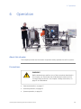
Operation ..............................................................................................................
123
6.1
6.2
Perform the run .....................................................................................................................................
Procedures after usage .....................................................................................................................
125
128
Maintenance .........................................................................................................
129
7.1
7.2
7.3
7.4
7.5
User maintenance schedule ...........................................................................................................
Cleaning ....................................................................................................................................................
Storage ......................................................................................................................................................
Disassembly and assembly .............................................................................................................
pH calibration .........................................................................................................................................
131
133
136
138
140
8
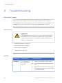
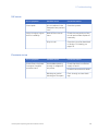
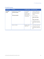
Troubleshooting ...................................................................................................
142
9
Reference information ........................................................................................
149
9.1
9.2
9.3
9.4
Specifications .........................................................................................................................................
Process wetted materials .................................................................................................................
Chemical resistance ............................................................................................................................
More information ..................................................................................................................................
150
156
157
159
Index .......................................................................................................................
160
6
7
4
UniFlux System Operating Instructions 28-9617-49 AC
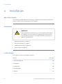
1 Introduction
1
Introduction
Scope of this document
This manual is valid for all variants of standard UniFlux systems. Your system is
CE-classified and the system configuration for your system is described in the General
Specification and on the system label.
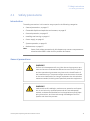
Prerequisites
In order to operate UniFlux System safely and according to the intended use the following
prerequisites must be met:
•
You should be acquainted with the use of general bioprocessing equipment and with
handling of biological materials.
•
UniFlux System must be installed according to the instructions in the Installation
chapter of this manual.
About this chapter
This chapter contains important user information, description of safety notices, regulatory
information, a general description of UniFlux System and its intended use, and a list of
associated documentation.
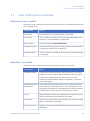
In this chapter
This chapter contains the following sections:
Section
See page
1.1 Important user information
6
1.2 Regulatory information
8
1.3 Associated documentation
UniFlux System Operating Instructions 28-9617-49 AC
11
5
1 Introduction
1.1 Important user information
1.1
Important user information
Read this before using UniFlux
System
All users must read the Safety chapter of the Operating Instructions before installing,
using or maintaining UniFlux System.
Do not operate UniFlux System in any other way than described in the user
documentation. If you do, you may be exposed to hazards that can lead to personal injury,
and you may cause damage to the equipment.
Intended use of UniFlux System
UniFlux systems are intended for pilot through production scale biological separations.
The systems are configured to operate hollow fiber cartridges suited for microfiltration
applications such as cell clarification/harvesting, or cassettes/hollow fibers for ultrafiltration applications, such as protein concentration and diafiltration in downstream unit
operations.
UniFlux is not suitable for operation in a potentially explosive atmosphere or for handling
flammable liquids.
UniFlux System shall not be used in any clinical procedures, or for diagnostic purposes.
WARNING
Do not operate UniFlux System in any other way than described in
the Operating Instructions.
6
UniFlux System Operating Instructions 28-9617-49 AC
1 Introduction
1.1 Important user information
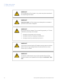
Safety notices
This user documentation contains WARNINGS, CAUTIONS and NOTICES concerning the
safe use of the product. See definitions below.
Warnings
WARNING
WARNING indicates a hazardous situation which, if not avoided,
could result in death or serious injury. It is important not to proceed
until all stated conditions are met and clearly understood.
Cautions
CAUTION
CAUTION indicates a hazardous situation which, if not avoided,
could result in minor or moderate injury. It is important not to
proceed until all stated conditions are met and clearly understood.
Notices
NOTICE
NOTICE indicates instructions that must be followed to avoid
damage to the product or other equipment.
Notes and tips
Note:
A note is used to indicate information that is important for trouble-free and
optimal use of the product.
Tip:
A tip contains useful information that can improve or optimize your procedures.
Typographical conventions
Software items are identified in the text by bold italic text. A colon separates menu levels,
thus File:Open refers to the Open command in the File menu.
Hardware items are identified in the text by bold text (e.g., Power switch).
UniFlux System Operating Instructions 28-9617-49 AC
7
1 Introduction
1.2 Regulatory information
1.2
Regulatory information
This section lists the directives and standards that are fulfilled by UniFlux System.
Manufacturing information
Requirement
Content
Name and address of manufacturer
GE Healthcare Bio-Sciences AB,
Björkgatan 30, SE 751 84 Uppsala
Sweden
Place and date of declaration
See EC Declaration of Conformity
Identity of person authorized to sign DoC
See EC Declaration of Conformity
International standards
The following standards have been applied:
Standard
Description
Notes
IEC/EN 61010-1
Safety requirements for electrical
equipment for measurement, control, and
laboratory use
EN 61326-1
EMC emissions and immunity
requirements for electrical equipment for
measurement, control and laboratory
use. Emission according to CISPR 11,
Group 1, class A
Harmonized with
2004/108/EC
EN-ISO 12100
Safety of machinery - General principles
for design - Risk assessment and risk
reduction
Harmonized with
2006/42/EC
Additional regulatory compliance
In addition, this product fulfils the following requirements:
8
Standard
Description
Notes
ASME-BPE
All steel piping welds, including contact
welds
UniFlux System Operating Instructions 28-9617-49 AC
1 Introduction
1.2 Regulatory information
Standard
Description
USP class VI, EN
10204 2.1
Traceability for process wetted and
pressure retaining polymers and
elastomers
EN 287:1, 1418, EN
ISO 15607,
15609-1, 15614-1,
5817, 6520,
3834-2
Welding
Notes
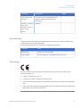
CE Conformity
This product complies with the European directives listed in the table, by fulfilling the
corresponding harmonized standards.
A copy of the Declaration of Conformity is available on request.
Directive
Title
2006/42/EC
Machinery Directive (MD)
2004/108/EC
Electromagnetic Compatibility (EMC) Directive
CE Marking
The CE marking and the corresponding Declaration of conformity is valid for the
instrument when it is:
•
used as a stand-alone unit, or
•
connected to other CE marked instruments, or
•
connected to other products recommended or described in the user documentation,
and
•
used in the same state as it was delivered from GE Healthcare, except for alterations
described in the user documentation.
UniFlux System Operating Instructions 28-9617-49 AC
9
1 Introduction
1.2 Regulatory information
Regulatory compliance of
connected equipment
Any equipment connected to the UniFlux System should meet the safety requirements
of EN 61010-1/IEC 61010-1, or relevant harmonized standards. Within EU, connected
equipment must be CE marked.
10
UniFlux System Operating Instructions 28-9617-49 AC
1 Introduction
1.3 Associated documentation
1.3
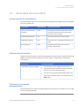
Associated documentation
System specific documentation
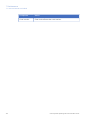
The most important documents in the document package with regard to technical aspects
of UniFlux System are:
Document
Abbreviation
Purpose/Contents
Piping and Instrument
Diagram
P&ID
Schematic overview of the entire process
flow, all components and instruments
and the control system.
General Specification
GS
Technical data for UniFlux System.
Assembly Drawing
AD
Physical layout. Provides all dimensional
data.
Bill of Material
BOM
Detailed specifications for process
related components.
Software documentation
Together with each system, the following software documentation is supplied providing
additional information that applies to UniFlux System, independent of the specific
configuration:
Document
Purpose/Contents
UNICORN™ manual package
•
The manuals contain detailed instructions on
how to administer UNICORN, work with methods,
perform runs and evaluate results.
•
The Online help contains dialog descriptions for
UNICORN. The Online help is accessed from the
Help menu.
Third-party component
documentation
Documentation for components produced by a third-party are, if existent, also included
in the document package.
UniFlux System Operating Instructions 28-9617-49 AC
11
2 Safety instructions
2
Safety instructions
About this chapter
This chapter describes safety precautions and emergency shutdown procedures for
UniFlux. The labels on the system and information regarding recycling are also described.
Important
WARNING
Before installing, operating or maintaining UniFlux System, all
users must read and understand the entire contents of this
chapter to become aware of the hazards involved.
Failure to do this may cause human injury or death, or damage to
the equipment.
In this chapter
This chapter contains the following sections:
Section
12
See page
2.1 Safety precautions
13
2.2 Labels
24
2.3 Emergency procedures
32
2.4 Recycling information
36
2.5 Declaration of Hazardous Substances (DoHS)
37
UniFlux System Operating Instructions 28-9617-49 AC
2 Safety instructions
2.1 Safety precautions
2.1
Safety precautions
Introduction
The safety precautions in this section are grouped in the following categories:
•
General precautions, on page 13
•
Flammable liquids and explosive environment, on page 15
•
Personal protection, on page 15
•
Installing and moving, on page 16
•
Power supply, on page 19
•
System operation, on page 20
•
Maintenance, on page 22
Note:
Some of the safety precautions in this chapter may concern components or
situations described in other UniFlux product documents.
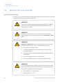
General precautions
WARNING
Perform a risk assessment for any risks due to the process or process environment. Evaluate the effects the use of UniFlux System
and the operational processes may have on the classification of
the hazardous area. The process might cause the area to increase
or the zone classification to change. Implement the risk reduction
measures needed, including use of personal protection equipment.
WARNING
Make sure that all installation, maintenance, operation and inspection is carried out by qualified personnel who are adequately
trained, understand and adhere to local regulations and the operating instructions, and have a thorough knowledge of UniFlux
System and the entire process.
UniFlux System Operating Instructions 28-9617-49 AC
13
2 Safety instructions
2.1 Safety precautions
WARNING
Do not operate UniFlux System in any other way than described in
the Operating Instructions.
WARNING
Protective earth. UniFlux System must always be connected to
protective earth when energized.
WARNING
Do not use UniFlux System if it is not working properly, or if it has
suffered any damage, for example:
•
damage to the power cord or its plug
•
damage caused by dropping the equipment
•
damage caused by splashing liquid onto it
WARNING
Only personnel authorized by GE Healthcare may open the cabinet
doors. There is high voltage inside the cabinet that can cause
human injury or death.
WARNING
The electric cabinet doors may only be opened when UniFlux
System is taken out of operation and subject to LOCK OUT / TAG
OUT.
14
UniFlux System Operating Instructions 28-9617-49 AC
2 Safety instructions
2.1 Safety precautions
Flammable liquids and explosive
environment
WARNING
Flammable liquids. UniFlux System is not approved to handle
flammable liquids.
WARNING
Explosive environment. UniFlux System is not approved for work
in a potentially explosive atmosphere, in areas classified as Zone
0 to Zone 2 according to IEC 60079-10 2002. UniFlux System does
not fulfill the requirements of the ATEX Directive.
Personal protection
WARNING
When using hazardous chemicals and biological agents, take all
suitable protective measures, such as wearing protective glasses
and gloves resistant to the substances used. Follow local and/or
national regulations for safe operation and maintenance of UniFlux.
WARNING
Personal Protective Equipment (PPE). Whenever packing, unpacking, transporting or moving the system, wear protective foot wear,
preferably with steel lining.
WARNING
High pressure. UniFlux System operates under high pressure. Wear
protective glasses and other required Personal Protective Equipment (PPE) at all times.
UniFlux System Operating Instructions 28-9617-49 AC
15
2 Safety instructions
2.1 Safety precautions
CAUTION
Do not insert your fingers or other objects into fans or other moving
parts.
CAUTION
Do not touch the system while pumping fluid through the system
that has a temperature above the normal working temperature.
Do not touch the system until you are sure that this can be done
without risk and when all components in the system have reached
the normal working temperature range.
CAUTION
Use ear protection whenever working close to the system in operation.
Installing and moving
WARNING
UniFlux must be installed and prepared by GE Healthcare personnel
or third party authorized by GE Healthcare.
WARNING
To prevent bacterial growth, UniFlux System may be partly filled
with denatured Ethanol (18% C2H5OH (Ethanol), 2% C3H7OH (Isopropanol) and 80% H2O (water)) or 0.1 M NaOH (Sodium Hydroxide)
at delivery.
Flush out the denatured Ethanol or Sodium Hydroxide before assembling, testing or integrating UniFlux into the intended process
context.
16
UniFlux System Operating Instructions 28-9617-49 AC
2 Safety instructions
2.1 Safety precautions
WARNING
Move transport crates. Make sure that the forklift has capacity to
safely lift the crate weight. Make sure that the crate is properly
balanced so that it will not accidentally tip when moved.
WARNING
Heavy object. Because of the significant weight of UniFlux System,
great care must be taken not to cause squeezing or crushing injuries during movement. At least two, but preferably three or more,
persons are recommended when moving the unit.
WARNING
Access to power switch and power cord. The power switch must
always be easy to access. The power cord must always be easy to
disconnect.
WARNING
The UniFlux shall only be lifted using the lower part of the skid. The
UniFlux is not fitted with lifting eye bolts or other devices for hoist
lift.
CAUTION
The wheels of UniFlux should be locked during normal use. The
wheels should be unlocked only when moving the unit.
CAUTION
Make sure that all tubing, hoses and cables are placed so that the
risk for tripping accidents is minimized.
CAUTION
UniFlux System is designed for indoor use only.
UniFlux System Operating Instructions 28-9617-49 AC
17
2 Safety instructions
2.1 Safety precautions
CAUTION
Do not use UniFlux System in a dusty atmosphere or close to
spraying water.
CAUTION
Make sure that correct air pressure is always maintained. Too high
or too low air pressure may be hazardous and may cause erroneous
results and leakage.
CAUTION
Before moving the UniFlux System the following must be done:
1
Empty the UniFlux.
2
Shut down the UniFlux and disconnect the power cord.
3
Disconnect the air supply lines.
4
Disconnect all process lines.
CAUTION
Make sure that the common waste outlet is:
•
Never exposed to back-pressure.
•
Connected to piping with at least the same diameter as the
common waste outlet piping.
•
Connected to piping that allows maximum waste flow to be
transported away from UniFlux System without pooling.
CAUTION
Make sure that the console arm is firmly positioned with the top
part of the handle fully inserted, so that the bushing is able to absorb the weight of the console when the console arm is fully extended. The console may fall and cause damage and/or injury if the
console arm is not properly positioned.
18
UniFlux System Operating Instructions 28-9617-49 AC
2 Safety instructions
2.1 Safety precautions
CAUTION
When handling the operator console, make sure that no body parts
are caught between the sections of the console arm.
NOTICE
Any computer used with the equipment shall comply with IEC 60950
and be installed and used according to the manufacturer's instructions.
Power supply
WARNING
Protective ground. UniFlux System must always be connected to
a grounded power outlet.
WARNING
National Codes and standards (NEC, VDE, BSI, IEC, UL etc.) and local
codes outline provisions for safely installing electrical equipment.
Installation must comply with specifications regarding wire types,
conductor sizes, plug, branch circuit protection and disconnect
devices. Failure to do so may result in personal injury and/or
equipment damage.
WARNING
All electrical installations must be performed by authorized
personnel only.
UniFlux System Operating Instructions 28-9617-49 AC
19
2 Safety instructions
2.1 Safety precautions
System operation
WARNING
Safe distance. Always maintain a safe distance from
UniFlux during drainage or other activities that may involve
splashing.
WARNING
During operation, all doors must always be closed and locked.
WARNING
Before operation, all process connections and the piping system
must be tested for leakage at maximum pressure for continued
protection against injury risks due to fluid jets, burst pipes or potentially explosive atmosphere.
WARNING
Operating limits. Never exceed the operating limits stated in this
document and on the system label. Operation of UniFlux outside
these limits may damage equipment and bodily harm or death
may occur.
WARNING
Power failure. During a power failure, or if the EMERGENCY STOP
button is pressed, UniFlux may remain pressurized. Opening a line
or vessel at this point could result in the release of potentially hazardous process or cleaning fluid, and cause bodily harm.
When recovering from a power failure or emergency shutdown,
make sure all lines and vessels are depressurized before opening.
WARNING
Shutdown does not automatically result in depressurizing of the
piping system.
20
UniFlux System Operating Instructions 28-9617-49 AC
2 Safety instructions
2.1 Safety precautions
WARNING
Emergency stop. Pressing the EMERGENCY STOP will not shut off
mains power to the cabinet.
WARNING
Alarm signals. All alarm signals must be set within the limits
specified in the system documentation. Pressure and temperature
control must be activated while the system is in use to prevent the
piping system to leak or break.
WARNING
Alarms signals. Make sure to change back to the original alarm
level after UNICORN alarm buzzer test.
CAUTION
If an external Uninterruptible Power Supply (UPS) is used, this unit
must be powered before any other equipment.
CAUTION
To safely operate UniFlux System, knowledge of how to use
UNICORN is required. Refer to UNICORN user documentation as
required.
CAUTION
When handling the operator console, make sure that no body parts
are caught between the sections of the console arm.
CAUTION
Do not insert your fingers or other objects into fans or other moving
parts.
UniFlux System Operating Instructions 28-9617-49 AC
21
2 Safety instructions
2.1 Safety precautions
Maintenance
WARNING
LOCK OUT / TAG OUT! Before any maintenance or decommissioning work is performed on UniFlux System, make sure that:
•
it is empty and depressurized.
•
it is disconnected from process feed, electrical power and
pneumatic supply.
•
it is prevented from accidentally becoming re-energized during
maintenance.
•
it is clearly tagged as taken out of operation.
•
all process wetted areas are clean and decontaminated.
WARNING
Only personnel authorized by GE Healthcare may perform service,
installation, and maintenance of components inside the UniFlux
cabinet.
WARNING
Only spare parts and accessories that are approved or supplied
by GE Healthcare may be used for maintaining or servicing UniFlux.
WARNING
For continued protection against injury risks due to fluid jets, burst
pipes or potentially explosive atmosphere, the piping system must
be tested for leakage at maximum pressure:
22
•
After assembly or maintenance
•
Before operation or CIP
UniFlux System Operating Instructions 28-9617-49 AC
2 Safety instructions
2.1 Safety precautions
CAUTION
Do not climb on any parts of UniFlux except where clearly allowed.
Follow local regulations and make sure that equipment is properly
secured when inspecting UniFlux at high level.
UniFlux System Operating Instructions 28-9617-49 AC
23
2 Safety instructions
2.2 Labels
2.2
Labels
Introduction
This section describes the various labels on UniFlux and their meaning.
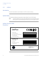
System labels
The illustrations below show examples of system labels for the UniFlux System.
Note:
The specific data shown on the system labels below are only examples. Actual
data is specific for each individual system and may vary from system to system.
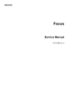
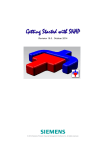
UniFlux 10 system label
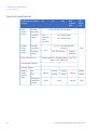
illustration
UniFlux
20
N3732
Serial number:
Year of manufacture:
Max system pressure/temperature:
4.14 bar g @ 2-30°C
Pneumatic supply:
6-10 bar
Overall protection class:
IP 55
UniFlux 10
Supply voltage:
230/110 V~
Frequency:
50/60 Hz
Max power consumption:
600 VA
Protection class:
IP 55
GE Healthcare Bio-Sciences AB
Björkgatan 30
S - 751 84 UPPSALA
Sweden
24
UniFlux System Operating Instructions 28-9617-49 AC
2 Safety instructions
2.2 Labels
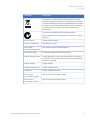
UniFlux 10 system label
description
Label text
Description
The system complies with applicable European directives.
This symbol indicates that the product contains hazardous
materials in excess of the limits established by the Chinese
standard SJ/T11363-2006 Requirements for Concentration
Limits for Certain Hazardous Substances in Electronics.
This symbol indicates that the waste of electrical and
electronic equipment must not be disposed as unsorted
municipal waste and must be collected separately. Please
contact an authorized representative of the manufacturer
for information concerning the decommissioning of
equipment.
The system complies with the requirements for
electromagnetic compliance (EMC) in Australia and New
Zealand.
Serial number
System serial number.
Year of manufacture
Manufacturing year.
Max system
pressure/temperature
Max system pressure at temperature.
Pneumatic supply
Pneumatic supply pressure requirement.
Overall protection class
Overall protection class, ingress protection according to
IEC 60529. This cover all components of the system except
the electric cabinet.
Supply voltage
Supply voltage.
Frequency
Supply voltage frequency.
Max power
consumption
Max power consumption.
Protection class
Protection class, ingress protection according to IEC 60529.
This covers the electric cabinet only.
UniFlux System Operating Instructions 28-9617-49 AC
25
2 Safety instructions
2.2 Labels
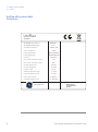
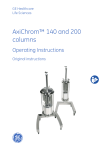
UniFlux 30 and 120 system label
illustration
UniFlux 120
20
N3732
Serial number:
Year of manufacture:
Max system pressure/temperature:
4.14 bar g @ 2-30°C
Pneumatic supply:
6-10 bar
Overall protection class:
IP 55
Supply voltage:
110/230 VAC
Supply voltage motor:
400/480 VAC
Frequency:
50/60 Hz
Max current consumption system:
3A
Max current consumption motor:
5A
GE Healthcare Bio-Sciences AB
Björkgatan 30
S - 751 84 UPPSALA
Sweden
UniFlux 30 and 120 system label
description
Label text
Description
The system complies with applicable European directives.
This symbol indicates that the product contains hazardous
materials in excess of the limits established by the Chinese
standard SJ/T11363-2006 Requirements for Concentration
Limits for Certain Hazardous Substances in Electronics.
26
UniFlux System Operating Instructions 28-9617-49 AC
2 Safety instructions
2.2 Labels
Label text
Description
This symbol indicates that the waste of electrical and
electronic equipment must not be disposed as unsorted
municipal waste and must be collected separately. Please
contact an authorized representative of the manufacturer
for information concerning the decommissioning of
equipment.
The system complies with the requirements for
electromagnetic compliance (EMC) in Australia and New
Zealand.
Serial number
System serial number.
Year of manufacture
Manufacturing year.
Max system
pressure/temperature
Max system pressure at temperature.
Pneumatic supply
Pneumatic supply pressure requirement.
Overall protection class
Overall protection class, ingress protection according to
IEC 60529. This cover all components of the system except
the electric cabinet.
Supply voltage
Supply voltage.
Supply voltage motor
Supply voltage motor.
Frequency
Supply voltage frequency.
Max current
consumption system
Max current consumption system.
Max current
consumption motor
Max current consumption motor.
UniFlux System Operating Instructions 28-9617-49 AC
27
2 Safety instructions
2.2 Labels
UniFlux 400 system label
illustration
UniFlux
TM
System
GE Healthcare Code no.
GE Healthcare Serial no.
GE Healthcare Model no.
2777
UniFlux 400
Year of manufacture
2011
Power supply system
1ph110/230VAC
Power supply pump
3ph400/480VAC
50/60 Hz
Frequency
Max current consumption system
5A
Max current consumption pump
18 A
Min fuse rating system
10 A SB
Min fuse rating pump
30 A SB
IP 55
Protection class
Ambient temperature range
Process temperature range
2 - 30°C
2 - 60°C
Max process pressure
4.15 bar g
Pneumatic supply min-max
6 - 10 bar g
GE Healthcare
28
28982307
GE Healthcare
Björkgatan 30
751 84 UPPSALA
Sweden
UniFlux System Operating Instructions 28-9617-49 AC
2 Safety instructions
2.2 Labels
UniFlux 400 system label
description
Label text
Description
The system complies with applicable European directives.
This symbol indicates that the waste of electrical and
electronic equipment must not be disposed as unsorted
municipal waste and must be collected separately. Please
contact an authorized representative of the manufacturer
for information concerning the decommissioning of
equipment.
GE Healthcare Code no.
GE Healthcare Code no.
GE Healthcare Serial
no.
GE Healthcare Serial no.
GE Healthcare Model
no.
GE Healthcare Model no.
Year of manufacture
Year of manufacture.
Power supply system
Power supply system.
Power supply pump
Power supply pump.
Frequency
Supply voltage frequency.
Max current consumption system
Max current consumption system.
Max current consumption pump
Max current consumption pump.
Min fuse rating system
Min fuse rating system.
Min fuse rating pump
Min fuse rating pump.
Protection class
Protection class, ingress protection according to IEC 60529.
This covers the electric cabinet only.
Ambient temperature
range
Ambient temperature range.
Process temperature
range
Process temperature range.
Max process pressure
Max process pressure.
UniFlux System Operating Instructions 28-9617-49 AC
29
2 Safety instructions
2.2 Labels
Label text
Description
Pneumatic supply minmax
Pneumatic supply min-max.
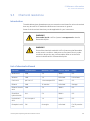
Safety labels
The table below describes the various safety labels that may be found on UniFlux.
Symbol/text
Description
Warning! Read the user documentation before using
the system. Do not open any covers or replace parts
unless specifically stated in the user documentation.
Warning! High Voltage. Always make sure that the
system is disconnected from electric power before
opening the cabinet doors or disconnecting any electric
device.
WARNING! Max operating pressure as stated on the
label.
EMERGENCY STOP label, yellow with black text.
(emergency stop button is red).
Refer to Section 2.3 Emergency procedures, on page 32
for further information regarding the emergency stop.
WARNING!
High voltage inside cabinet!
Authorised personnel only!
For continued protection
against fire replace only with
same type and rating of fuse
WARNING! High voltage inside cabinet! Authorized
personnel only! For continued protection against fire,
only replace fuses with the same type and rating.
IMPORTANT! Before service/maintenance or return to
GE Healthcare, clean the equipment and accompany it
with a decontamination statement, specifying
substances with which it has been in contact during
use and the method of cleaning.
30
UniFlux System Operating Instructions 28-9617-49 AC
2 Safety instructions
2.2 Labels
Symbol/text
CAUTION!
Description
CAUTION! Pressure control valve shall be set to 5.5 –
7 bar g for instrument air supply.
Pressure control valve
shall be set to
5.5 – 7 bar g
for instrument air
supply
Warning! Before connecting the system, make sure that
the system setting corresponds with the power supply.
Disconnect switch and branch circuit to be provided by
installer.
NOTE!
Different power supply cables in CE/UL systems
CE
UL
P
1
Brown
N
2
White
Protective earth
Yellow/green
Green
Use ear protection whenever working close to the system in operation.
Hot surface. Risk of burning injuries.
UniFlux System Operating Instructions 28-9617-49 AC
31
2 Safety instructions
2.3 Emergency procedures
2.3
Emergency procedures
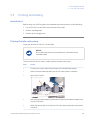
Introduction
This section describes how to do an emergency shutdown of UniFlux System, and the
result in the event of power failure.
Precautions
WARNING
Emergency stop. Pressing the EMERGENCY STOP will not shut off
mains power to the cabinet.
WARNING
Power failure. During a power failure, or if the EMERGENCY STOP
button is pressed, UniFlux may remain pressurized. Opening a line
or vessel at this point could result in the release of potentially hazardous process or cleaning fluid, and cause bodily harm.
When recovering from a power failure or emergency shutdown,
make sure all lines and vessels are depressurized before opening.
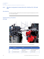
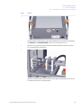
Emergency stop button and main
power switch
UniFlux 10
32
UniFlux System Operating Instructions 28-9617-49 AC
2 Safety instructions
2.3 Emergency procedures
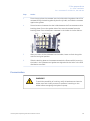
UniFlux 30 and 120
B
A
UniFlux 400
B
A
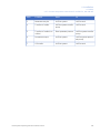
Part
Function
A
EMERGENCY STOP button
B
MAIN SWITCH, power
UniFlux System Operating Instructions 28-9617-49 AC
33
2 Safety instructions
2.3 Emergency procedures
Emergency shutdown
Step
Action
Result
1
Press the EMERGENCY STOP
button (A).
•
All motors and externally moving
components stop immediately.
•
The built-in computer and other
components remain powered.
•
No data is lost.
2
If required, also switch off the •
mains power supply (B), disconnect the power cord or switch
off the fixed power supply cir- •
cuit breaker.
The entire system, including the
computer becomes powerless.
Data and run status may become lost.
Power failure
The system power is lost if the MAIN SWITCH on the cabinet is turned off, the mains
cable disconnected or the power supply is lost.
All pumps stop if the electrical power to the system is lost. All valves will immediately
revert to default positions. Any data that has not been saved at that time may be lost.
If only the system is affected by the power failure and not the computer, UNICORN will
display text saying that communication has been broken and that no data are recovered.
When power returns to normal, the system will be in End state (i.e., it will not resume the
run).
Restart after emergency shut
down or power failure
Follow the instruction below to restart UniFlux after emergency shut down or power
failure.
34
Step
Action
1
Make sure that the condition that caused the power failure or emergency
stop is corrected.
UniFlux System Operating Instructions 28-9617-49 AC
2 Safety instructions
2.3 Emergency procedures
Step
Action
2
Reset the EMERGENCY STOP button by twisting it clock-wise.
3
Press the CONTINUE button in UNICORN.
UniFlux System Operating Instructions 28-9617-49 AC
35
2 Safety instructions
2.4 Recycling information
2.4
Recycling information
Introduction
This section contains information about the decommissioning of UniFlux System.
Decontamination
UniFlux System shall be decontaminated before decommissioning and all local regulations
shall be followed with regard to scrapping of the equipment.
Disposal, general instructions
When taking UniFlux System out of service, the different materials must be separated
and recycled according to national and local environmental regulations.
Recycling of hazardous
substances
UniFlux System contains hazardous substances. Detailed information is available from
your GE Healthcare representative.
Disposal of electrical
components
Waste electrical and electronic equipment must not be disposed as unsorted municipal
waste and must be collected separately. Please contact an authorized representative
of the manufacturer for information concerning the decommissioning of equipment.
36
UniFlux System Operating Instructions 28-9617-49 AC
2 Safety instructions
2.5 Declaration of Hazardous Substances (DoHS)
2.5
Declaration of Hazardous Substances (DoHS)
Introduction
The following product pollution control information is provided according to SJ/T113642006 Marking for Control of Pollution caused by Electronic Information Products.
根据SJ/T11364-2006《电子信息产品污染控制标识要求》特提供如下有关污染 控制
方面的信息
Symbols used in pollution control
label
电子信息产品污染控制标志说明
Label
Meaning
This symbol indicates the product contains hazardous materials in excess of the limits established by the Chinese standard SJ/T11363-2006
Requirements for Concentration Limits for Certain Hazardous Substances in Electronic Information Products. The number in the symbol
is the Environment-friendly Use Period (EFUP), which indicates the period
during which the toxic or hazardous substances or elements contained
in electronic information products will not leak or mutate under normal
operating conditions so that the use of such electronic information
products will not result in any severe environmental pollution, any
bodily injury or damage to any assets. The unit of the period is “Year”.
In order to maintain the declared EFUP, the product shall be operated
normally according to the instructions and environmental conditions
as defined in the product manual, and periodic maintenance schedules
specified in Product Maintenance Procedures shall be followed strictly.
Consumables or certain parts may have their own label with an EFUP
value less than the product. Periodic replacement of those consumables
or parts to maintain the declared EFUP shall be done in accordance
with the Product Maintenance Procedures.
This product must not be disposed of as unsorted municipal waste,
and must be collected separately and handled properly after decommissioning.
UniFlux System Operating Instructions 28-9617-49 AC
37
2 Safety instructions
2.5 Declaration of Hazardous Substances (DoHS)
Label
Meaning
该标志表明本产品含有超过SJ/T11363-2006《电子信息产品中有毒
有害物质的限 量要求》中限量的有毒有害物质。标志中的数字为本
产品的环保使用期,表明本 产品在正常使用的条件下,有毒有害物
质不会发生外泄或突变,用户使用本产品 不会对环境造成严重污染
或对其人身、财产造成严重损害的期限。单位为年。
为保证所申明的环保使用期限,应按产品手册中所规定的环境条件
和方法进行正 常使用,并严格遵守产品维修手册中规定的期维修和
保养要求。
产品中的消耗件和某些零部件可能有其单独的环保使用期限标志,
并且其环保使 用期限有可能比整个产品本身的环保使用期限短。应
到期按产品维修程序更换那 些消耗件和零部件,以保证所申明的整
个产品的环保使用期限。
本产品在使用寿命结束时不可作为普通生活垃圾处理,应被单独收
集妥善处理
List of hazardous substances and
their concentrations
产品中有毒有害物质或元素的名称及含量
Indication for each major part if substance exceeds limit
Value
Meaning
O
Indicates that this toxic or hazardous substance contained in all of the
homogeneous materials for this part is below the limit requirement in
SJ/T11363-2006.
表示该有毒有害物质在该部件所有均质材料中的含量均在SJ/T113632006 标准规定的限量要 求以下
X
Indicates that this toxic or hazardous substance contained in at least
one of the homogeneous materials used for this part is above the limit
requirement in SJ/T11363-2006.
•
Data listed in the table represents best information available at the
time of publication
表示该有毒有害物质至少在该部件的某一均质材料中的含量超出
SJ/T11363-2006 标准规定的
限量要求
•
38
此表所列数据为发布时所能获得的最佳信息
UniFlux System Operating Instructions 28-9617-49 AC
2 Safety instructions
2.5 Declaration of Hazardous Substances (DoHS)
List of hazardous substances
Component
name
Hazardous substance
有毒有害物质或元素
部件名称
1
Pb
Hg
Cd
Cr6+
PBB
PBDE
铅
汞
镉
六价铬
多溴联苯
多溴二苯醚
UniFlux 10 1
X
O
O
O
O
O
UniFlux 30 1
X
O
O
O
O
O
UniFlux 120 1
X
O
O
O
O
O
UniFlux 400 1
X
O
O
O
O
O
The product has not been tested as per the Chinese standard SJ/T11363-2006 Requirements
for Concentration Limits for Certain Hazardous Substances in Electronic Information Product.
UniFlux System Operating Instructions 28-9617-49 AC
39
3 System description
3
System description
About this chapter
This chapter provides an overview of the technical properties of UniFlux.
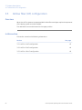
In this chapter
This chapter contains the following sections:
Section
40
See page
3.1 Overview
41
3.2 UniFlux systems layout
42
3.3 Automation
57
3.4 Cassette holders
59
3.5 Hollow fiber (HF) configuration
62
3.6 Flow charts
68
3.7 UNICORN control system
80
UniFlux System Operating Instructions 28-9617-49 AC
3 System description
3.1 Overview
3.1
Overview
General
These Operating Instructions cover the UniFlux 10, 30, 120 and 400 systems.
The UniFlux series is a line of cross flow filtration (CFF) systems that utilizes UNICORN
software for full automation with data logging capabilities over the entire cross flow
process.
UniFlux systems are intended for pilot through production scale biological separations.
The systems are configured to operate hollow fiber cartridges suited for microfiltration
applications such as cell clarification/harvesting, or cassettes/hollow fibers for ultrafiltration applications, such as protein concentration and diafiltration in downstream unit
operations.
Material compliance
All plastic and polymer materials that come in contact with buffers and samples are
compliant with USP Class VI.
Used materials are traceable back to their production batches.
You can find information about the design and materials used in your system in the
System Documentation.
Chemical resistance is described in Section 9.3 Chemical resistance, on page 157
A list of process wetted materials can be found in Section 9.2 Process wetted materials,
on page 156.
UniFlux System Operating Instructions 28-9617-49 AC
41
3 System description
3.2 UniFlux systems layout
3.2
UniFlux systems layout
In this section
This section contains the following subsections:
Section
42
See page
3.2.1 Illustrations of UniFlux 10 system
43
3.2.2 Illustrations of UniFlux 30 and 120 systems
48
3.2.3 Illustrations of UniFlux 400 system
52
UniFlux System Operating Instructions 28-9617-49 AC
3 System description
3.2 UniFlux systems layout
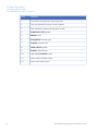
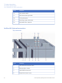
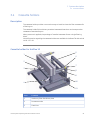
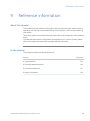
3.2.1 Illustrations of UniFlux 10 system
3.2.1
Illustrations of UniFlux 10 system
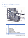
UniFlux 10: Front view
UniFlux System Operating Instructions 28-9617-49 AC
43
3 System description
3.2 UniFlux systems layout
3.2.1 Illustrations of UniFlux 10 system
44
Part
Function
1
Permeate line equipment mounting beam
2
Tank and peristaltic pumps mounting beam
3
Filter cassette, cassette configuration shown
4
EMERGENCY STOP button
5
PAUSE button
6
RUN/PAUSE indicator light
7
POWER indicator light
8
MAIN SWITCH, power
9
ALARM indictaor light
10
UNICORN CONTINUE button
11
Caster without brake (2 pcs)
12
Caster with brake (2 pcs)
UniFlux System Operating Instructions 28-9617-49 AC
3 System description
3.2 UniFlux systems layout
3.2.1 Illustrations of UniFlux 10 system
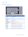
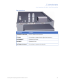
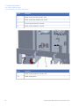
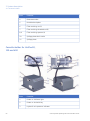
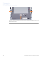
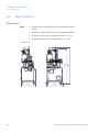
UniFlux 10: Rear view
Part
Function
10
Electric cabinet door locks (2)
11
Filter and fan for cabinet cooling
12
External device connectors
UniFlux System Operating Instructions 28-9617-49 AC
45
3 System description
3.2 UniFlux systems layout
3.2.1 Illustrations of UniFlux 10 system
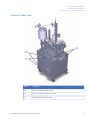
UniFlux 10: External connectors
Connectors in front recess
46
Part
Function
M-241
Mixer motor control
AIT-131
UV-connector
EXTERNAL SIGNALS
Connector for user process site signal communications
PROFIBUS
Profibus connector
AIR INLET
System air inlet
UNICORN ETHERNET
UNICORN Ethernet connector
AIR EXHAUST
System air exhaust
ZSO-064
Hollow fiber drain valve control signal connector
ZSO-081
Quadruple valve option control signal connector
ZSO-082
Quadruple valve option control signal connector
ZSO-083
Quadruple valve option control signal connector
ZSO-084
Quadruple valve option control signal connector
UniFlux System Operating Instructions 28-9617-49 AC
3 System description
3.2 UniFlux systems layout
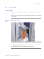
3.2.1 Illustrations of UniFlux 10 system
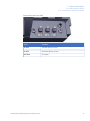
Connectors on rear side
Part
Function
P-202
Transfer pump control
P-203
Permeate pump control
AIT-131
UV-signal
UniFlux System Operating Instructions 28-9617-49 AC
47
3 System description
3.2 UniFlux systems layout
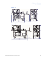
3.2.2 Illustrations of UniFlux 30 and 120 systems
3.2.2
Illustrations of UniFlux 30 and 120 systems
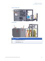
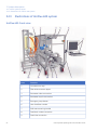
UniFlux 30: Front view
The illustration shows UniFlux 30, but also applies to UniFlux 120.
48
Part
Function
1
Mounting plates for peristaltic pumps
2
CIP-media outlet
3
Swivelling caster with brake (4 pcs)
4
Filter cassette holder
5
Emergency stop button
6
User interface console
7
Skid maneouvering handles
8
Hydraulic manouvering unit for filter cassette holder
9
Adjustable floor supports
UniFlux System Operating Instructions 28-9617-49 AC
3 System description
3.2 UniFlux systems layout
3.2.2 Illustrations of UniFlux 30 and 120 systems
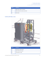
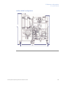
UniFlux 30: Rear view
The illustration shows UniFlux 30, but also applies to UniFlux 120.
Part
Function
10
Connectors on top
11
Electric cabinet
12
Permeate outlet connection
13
Permeate recycle connection
14
UNICORN status lights
15
Main power switch
16
System label
17
Retentate outlet (cassette configuration)
18
Electrical connectors
UniFlux System Operating Instructions 28-9617-49 AC
49
3 System description
3.2 UniFlux systems layout
3.2.2 Illustrations of UniFlux 30 and 120 systems
Part
Function
19
Feed inlet connection
20
Feed drain outlet connection
UniFlux 30 and 120: External
connectors
Rear wall connectors
50
Connector
Function
POWER SUPPLY TANK
Connection to UniFlux tank if provided
P-202
Connection to transfer pump option
P-203
Connection to permeate pump option
PROFIBUS
Connection to UniFlux tank Profibus control (or other controlled external equipment)
CAN BUS TANK
Connection to UniFlux tank CAN-bus control
UniFlux System Operating Instructions 28-9617-49 AC
3 System description
3.2 UniFlux systems layout
3.2.2 Illustrations of UniFlux 30 and 120 systems
Top connectors
Connector
Function
UNICORN ETHERNET
Unicorn Ethernet connection
LTS-166
Connection to external tank digital level sensors
AIR EXHAUST
System air exhaust
AIR INLET
System air inlet
EXTERNAL SIGNALS
Connection to process site signals
UniFlux System Operating Instructions 28-9617-49 AC
51
3 System description
3.2 UniFlux systems layout
3.2.3 Illustrations of UniFlux 400 system
3.2.3
Illustrations of UniFlux 400 system
UniFlux 400: Front view
52
Part
Function
1
Connectors on top
2
Filter skid connector pipes
3
Permeate outlet connection
4
Permeate recycle connection
5
Emergency stop button
6
User interface console
7
Skid maneouvering handle
8
Feed drain outlet connection
9
Feed inlet connection
UniFlux System Operating Instructions 28-9617-49 AC
3 System description
3.2 UniFlux systems layout
3.2.3 Illustrations of UniFlux 400 system
Part
Function
10
Retentate outlet connection
11
Retentate drain outlet connection
12
Filter drain
UniFlux 400: Rear view
Part
Function
13
Emergency stop button
14
UNICORN status lights
15
Connectors on top
UniFlux System Operating Instructions 28-9617-49 AC
53
3 System description
3.2 UniFlux systems layout
3.2.3 Illustrations of UniFlux 400 system
Part
Function
16
Main power switch
17
Skid maneouvering handle
18
CIP-media outlet
19
Swivelling caster with brake
20
Adjustable floor supports
UniFlux 400: External connectors
Top connectors
54
Part
Function
1
UPS power failure alarm input
2
Remote alarm output
3
UNICORN Ethernet port
4
Digital level sensor input
UniFlux System Operating Instructions 28-9617-49 AC
3 System description
3.2 UniFlux systems layout
3.2.3 Illustrations of UniFlux 400 system
Part
Function
5
Air exhaust
6
Air inlet
7
Optional I/O interface
8
Analog level sensor input
9
Main power supply
10
Power supply P-201
Inner wall connectors
Part
Function
1
Control signal ZSO-065
2
Pressure signal hydraulic unit system side
3
Pluto safe bus
4
Control signal P-202/P-203/tank
UniFlux System Operating Instructions 28-9617-49 AC
55
3 System description
3.2 UniFlux systems layout
3.2.3 Illustrations of UniFlux 400 system
56
Part
Function
5
Power supply transfer pump P-202
6
Power supply permeate pump P-203
7
Control signal operator console
8
Power supply operator console
Part
Function
9
Power supply hydraulic unit HC-291
10
Power supply tank
UniFlux System Operating Instructions 28-9617-49 AC
3 System description
3.3 Automation
3.3
Automation
Control system
The UniFlux System is fully automated by means of the UNICORN control system. Once
the required methods are created and approved, a non-expert user can safely operate
the system.
Refer to Section 3.7 UNICORN control system, on page 80 for information on the UNICORN
control system.
Computer for UniFlux 30, 120 and
400
The optional computer is built into the cabinet and fully protected from the outside environment. If the computer option is not ordered, stand-alone computers are used instead.
The computer automatically starts when the system power is turned on, no specific
starting procedure is required for the computer.
For computer specifications, refer to the system documentation kit.
UniFlux System Operating Instructions 28-9617-49 AC
57
3 System description
3.3 Automation
User console for UniFlux 30, 120
and 400
The display and input devices are ergonomically designed for use in a clean production
environment.
Communications
All communication with controlled components mounted outside the cabinet uses the
Profibus™ industry standard communication protocol and hardware.
58
UniFlux System Operating Instructions 28-9617-49 AC
3 System description
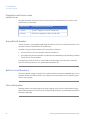
3.4 Cassette holders
3.4
Cassette holders
Description
The cassette holder provides a convenient way to install and use the filter cassettes for
a filtering run.
The cassette holder follow industry standard cassette dimensions and accepts other
cassettes of standard layout.
When pressure is applied, the package of installed cassettes forms a single filtering
block.
More information regarding the cassette holders are available in the Data File with article
no 18-1171-61.
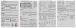
Cassette holder for UniFlux 10
5
1
6
2
7
3
8
9
10
4
11
Part
Function
1
Stationary filter distributor plate
2
Permeate outlet
3
Feed inlet
UniFlux System Operating Instructions 28-9617-49 AC
59
3 System description
3.4 Cassette holders
Part
Function
4
Retentate outlet
5
Movable back plate
6
Filter retaining nut (2)
7
Filter retaining threaded rod (2)
8, 9
Filter retaining spacers (4)
10
Spillage plate drain outlet
11
Spillage plate
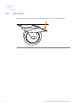
Cassette holder for UniFlux30,
120 and 400
60
Part
Function
1
Power on indicator light
2
Power on lock with key
3
Hydraulic unit pressure indicator
UniFlux System Operating Instructions 28-9617-49 AC
3 System description
3.4 Cassette holders
Part
Function
4
Hydraulic unit system label
5
Filter cassette holder permeate outlet
6
Filter cassette holder retentate outlet
7
Filter cassette holder feed inlet
8
Filter cassette spillage waste outlet
9
Hydraulic unit main power switch
10
Depressurize button
11
Pressurize button
12
Cassette holder distributor plate
13
Cassette holder upper guide pin (2 versions supplied for different types of
filter)
14
Cassette holder lower guide pin
15
Cassette holder movable pressurization plate
16
Cassette holder fixed pressurization plate
17
Hydraulic cylinder
18
Cassette holder bottom filter support
19
Filter cassette spillage collection plate
20
Hydraulic unit operation enabling button
21
Hydraulic unit spillage collection plate
UniFlux System Operating Instructions 28-9617-49 AC
61
3 System description
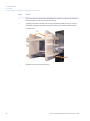
3.5 Hollow fiber (HF) configuration
3.5
Hollow fiber (HF) configuration
Overview
When the UniFlux systems are operated with hollow fiber cartridges, required components
of the piping system must be installed.
The retentate line must be located in the upper position.
In this section
This section contains the following subsections:
Section
62
See page
3.5.1 UniFlux 10 HF configuration
63
3.5.2 UniFlux 30 HF configuration
64
3.5.3 UniFlux 120 HF configuration
66
UniFlux System Operating Instructions 28-9617-49 AC
3 System description
3.5 Hollow fiber (HF) configuration
3.5.1 UniFlux 10 HF configuration
3.5.1
UniFlux 10 HF configuration
Illustration
Part
Function
1
Retentate hose
2
Permeate hose
3
Hollow fiber cartridge, size 5 or 6 is accepted.
4
HF cartridge drain valve (XV-064)
5
HF cartridge drain hose
UniFlux System Operating Instructions 28-9617-49 AC
63
3 System description
3.5 Hollow fiber (HF) configuration
3.5.2 UniFlux 30 HF configuration
3.5.2
UniFlux 30 HF configuration
Illustration: Hollow fiber size 75
2
3
6
1
2
3
5
6
An optional spool piece kit is needed to mount size 75 hollow fibers on the system.
64
UniFlux System Operating Instructions 28-9617-49 AC
3 System description
3.5 Hollow fiber (HF) configuration
3.5.2 UniFlux 30 HF configuration
Description of HF components
Part
Function
1
Retentate line, re-arranged to upper position for HF configuration
2
Hollow fiber cartridge
3
Permeate outlet hose
4
Feed line extension pipe
5
HF cartridge drain hose
6
HF cartridge drain valve (XV-065)
UniFlux System Operating Instructions 28-9617-49 AC
65
3 System description
3.5 Hollow fiber (HF) configuration
3.5.3 UniFlux 120 HF configuration
3.5.3
UniFlux 120 HF configuration
Illustration: Hollow fiber size 75
1
2
3
4
5
7
8
9
An optional spool piece kit is needed to mount size 75 hollow fibers on the system.
66
UniFlux System Operating Instructions 28-9617-49 AC
3 System description
3.5 Hollow fiber (HF) configuration
3.5.3 UniFlux 120 HF configuration
Description of HF components
Part
Function
1
Retentate line mounted in upper position
2
Retentate collector manifold
3
Hollow fiber cartridges (2)
4
Permeate hoses (2)
5
Permeate collector manifold
6
Feed extension pipes (2)
7
Permeate drain hoses (2)
8
Permeate drain collector manifold (2)
9
Permeate drain valve (XV-065)
UniFlux System Operating Instructions 28-9617-49 AC
67
3 System description
3.6 Flow charts
3.6
Flow charts
Overview
This section contains flow diagrams and component descriptions for the UniFlux System.
In this section
This section contains the following subsections:
Section
68
See page
3.6.1 UniFlux 10
69
3.6.2 UniFlux 30, 120 and 400
72
UniFlux System Operating Instructions 28-9617-49 AC
XV-084
XV-083
ME3
P-202
UniFlux System Operating Instructions 28-9617-49 AC
PT-111
P4
XV-061
XV-001
F P
FT-141
P-201
P3
PT-112
P
XV-052
T P
P6
UV pH
T
P F C
P5
XV-063
XV-064
FILTER
TE-161 PT-113
FA-231
CV-321
XV-051 PCV-341
T-342
F
PT-114
ME2
PSE-371
FA-232
P
FT-142
WE-176
TANK
B1
M-241
ME1 XV-041 PY-342
PS-342 FT-143
CE/TE-101
B5
B4
XV-082
XV-081
XV-031
P1
XV-032
P-203
P2
3.6.1
B3
B2
3 System description
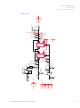
3.6 Flow charts
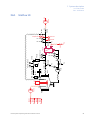
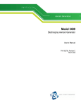
3.6.1 UniFlux 10
UniFlux 10
AE-121
AE-131
69
3 System description
3.6 Flow charts
3.6.1 UniFlux 10
Tag / System
Function
Note
AE-121
Permeate pH-meter
Option
AE-131
Permeate UV-meter
Option
B1
Tank feed inlet
B2, B3, B4
Quadruple inlets 1, 2 and 3
B5
Quadruple inlet 4
CE-101
Permeate conductivity meter with an integrated temperature meter (TE-101)
CV-321
Filter integrity test check valve
FA-231
Filter integrity test sanitary filter
FA-232
Tank vent sanitary filter
FILTER
Cross flow filter. Can be either hollow fibre
(HF) cartridge or filter cassette.
FT-141
Feed flow meter
FT-142
Permeate flow meter
FT-143
Filter integrity test flow meter
M-241
Feed tank agitator motor
ME1
Tank vent
ME2
Tank jacket connection
ME3
Tank jacket connection
P1
Permeate outlet
P2
Permeate pump outlet
P3
Retentate drain
P4
Feed drain / CIP outlet
P5
Permeate drain
P6
HF filter cartridge drain
P-201
Feed pump
70
Part of quadruple inlet option
Option
Not included in system,
provided by customer or
sold separately.
Option
Part of permeate pump option
HF configuration only
UniFlux System Operating Instructions 28-9617-49 AC
3 System description
3.6 Flow charts
3.6.1 UniFlux 10
Tag / System
Function
Note
P-202
Feed transfer pump
Option
P-203
Transfer and permeate pump
Option
PCV-341
Retentate pressure control
PS-342
Filter integrity test pressure sensor
PY-342
Filter integrity test pressure regulator
PSE-371
Feed tank pressure relief safety valve
PT-111
Feed pump outlet pressure meter
PT-112
Feed pump outlet pressure meter
PT-113
Retentate pressure meter
PT-114
Permeate pressure meter
TANK
Feed tank
T-342
Pressure regulator pulse damper
TE-101
Permeate temperature meter
WE-176
Tank load cell
XV-001
Pump feed valve
XV-031
Permeate outlet valve
XV-032
Permeate recycle valve
XV-051
Retentate outlet valve
XV-052
Retentate drain valve
XV-061
Feed drain
XV-062
Filter integrity test valve
XV-063
Permeate drain valve
XV-064
HF filter cartridge drain valve
HF configuration only
XV-081, 082, 083, 084
Quadruple inlet 1, 2, 3 and 4 valves
Part of quadruple inlet option
XY-342
Filter integrity test valve
UniFlux System Operating Instructions 28-9617-49 AC
Option. Included in cond
CE-101.
71
3 System description
3.6 Flow charts
3.6.2 UniFlux 30, 120 and 400
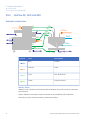
3.6.2
UniFlux 30, 120 and 400
External connections
P3
AS
TB3
P1
TB2
P2
P8
HTPN4
TB1
TB4
TME3
ME5
P7
P6
ME4
TME4
P5
B1
P4
Symbol
TP1
TP2
Color
Description
Blue
Outlets
Orange
Inlets
Cyan
Non-directional
Green
Interface points
Battery limits
"Battery limits" represents all interface points between the UniFlux and the customer
process plant.
System battery limits require hose connections not provided by GE Healthcare.
Normally, the user provides hoses for these connections.
72
UniFlux System Operating Instructions 28-9617-49 AC
3 System description
3.6 Flow charts
3.6.2 UniFlux 30, 120 and 400
Tag
Location
Function
Direction
AS
System
Air / nitrogen supply for integrity test
Inlet
HTPN4
Tank
Air / nitrogen supply for pressurization
(optional)
Inlet
ME4
System
Feed supply to transfer pump (optional)
Inlet
P2
System
Permeate
Outlet
P4
System
Feed drain
Outlet
P6
System
Retentate drain
Outlet
P7
System
Permeate drain
Outlet
P8
System
Filter drain (Only mounted/used in Hollow
fiber systems.)
Outlet
TME3,
TME4
Tank
Tank jacket media supply and return
(Only mounted/used in Hollow fiber systems.)
N/A
TP2
Tank
Feed drain
Outlet
Interface points
Diagram color: Green
Interface points provide process connections between the UniFlux system and the optional UniFlux tank. Hoses for these connections are normally delivered by GE Healthcare
as option to the tank delivery.
Tag
Function
Direction
ME5 - TB1
Feed from optional transfer pump to tank
System -> Tank
P1 - TB2
Retentate recycle
System -> Tank
P3 - TB3
Permeate recycle
System -> Tank
P5 - TB4
CIP media supply to tank
System -> Tank
TP1 - B1
Feed supply to system
Tank -> System
UniFlux System Operating Instructions 28-9617-49 AC
73
74
B1
P4
ME1
P-201
ME2
XV-061
P
P5
XV-062
PT-111
XV-001
F P
FT-141
XV-084
P3
PT-112
B5
B4
XV-083
XV-052
T P
P8
P7
XV-064
XV-065
FILTER
UV pH
T
P F C
PT-114
XV-082
P1
XV-063
TE-161
PCV-341
FA-231
CV-321
FT-142
B3
ME3
XV-051
T-342
F
PT-113
XV-081
P-202
ME5
P
CE/TE-101
B2
ME4
XV-041 PY-342
PS-342 FT-143
XV-031
P2
XV-032
P3
P-203
P2
3 System description
3.6 Flow charts
3.6.2 UniFlux 30, 120 and 400
Flowcharts
UniFlux 30
AE-121
AE-131
UniFlux System Operating Instructions 28-9617-49 AC
UniFlux System Operating Instructions 28-9617-49 AC
B5
XV-084
ME1
P-201
ME2
P4
XV-061
B1
P3
P
P5
XV-062
PT-111
XV-001
F P
FT-141
XV-083
XV-082
PT-112
B4
B3
XV-052
T P
FILTER
P8
P7
XV-064
XV-065
FILTER
UV pH
T
P F C
PT-114
ME3
XV-063
TE-161
PCV-341
FA-231
CV-321
PT-113
P1
XV-051
F
FT-142
XV-081
P-202
ME4
T-342
P
CE/TE-101
B2
ME3
XV-041 PY-342
PS-342 FT-143
XV-031
P2
XV-032
P3
P-203
P2
3 System description
3.6 Flow charts
3.6.2 UniFlux 30, 120 and 400
UniFlux 120
AE-131
AE-121
75
76
ME3
P
P6
ME2
ME1
P5
FT-141
F P
PT-112
XV-062
PT-111
XV-001
XV-052
T P
TE-161
PCV-341
FA-231
CV-321
XV-063
F
PT-113
P4
XV-051
T-342
P
FILTER
FILTER
FILTER
FILTER
P8
XV-065
P7
XV-064
UV pH
T
P F C
PT-114
P-201
P-202
ME4
FT-142
XV-061
P1
ME3
PS-342 FT-143
XV-041 PY-342
XV-084
XV-083
XV-082
XV-081
CE/TE-101
B1
B5
B4
B3
B2
FILTER
FILTER
XV-031
P2
XV-032
P3
P-203
P2
3 System description
3.6 Flow charts
3.6.2 UniFlux 30, 120 and 400
UniFlux 400
AE-121
AE-131
UniFlux System Operating Instructions 28-9617-49 AC
3 System description
3.6 Flow charts
3.6.2 UniFlux 30, 120 and 400
Tag / System
Function
Note
AE-121
Permeate pH-meter
Option
AE-131
Permeate UV-meter
Option
B1
Feed pump inlet
B2, B3, B4
Quadruple inlets 1, 2 and 3
B5
Quadruple inlet 4
CE-101
Permeate conductivity meter with an integrated temperature meter (TE-101)
CV-321
Filter integrity test check valve
FA-231
Filter integrity test sanitary filter
FILTER
Cross flow filter. Can be either hollow fibre
(HF) cartridge or filter cassette.
FT-141
Feed flow meter
FT-142
Permeate flow meter
FT-143
Filter integrity test flow meter
ME1
Feed pump coolant connection
ME2
Feed pump coolant connection
ME3
Quadruple inlet option outlet
Part of quadruple inlet option
ME4
Transfer pump inlet (from buffer)
ME5
Transfer pump outlet (to tank)
Part of transfer pump option
P1
Retentate outlet
P2
Permeate outlet, direct or by pump
P3
Permeate recycle
P4
Feed drain
P5
CIP valve
P6
Retentate drain
P7
Permeate drain
UniFlux System Operating Instructions 28-9617-49 AC
Part of quadruple inlet option
Option
Not included in system,
provided by customer or
sold separately.
77
3 System description
3.6 Flow charts
3.6.2 UniFlux 30, 120 and 400
Tag / System
Function
Note
P8
HF filter cartridge drain
HF configuration only
P-201
Feed pump
P-202
Feed transfer pump
Option
P-203
Transfer and permeate pump
Option
PCV-341
Retentate pressure control
PS-342
Filter integrity test pressure sensor
PY-342
Filter integrity test pressure regulator
PT-111
Feed pump outlet pressure meter
PT-112
Feed pump outlet pressure meter
PT-113
Retentate pressure meter
PT-114
Permeate pressure meter
TANK
Not included in system
T-342
Pressure regulator pulse damper
TE-101
Permeate temperature meter
XV-001
Pump feed valve
XV-031
Permeate outlet valve
XV-032
Permeate recycle valve
XV-051
Retentate outlet valve
XV-052
Retentate drain valve
XV-061
Feed drain
XV-062
Feed pressure outlet (CIP) valve
XV-063
Filter integrity test valve
XV-064
Permeate drain valve
XV-065
HF filter cartridge drain valve
78
Feed tank available as option
Option. Included in cond
CE-101.
HF configuration only
UniFlux System Operating Instructions 28-9617-49 AC
3 System description
3.6 Flow charts
3.6.2 UniFlux 30, 120 and 400
Tag / System
Function
Note
XV-081, 082, 083, 084
Quadruple inlet 1, 2, 3 and 4 valves
Part of quadruple inlet option
XY-342
Filter integrity test valve
In the flow diagram for UniFlux 400, the gray box represents the filter skid.
UniFlux System Operating Instructions 28-9617-49 AC
79
3 System description
3.7 UNICORN control system
3.7
UNICORN control system
Overview
UniFlux System is controlled by UNICORN process control software.
UNICORN can save established processes as methods. The methods include the
instructions necessary for process operation and documentation.
UNICORN includes a comprehensive system of user access levels to be programmed
limiting the operations a given user may perform on UniFlux System. To secure safe
operation of the system, you should limit access to the system to those qualified and
trained in its operation.
The UNICORN manual package provides complete instructions for programming and for
using the software for process control.
System operators are responsible for designing methods which conform to standard
operating procedures and Good Manufacturing Practice procedures.
UNICORN is compliant with FDA 21 CFR Part 11.
Knowledge prerequisite
At least basic knowledge of UNICORN is expected to operate UniFlux safely.
Information on how to use UNICORN can be obtained from the UNICORN User Manuals
and available tutorials. This manual does not cover how to use UNICORN.
Contact your local GE Healthcare representative for advice if required.
System networks
UNICORN can be installed on a stand-alone computer to control one to four locally
attached systems. However, the computer can only show one system at a time. Multiple
computers can view the output data from one system. UNICORN can also be installed
on a network.
80
UniFlux System Operating Instructions 28-9617-49 AC
3 System description
3.7 UNICORN control system
Software modules
The UNICORN control software consists of four modules:
Module
Function
UNICORN
Manager/Administration
File handling and administration tasks; for example, definition
of systems and managing user profiles.
Method Editor
Method creation and editing for preprogrammed control of
UniFlux System.
System Control
Process online control and monitoring using pre-defined
methods or manual control.
Evaluation
Evaluation and presentation of stored results.
Note:
The modules are active when the program is operating and are not closed
when minimized. A minimized System Control unit may control a process.
Workflow
The workflow for using UNICORN system for automatic control includes these general
steps:
Step
Action
1
Program an UniFlux System method run using the UNICORN software. It is
possible to use an existing method or modify an existing method to meet
your run objectives.
2
Start the run using the method you created.
3
Monitor the run's progress using the System Control module. All the data
about your run is displayed in the System Control module. You have a choice
of four different panes that can be open one at a time or all at once, in separate parts of the window.
4
After completing the run, you can display the data in a detailed report using
extensive tools provided by the UNICORN Evaluation Module.
UniFlux System Operating Instructions 28-9617-49 AC
81
3 System description
3.7 UNICORN control system
Cabinet controls and indicators
Typical image showing cabinet controls and indicators, for UniFlux 30 and 120 systems.
Label
Type
Color
Function
PAUSE
Button
Red
Sets UNICORN in PAUSE mode
(equal the PAUSE button in the
UNICORN computer user
interface)
CONTINUE
Button
Black
Sets UNICORN in RUN mode
(equal the CONTINUE button in
the UNICORN computer user
interface)
POWER
Indicator
Green
Power is on:
Flashing: UNICORN starting up.
Steady: UNICORN ready.
RUN/PAUSE
Indicator
Yellow
UNICORN method is active:
Flashing: UNICORN in state
pause.
Steady: UNICORN in state run.
ALARM
Indicator
Red
System alarm:
Check UNICORN for detailed information.
82
UniFlux System Operating Instructions 28-9617-49 AC
3 System description
3.7 UNICORN control system
Warnings
Warnings are generated to warn operating personnel that process parameters have
exceeded preset high and/or low limits, and that the process method continues.
Alarms
Signals
If equipment is connected that has lower limits than the system, the alarm levels must
be set accordingly.
If an analog or digital signal passes the predetermined alarm level, several things happen
at once:
•
An audible alarm is sounded (according to user preference settings).
•
The system is set to Pause mode.
•
The valves and other components on the system are set to their default positions.
Test
The alarm buzzer can be tested from the control system using the buzzer test function
Alarms:BuzzerTest.
To test a specific instrument alarm it is possible to lower the alarm limit for the instrument
below the current process value.
Reset
The alarm is reset through the control system by acknowledging the alarm message.
The process can be started again using the Continue function in UNICORN, if the situation
has been rectified.
More information
All required manuals are available from the UNICORN user interface. Select Help:Manuals
from the UNICORN top menu. The UNICORN user reference manual for BioProcess is
especially suited for usage with BioProcess systems.
UniFlux System Operating Instructions 28-9617-49 AC
83
4 Installation
4
Installation
About this chapter
This chapter provides required information to enable users and service personnel to
unpack, install, move and transport UniFlux System.
Precautions
WARNING
Before attempting to perform any of the procedures described in
this chapter, you must read and understand all contents of the
corresponding section(s) in the Chapter 2 Safety instructions, on
page 12 as listed below:
•
General precautions, on page 13
•
Personal protection, on page 15
•
Installing and moving, on page 16
•
Power supply, on page 19
In this chapter
This chapter contains the following sections:
Section
84
See page
4.1 Site requirements
85
4.2 Transport
87
4.3 Unpacking
88
4.4 Power supply
90
4.5 Setup
93
UniFlux System Operating Instructions 28-9617-49 AC
4 Installation
4.1 Site requirements
4.1
Site requirements
Space and floor load
For space and floor requirement, see external dimensions and weights in Section 9.1
Specifications, on page 150.
•
Make sure that the floor can handle the UniFlux System weight at fully loaded conditions. Please observe that for the weight to be equally distributed over all wheels,
the floor must be level and without irregularities.
•
In order to allow convenient working conditions for the operator, sufficient space
should be provided at all sides of the combined UniFlux System and UniFlux Tank
when installed at the intended production location.
Environmental requirements
•
The UniFlux System is intended for indoor use only.
•
The room must have forced ventilation.
•
Requirement regarding ambient air temperature is specified in the General Specification included in the system documentation kit.
Avoid:
•
Direct sunlight.
•
Strong magnetic or electric fields.
•
Vibrations.
•
Corrosive gas.
•
Dust.
Allowed ranges for environmental parameters are presented in Section 9.1 Specifications,
on page 150.
Electrical power
Refer to Section 4.4 Power supply, on page 90 and Section 9.1 Specifications, on page 150
for power, voltage and phase requirements.
UniFlux System Operating Instructions 28-9617-49 AC
85
4 Installation
4.1 Site requirements
Compressed air
•
Dry and particle free air for system supply.
•
Refer to Section 9.1 Specifications, on page 150 regarding capacity requirements.
Media supply
Refer to Section 9.1 Specifications, on page 150 regarding requirements on media supply
and delivery.
Supply must be arranged so that piping dimensions, piping lengths, valves and height
differences do not obstruct processing.
Battery limits
"Battery limits" represents all interface points between the UniFlux and the customer
process plant.
System battery limits require connections, not included in the GE Healthcare delivery.
Computer
An industrial built-in computer can be ordered as an option for UniFlux 30 and 120,
otherwise a stand-alone computer shall be used. When installing a stand-alone computer
ensure that it is installed with appropriate precautions for the intended environment
that might expose the computer to liquids and moisture.
NOTICE
Any computer used with the equipment shall comply with IEC 60950
and be installed and used according to the manufacturer's instructions.
86
UniFlux System Operating Instructions 28-9617-49 AC
4 Installation
4.2 Transport
4.2
Transport
In the transport crate
•
Use a pallet jack or fork lift with a minimum capacity to match the empty weight of
the system plus the transport box. Refer to Section 9.1 Specifications, on page 150
regarding system weight.
•
Make sure that intended openings and apertures are large enough to allow passage
of the box when lifted from the floor for transport.
For UniFlux 10: For minimum door aperture size, refer to Section 9.1 Specifications,
on page 150.
Unpacked
WARNING
Heavy object. Because of the significant weight of UniFlux System,
great care must be taken not to cause squeezing or crushing injuries during movement. At least two, but preferably three or more,
persons are recommended when moving the unit.
•
UniFlux can be rolled by hand on hard and level surface with wheel brakes released.
•
If the floor quality does no allow rolling the UniFlux on its own wheels, it can be moved
with a pallet jack or fork lift.
•
For minimum door aperture size, refer to Section 9.1 Specifications, on page 150.
UniFlux System Operating Instructions 28-9617-49 AC
87
4 Installation
4.3 Unpacking
4.3
Unpacking
Tools required
•
Suitable lifting device, fork lift or similar. Refer to Section 9.1 Specifications, on page 150
for dimensions and weight to be handled.
•
13 mm wrench (or ratchet with 13 mm socket).
•
Electrical screwdriver with Phillips no. 2 bit.
•
Knife.
•
Lever (enclosed in crate).
Visual inspection
Check:
•
that all equipment is enclosed in the crate according to the packing list.
•
the equipment for any apparent damage and document carefully if found.
If any equipment is missing or damages are found, contact your GE Healthcare representative immediately.
Precautions
WARNING
To prevent bacterial growth, UniFlux System may be partly filled
with denatured Ethanol (18% C2H5OH (Ethanol), 2% C3H7OH (Isopropanol) and 80% H2O (water)) or 0.1 M NaOH (Sodium Hydroxide)
at delivery.
Flush out the denatured Ethanol or Sodium Hydroxide before assembling, testing or integrating UniFlux into the intended process
context.
88
UniFlux System Operating Instructions 28-9617-49 AC
4 Installation
4.3 Unpacking
General unpacking instructions
Note:
Refer to the unpacking instructions attached to the outside of the crate when
unpacking the crate. In absence of the unpacking instructions, follow the
general unpacking instructions below.
Step
Action
1
Remove the front, side and back panels by loosening the bolts.
2
Remove the ramp, accessories, user console and documentation package.
3
Attach the ramp on the cabinet side of the crate.
4
Remove the brackets on the cabinet side.
5
Carefully roll the system out of the crate.
UniFlux System Operating Instructions 28-9617-49 AC
89
4 Installation
4.4 Power supply
4.4
Power supply
Power requirements
The power supply requirements are specified in Section 9.1 Specifications, on page 150.
Installation
Connect the system power cord to a fixed power supply by means of a permanent
connection which can be detached only by the use of a tool.
WARNING
Electrical power. All electrical installations must be performed by
authorized personnel only.
Grounding and protective earth
•
The protective earth wire must be connected to system ground.
•
Ground impedance must conform to the requirements of national and local industrial
safety regulations and/or electrical codes.
•
If the leak current exceeds 10 mA, a high leakage current earth connection must be
provided and confirmed before connecting power supply.
•
The integrity of all ground connections must be periodically checked.
Circuit breaker
A circuit breaker must be present in the fixed power supply.
Breaking the power supply to the UniFlux System by using this breaker must be eqvivalent
to disconnecting the power cord for a non-fixed connected instrument.
90
UniFlux System Operating Instructions 28-9617-49 AC
4 Installation
4.4 Power supply
Power supply cable
The mains power supply cable is shielded ÖLFLEX™ of type: 150CY Quattro (3G x 2.5 mm2,
G = with PE conductor, X = without PE conductor)
If the cable needs to be replaced due to damage, the same type of cable or equivalent
must be used.
WARNING
Only personnel authorized by GE Healthcare may perform service,
installation, and maintenance of components inside the UniFlux
cabinet.
Wire colors and tags
All instrument power cord wires must be connected to the fixed power supply wires with
corresponding colors and tags.
Function
USA
EU
Marking
Neutral
White
Blue
N
Live
Black
Black or
brown
L
Protective
ground (earth)
Green
Green/yellow
PE = GND
Live and neutral wire cross
section area
All live- and neutral wiring must have a cross section area equal to or more than the
specification in this table:
Mains current
up to
Mains and neutral conductor
minimum area
10 A
1 mm2
16 A
1.5 mm2
25 A
2.5 mm2
UniFlux System Operating Instructions 28-9617-49 AC
91
4 Installation
4.4 Power supply
Protective earth wire cross
section area
All protective earth wiring must have a cross section area equal to or more than the
specification in this table:
Leak current
PE conductor minimum area
> 10 mA
10 mm2 copper or 16 mm2 aluminium
≤ 10 mA
Equal to or larger than the L and N-wire
Ground fault breaker
UniFlux System is not equipped with a general Ground Fault Circuit Breaker and it is not
an option that is available from GE Healthcare.
However, if ground fault protection for the system is desired,
•
a Ground Fault Circuit Interruptor may be installed, or
•
the system may be connected to an outlet that is protected by a permanently installed
Ground Fault Circuit Breaker.
The tripping current for such an interrupter must be higher than the leak current as
found in the test protocol in the system documentation kit.
Built-in circuit breakers
The mains power supply to the UniFlux system and the pumps are equipped with circuit
breakers inside the cabinet. Refer to the System Documentation for the specific types
used in your system.
More information
Voltage, power, fuse requirements and the tripping current for the fixed power supply
ground fault protector can be found in the General Specification, provided with the system
document package.
92
UniFlux System Operating Instructions 28-9617-49 AC
4 Installation
4.5 Setup
4.5
Setup
Precautions
WARNING
To prevent bacterial growth, UniFlux System may be partly filled
with denatured Ethanol (18% C2H5OH (Ethanol), 2% C3H7OH (Isopropanol) and 80% H2O (water)) or 0.1 M NaOH (Sodium Hydroxide)
at delivery.
Flush out the denatured Ethanol or Sodium Hydroxide before assembling, testing or integrating UniFlux into the intended process
context.
In this section
This section contains the following subsections:
Section
See page
4.5.1 Lock wheels
94
4.5.2 Operator console for UniFlux 30, 120 and 400
95
4.5.3 Stand-alone computer for UniFlux 10
98
4.5.4 Connect compressed air supply
99
4.5.5 Setup of control system and network
100
4.5.6 Filter setup, feed pump and CFF filter protection
101
4.5.7 Process component connections for UniFlux 30, 120 and 400
102
UniFlux System Operating Instructions 28-9617-49 AC
93
4 Installation
4.5 Setup
4.5.1 Lock wheels
4.5.1
Lock wheels
After positioning the system at its designated location, lock the wheels (figure).
94
UniFlux System Operating Instructions 28-9617-49 AC
4 Installation
4.5 Setup
4.5.2 Operator console for UniFlux 30, 120 and 400
4.5.2
Operator console for UniFlux 30, 120 and 400
Introduction
The operator console is packed separately in a cardboard box which is enclosed in the
system crate for UniFlux 30 and 120.
All connections to and from the monitor and the keyboard (DVI signal, USB connection
and power) are included in one multi-conductor cable (ODU minisnap 24-pin connector).
One ODU minisnap 3-pin connector is used for the power supply.
These two cables are attached to the system located underneath the cabinet.
Precautions
CAUTION
Make sure that the console arm is firmly positioned with the top
part of the handle fully inserted, so that the bushing is able to absorb the weight of the console when the console arm is fully extended. The console may fall and cause damage and/or injury if the
console arm is not properly positioned.
NOTICE
Operator console
•
Do not use the operator console to push or drag the system
•
Do not lean on the console
The console arm is only designed to support the weight of the
operator console.
Mount the console to the system
At arrival to the production site, the user console is packed separately and needs to be
assembled to the system skid. Refer to Section 4.5.2 Operator console for UniFlux 30, 120
and 400, on page 95. Except for the console, the UniFlux System is delivered fully assembled at production site arrival. No further specific assembly procedures are required.
Follow this sequence when mounting the operator console to the UniFlux 30 and 120
systems:
UniFlux System Operating Instructions 28-9617-49 AC
95
4 Installation
4.5 Setup
4.5.2 Operator console for UniFlux 30, 120 and 400
Step
Action
1
Open the box and remove the assembled console. Do not remove the styrofoam protection, this can be used for lifting.
2
Carefully slide the console arm over the system handle (B) until it is firmly
attached. Keep the styrofoam protection (A) in place when attaching the
console arm.
A
B
3
96
Remove the styrofoam protection.
UniFlux System Operating Instructions 28-9617-49 AC
4 Installation
4.5 Setup
4.5.2 Operator console for UniFlux 30, 120 and 400
Step
Action
4
Attach the two ODU minisnap connectors (C) to the console as shown in the
picture.
C
D
NOTICE
The protective screw cap (D) should always be in place
when the USB connector is not in use.
5
Press the Rotation Stop on to the console arm as shown in the picture and
push it into place around the rotation center.
UniFlux System Operating Instructions 28-9617-49 AC
97
4 Installation
4.5 Setup
4.5.3 Stand-alone computer for UniFlux 10
4.5.3
Stand-alone computer for UniFlux 10
Connect a stand-alone computer
to UniFlux 10
Connect a stand-alone computer with UNICORN to UniFlux by plugging in an Ethernet
cable to the UNICORN ETHERNET connector illustrated below.
Note:
98
When installing a stand-alone computer ensure that it is installed with appropriate precautions for the intended environment that might expose the computer to liquids and moisture.
UniFlux System Operating Instructions 28-9617-49 AC
4 Installation
4.5 Setup
4.5.4 Connect compressed air supply
4.5.4
Connect compressed air supply
Locate your air inlet and air exhaust and connect to the compressed air supply.
For requirements on air supply, refer to Section 4.1 Site requirements, on page 85.
UniFlux System Operating Instructions 28-9617-49 AC
99
4 Installation
4.5 Setup
4.5.5 Setup of control system and network
4.5.5
Setup of control system and network
Introduction
This section describes the steps that need to be performed to set up the UNICORN control
system and network connections.
Install UNICORN
Make sure that the UniFlux control software UNICORN is installed on your computer. A
system must be defined, and the UniFlux configuration or strategy must be installed.
Refer to UNICORN Administration and Technical manual for more information.
Install Controller Unit 960
(CU-960)
The CU-960 is part of the UniFlux system at the delivery. It is an external control unit that
communicates with UNICORN via Ethernet connection.
To use the Ethernet connection, the CU-960 must be set up like a network device with
IP address, default gateway and subnet mask address.
Refer to the control unit manual for more information.
100
UniFlux System Operating Instructions 28-9617-49 AC
4 Installation
4.5 Setup
4.5.6 Filter setup, feed pump and CFF filter protection
4.5.6
Filter setup, feed pump and CFF filter protection
Filter setup
If the system is configured for the intended filter type (HF or cassette), no need for further
installations are required at arrival to the process site or between processing.
Feed pump and CFF filter
protection
To protect the system from feed containing particles that may clogg the CFF-filter or
damage the pump, use upstream normal flow filtering.
NOTICE
Do not use an in-line filter screen on the piping between the recirculation tank and the feed pump. If such a filter screen becomes
clogged, the flow to the feed pump will be restricted and the pump
may be damaged because of cavitation.
UniFlux System Operating Instructions 28-9617-49 AC
101
4 Installation
4.5 Setup
4.5.7 Process component connections for UniFlux 30, 120 and 400
4.5.7
Process component connections for UniFlux 30, 120 and
400
Introduction
This section provides guidelines for the connection of process components to UniFlux
30, 120 and 400 systems.
Typical hook up, all options
included
1
2
3 4
5
6 7
The image shows the typical hook up for the UniFlux 30 and 120 systems.
102
Part
Function
From
To
1
Permeate output
UniFlux system permeate pump
Plant downstream process or waste
2
Permeate recycle
UniFlux system
UniFlux tank
UniFlux System Operating Instructions 28-9617-49 AC
4 Installation
4.5 Setup
4.5.7 Process component connections for UniFlux 30, 120 and 400
Part
Function
From
To
3
Retentate recycle
UniFlux system
UniFlux tank
4
Transfer of media
UniFlux system transfer
pump
UniFlux tank
5
Transfer of media (not
visible)
Plant upstream process
UniFlux system transfer
pump
6
Permeate output
UniFlux system
UniFlux system permeate pump
7
CIP media
UniFlux system
UniFlux tank
UniFlux System Operating Instructions 28-9617-49 AC
103
5 Run preparations
5
Run preparations
About this chapter
This chapter provides the information required to safely prepare the UniFlux System for
operation.
Before the UniFlux System is taken into operation, make sure that all procedures in the
following chapter and section have been performed:
•
Chapter 4 Installation, on page 84 and
•
actions before operation in Section 7.1 User maintenance schedule, on page 131.
Precautions
WARNING
Before attempting to perform any of the procedures described in
this chapter, you must read and understand all contents of the
corresponding section(s) in the Chapter 2 Safety instructions, on
page 12 as listed below:
•
General precautions, on page 13
•
Personal protection, on page 15
•
System operation, on page 20
NOTICE
Only use chemicals that have been proven not to be harmful to
the wetted parts of the unit.
Refer to Section 9.3 Chemical resistance, on page 157 for more information.
104
UniFlux System Operating Instructions 28-9617-49 AC
5 Run preparations
In this chapter
This chapter contains the following sections:
Section
See page
5.1 Starting UniFlux
106
5.2 Filter installation
108
5.3 Priming and testing
119
UniFlux System Operating Instructions 28-9617-49 AC
105
5 Run preparations
5.1 Starting UniFlux
5.1
Starting UniFlux
Starting UniFlux
Step
Action
1
Make sure that the air supply to the system is turned on.
2
Turn on the UPS if used.
3
Make sure that the cabinet doors are closed and locked.
4
Switch on power to UniFlux by turning the Mains power switch to the "I"
position. See Section 3.2 UniFlux systems layout, on page 42 for location.
5
Make sure that UNICORN is started according to the instruction in Starting
UNICORN, on page 106. Wait for connection.
After this sequence is completed, the following occurs:
•
The computer is turned on.
•
The POWER indicator lamp flashes.
•
When communication with UNICORN software is established, the POWER indicator
lamp shows a steady green light.
Starting UNICORN
Refer to Section 3.7 UNICORN control system, on page 80 for more information regarding
the UNICORN control system, warnings and alarms.
Step
Action
1
Switch on the computer.
2
Log on to Microsoft™ Windows™.
3
Start UNICORN by double-clicking on the UNICORN icon on the Windows
desktop.
4
When the Logon dialog appears, select a user from the Users list and enter
the password.
If you log on for the very first time, select default and enter the password
default.
106
5
Click OK.
6
In the System Control module, select System:Connect.
UniFlux System Operating Instructions 28-9617-49 AC
5 Run preparations
5.1 Starting UniFlux
Step
Action
7
In the dialog shown, select the appropriate system name and click OK. The
system name is specified during installation configuration.
8
When UNICORN is connected to the system, the Run button in the status
bar is enabled. The button initially has a green color indicating the system
is ready to run.
UniFlux System Operating Instructions 28-9617-49 AC
107
5 Run preparations
5.2 Filter installation
5.2
Filter installation
In this section
This section contains the following subsections:
Section
108
See page
5.2.1 Installing hollow fiber (HF) cartridges
109
5.2.2 General preparation of the cassettes
110
5.2.3 Cassettes for UniFlux 10
111
5.2.4 Cassettes for UniFlux 30, 120 and 400
113
UniFlux System Operating Instructions 28-9617-49 AC
5 Run preparations
5.2 Filter installation
5.2.1 Installing hollow fiber (HF) cartridges
5.2.1
Installing hollow fiber (HF) cartridges
Follow the instruction below to install the HF cartridges.
Step
Action
1
Make sure that the system is configured for using HF cartridges and of the
intended size.
2
Prepare the HF cartridge(s) according to the manufacturer's instructions.
3
Install the cartridge into the system, refer to illustrations in Section 3.5 Hollow
fiber (HF) configuration, on page 62.
UniFlux System Operating Instructions 28-9617-49 AC
109
5 Run preparations
5.2 Filter installation
5.2.2 General preparation of the cassettes
5.2.2
General preparation of the cassettes
The table below describes general preparations before installing the cassettes.
Step
Action
1
If the filter cassettes to be used are new, it is strongly recommended to
perform an air integrity test to establish its characteristic
air or nitrogen flow. See Air integrity test, on page 120 for instructions.
2
110
Prepare and check the cassettes according to the manufacturer's instructions.
UniFlux System Operating Instructions 28-9617-49 AC
5 Run preparations
5.2 Filter installation
5.2.3 Cassettes for UniFlux 10
5.2.3
Cassettes for UniFlux 10
Preparations
Loosen the retaining nuts and slide the back plate far enough away from the forward
fixed distribution plate to accomodate the total amount of Kvick Lab cassettes to be
used for the filtration run.
Installation
Note:
This assembly instruction applies to GE Healthcare cassettes only. For information on installing other cassettes, please contact your local GE Healthcare
representative.
Step
Action
1
To install one cassette, clean and wet a silicone gasket by rinsing it with
deionized (DI) water or water-for-injection (WFI).
2
Place the gasket against the flow distribution manifold, aligning the holes
in the gasket with the holes in the manifold. The gasket will stick to the
manifold.
3
From the top, place the cassette into the holder with the gasket-side of the
cassette facing the backing plate, and slide the cassette against the gasket.
4
Place the second cassette into the holder between the first cassette and the
backing plate. Ensure the gasket-side of the second cassette faces the
backing plate. Place subsequent cassettes in the holder in similar fashion.
No gasket required
Gasket
Smooth side
UniFlux System Operating Instructions 28-9617-49 AC
111
5 Run preparations
5.2 Filter installation
5.2.3 Cassettes for UniFlux 10
Tighten the cassette assembly
112
Step
Action
1
Slide the back plate towards the cassettes until they make contact.
2
Screw the 2 retaining nuts by hand until the backplate is pressing against
the cassettes. Make sure that the back plate is sliding orthogonally.
3
Tighten the 2 retaining nuts in small increments in a cross-wise pattern until
the torque 20 Nm is reached. Make sure that the nuts are tightened equally
to prevent uneven pressure over the cassettes.
UniFlux System Operating Instructions 28-9617-49 AC
5 Run preparations
5.2 Filter installation
5.2.4 Cassettes for UniFlux 30, 120 and 400
5.2.4
Cassettes for UniFlux 30, 120 and 400
Hydraulic pressure
Make sure that the hydraulic pressure required to prevent filter leakage with sufficient
margin is known.
NOTICE
Too high hydraulic pressure will have a negative effect on the
pressure drop caused by the cassette and can cause damages on
the cassettes.
The hydraulic pressure shall be restricted to 140 bar (2000 psi) to avoid overload of
cassette holder.
For all filter cassettes, empirical testing is needed to decide what hydraulic pressure to
use. Contact your GE Healthcare representative for advice.
Preparations
Step
Action
1
Prepare and check the cassettes according to the manufacturer's instructions.
UniFlux System Operating Instructions 28-9617-49 AC
113
5 Run preparations
5.2 Filter installation
5.2.4 Cassettes for UniFlux 30, 120 and 400
Step
Action
2
Make sure that:
UNICORN is started and the
Yellow system status light
RUN/PAUSE is on and
steady.
The hydraulic unit is
switched on.
The key on the hydraulic
unit front side is switched
to ON and the white POWER light is on.
114
UniFlux System Operating Instructions 28-9617-49 AC
5 Run preparations
5.2 Filter installation
5.2.4 Cassettes for UniFlux 30, 120 and 400
Step
Action
3
Move the filter pressurization cylinder backwards by simultaneously pressing
the ENABLE and DEPRESSURIZE buttons on the hydraulic unit.
4
Remove any hydraulic piston extensions attached to the hydraulic piston
by unscrewing the extensions.
5
Slide the cassette holder pressurization back plate backwards by hand until
it meets the hydraulic cylinder piston.
UniFlux System Operating Instructions 28-9617-49 AC
115
5 Run preparations
5.2 Filter installation
5.2.4 Cassettes for UniFlux 30, 120 and 400
Step
Action
6
Slide back the sleeve on the movable guide rod and lift the guide rod up.
7
Install one or both hydraulic piston extensions by screwing them into the
end of the hydraulic piston using this schedule as a guide:
•
1 to 4 cassettes, use the 2-inch and 4-inch extensions.
•
5 to 10 cassettes, or 1 to 2 block cassettes (block cassettes are the 2.33
m² {25 ft²}, use the 4-inch extension.
•
10 to 15 cassettes, or three block cassettes, do not use an extension.
•
Other combinations of cassettes, choose a combination of extenders
that will enable the backing plate to slide up to the cassettes, while still
providing about three inches of piston travel when the hydraulic cylinder
is pressurized.
Installation
Note:
116
This assembly instruction applies to GE Healthcare cassettes only. For
information on installing other cassettes, please contact your local GE
Healthcare representative.
Step
Action
1
To install one cassette, clean and wet a silicone gasket by rinsing it with DI
water or water-for-injection (WFI).
2
Place the gasket against the flow distribution manifold, aligning the holes
in the gasket with the holes in the manifold. The gasket will stick to the
manifold.
UniFlux System Operating Instructions 28-9617-49 AC
5 Run preparations
5.2 Filter installation
5.2.4 Cassettes for UniFlux 30, 120 and 400
Step
Action
3
From the top, place the cassette into the holder with the gasket-side of the
cassette facing the backing plate (hydraulic cylinder), and slide the cassette
against the gasket.
4
Place the second cassette into the holder between the first cassette and the
backing plate. Ensure the gasket-side of the second cassette faces the
backing plate. Place subsequent cassettes in the holder in similar fashion.
Gasket
No gasket required
Smooth side
5
After you insert all the cassettes into the holder, lower and lock the guide
rod into its original position.
6
Slide the backing plate and cassettes towards the flow manifold, ensuring
the holes in the cassettes and gasket are aligned with the holes in the flow
distribution manifold.
Pressurization
WARNING
To avoid the possibility of crushing, notify all assistants to clear the
holder area and visually ensure no assistant is working on the
holder before energizing the hydraulic pump.
UniFlux System Operating Instructions 28-9617-49 AC
117
5 Run preparations
5.2 Filter installation
5.2.4 Cassettes for UniFlux 30, 120 and 400
Using the hydraulic pump, pressurize the hydraulic cylinder according to the previously
performed calculation.
118
UniFlux System Operating Instructions 28-9617-49 AC
5 Run preparations
5.3 Priming and testing
5.3
Priming and testing
Introduction
Before using your UniFlux system and cassette to process product, do the following:
1
For UniFlux 30, 120 and 400: Prime the lobe rotor pump.
2
Perform a leakage test.
3
Perform an air integrity test.
Priming the lobe rotor pump
Priming is done for UniFlux 30, 120 and 400.
NOTICE
Do not start the lobe rotor pump before it is primed with the
intended media.
The CIP valve (XV-062) is used in order to prime the lobe rotor pump.
Step
Action
1
Connect the suction side of the pump to the intended feed supply. FILTER
2
Make sure that waste ejected from the CIP valve outlet is collected.
3
Open the CIP valve.
PT-112
P5
PT-112
PT-111
XV-001
XV-062
P-201
4
Run the pump while watching the flow through the transparent waste hose
from the CIP valve.
5
When liquid only and no air exits the CIP valve, stop the pump and close the
CIP valve.
XV-061
UniFlux System Operating Instructions 28-9617-49 AC
B1
P4
119
5 Run preparations
5.3 Priming and testing
Leakage test
Step
Action
1
Pressurize the system up to the maximum intended process pressure. For
GE Healthcare Kvick Flow and Kvick Lab cassettes, maximum system
pressure is 4.15 bar g (60 psi g).
2
Watch the system for leaks while maintaining this pressure. Pay special
attention to the filter installation.
If a leak-free seal is not achieved at this pressure, there may be a cassette,
gasket, or surface finish irregularity. Proceed as follows:
3
Remove the filters and inspect the sealing surfaces.
4
Correct any found problem, reinstall the filters and perform the test again.
Air integrity test
It is recommended to perform an air integrity test on each filter before usage.
All instructions below are performed in UNICORN.
Step
Action
1
Prepare the system for the test:
2
3
120
1
Flush the system and filter with water or buffer.
2
Drain the system from all fluid.
3
Make sure that process grade air supply to the integrity test is connected
and turned on, refer to Section 4.5.4 Connect compressed air supply, on
page 99.
Isolate the upstream process by closing the following valves:
•
Feed valve XV-001.
•
Retentate pressure control valve PCV-341.
•
Retentate valve XV-051.
Open the Permeate valve XV-031 to Permeate.
UniFlux System Operating Instructions 28-9617-49 AC
5 Run preparations
5.3 Priming and testing
Step
Action
4
NOTICE
Never let the test pressure exceed the maximum filter
pressure as stated by the filter manufacturer. If the filter is subjected to pressures exceeding this value, unrecoverable damage may occur.
Apply air pressure to the filter:
1
Set the Integrity_Test_Pressure to the pressure specified by the filter
manufacturer.
2
Open the Integrity test valve XV-063.
Note:
If the pressure as indicated by PT-113 takes more than 15 minutes to build
up and stabilize, this indicates that there is a leak somewhere in the system.
Identify and seal all leakages before proceeding with the test.
5
6
7
When the specified test pressure has been reached:
1
Wait for a stable air flow reading from the flow meter FT-143.
2
Compare this value to the integrity air flow value specified by the filter
manufacturer.
Terminate the air integrity test:
1
Set Integrity_Test_Pressure to zero.
2
Close the integrity test valve XV-063.
3
Open the retentate valve XV-051.
4
Open the Retentate drain valve XV-052.
Open the retentate pressure valve PCV-341 in small increments to protect
the filter.
When the PT-113 pressure indicator reads zero, the system is depressurized
and the test procedure completed.
Unexpected flowrate
If the flow deviates from the characteristic flow during an air integrity test, the following
conclusions can be drawn:
UniFlux System Operating Instructions 28-9617-49 AC
121
5 Run preparations
5.3 Priming and testing
If...
Then...
The air/nitrogen flow is significantly lower than the characteristic flow.
The filter is clogged and needs to be cleaned.
The air/nitrogen flow is significantly higher than the characteristic flow.
The are pores in the membranes or fibers that
have become larger than the nominal pore size.
or
The fibers or membranes are broken.
The filter will allow larger particles than the nominal cut-off size to pass to the permeate and must
hence not be used for processing any more.
122
UniFlux System Operating Instructions 28-9617-49 AC
6 Operation
6
Operation
About this chapter
This chapter provides the information required to safely operate the UniFlux System.
Precautions
WARNING
Before attempting to perform any of the procedures described in
this chapter, you must read and understand all contents of the
corresponding section(s) in the Chapter 2 Safety instructions, on
page 12 as listed below:
•
General precautions, on page 13
•
Personal protection, on page 15
•
System operation, on page 20
UniFlux System Operating Instructions 28-9617-49 AC
123
6 Operation
NOTICE
Only use chemicals that have been proven not to be harmful to
the wetted parts of the system.
Refer to Section 9.3 Chemical resistance, on page 157 for more information.
In this chapter
This chapter contains the following sections:
Section
124
See page
6.1 Perform the run
125
6.2 Procedures after usage
128
UniFlux System Operating Instructions 28-9617-49 AC
6 Operation
6.1 Perform the run
6.1
Perform the run
Precautions
WARNING
During operation, all doors must always be closed and locked.
CAUTION
Use ear protection whenever working close to the system in operation.
NOTICE
Operator console
•
Do not use the operator console to push or drag the system
•
Do not lean on the console
The console arm is only designed to support the weight of the
operator console.
NOTICE
Excessive temperatures may damage the equipment. Do not run
the system at higher temperatures than the specified maximum
operation temperature as stated on the system label.
Final checks before start
NOTICE
Make sure that the actions listed below are completed before
UniFlux is started.
UniFlux System Operating Instructions 28-9617-49 AC
125
6 Operation
6.1 Perform the run
•
Check that the pump is filled with correct lubricant oil before start, refer to the pump
supplier documentation found in the document package for details.
•
Check that all inlets and outlets to the system are connected, closed or in the state
that they are supposed to be before the system is started.
-
Inlets that are not in use shall be closed.
-
Outlets that are not in use shall be fitted with tubing and directed to waste.
•
Check the condition of all connections and gaskets.
•
Check that no chemicals that may be harmful to the system will be used.
•
Perform an alarm test according to Test, on page 83.
Starting
Step
Action
1
In the UNICORN System Control module, select Run in the File menu.
2
Select the method to start. Click OK.
A Start Protocol is displayed, consisting of a number of dialog boxes. On the
Variables page, it is possible to fine-tune the method before proceeding.
Checking the Show details box will display more detailed information.
3
Check that the sample volume is correct.
4
Click Next or Back to navigate through the dialog panels, adding the information required as well as your own comments.
5
Click the START button in the Result Name dialog box. This will initiate the
method run.
Note:
The pump needs a completely open flow path to enable start.
Monitoring
The progress of the run can be viewed in detail in the UNICORN System Control module.
Up to four different panels can simultaneously display different aspects of the run. To
customize content and layout of a panel, right-click in it and select Properties... from
the menu displayed. By selecting Documentation: Run notes, it is possible to add notes
during a run. Entered notes will be included in the results.
More information regarding the monitoring possibilites that the UNICORN user interface
offers is available in the UNICORN manual package.
126
UniFlux System Operating Instructions 28-9617-49 AC
6 Operation
6.1 Perform the run
Ending
Normal completion
If no unexpected events occur during the run, UNICORN enters END state at method
completion without need for user interaction.
End before method has finished
To end the run before the method has finished, click on the End button at the top of the
Control module window.
This will produce a confirmation dialog. Click OK in the dialog to end the run, or click
Cancel to keep running.
In the dialog, you can choose to save the (partial) results from the run so far. If the run
is part of a scouting run, you are also given the choice of ending this. (If you do not, the
next run will start automatically.)
UniFlux System Operating Instructions 28-9617-49 AC
127
6 Operation
6.2 Procedures after usage
6.2
Procedures after usage
Cleaning the filters
The filters can be cleaned in place if the method is set within the specifie ranges for
solutions, temperature and pressure. The filters should be cleaned as described in Filters
, on page 134.
UNICORN shut-down
Step
Action
1
In UNICORN, select File:Quit or click the Close icon in the Manager/Administration module.
2
Confirm that you want to quit and select to leave system locked or unlocked.
3
Exit Windows.
4
Turn off the system power switch.
Note:
Since the system power will be shut down, the system cannot be operated
from another workstation before the system is powered up again, regardless
if it is locked or unlocked at shut down.
Preparing for storage
Prepare the system for storage as described in Section 7.3 Storage, on page 136 as
required.
128
UniFlux System Operating Instructions 28-9617-49 AC
7 Maintenance
7
Maintenance
About this chapter
This chapter provides required information to enable users and service personnel to
clean, maintain, calibrate and store the UniFlux System.
In this chapter
This chapter contains the following sections:
Section
See page
7.1 User maintenance schedule
131
7.2 Cleaning
133
7.3 Storage
136
7.4 Disassembly and assembly
138
7.5 pH calibration
140
UniFlux System Operating Instructions 28-9617-49 AC
129
7 Maintenance
Precautions
WARNING
Before attempting to perform any of the procedures described in
this chapter, you must read and understand all contents of the
corresponding section(s) in the Chapter 2 Safety instructions, on
page 12 as listed below:
130
•
General precautions, on page 13
•
Personal protection, on page 15
•
Power supply, on page 19
•
Maintenance, on page 22
UniFlux System Operating Instructions 28-9617-49 AC
7 Maintenance
7.1 User maintenance schedule
7.1
User maintenance schedule
Before each run or weekly
This section covers maintenance actions required for each run or weekly (depending on
which happens first).
Component
Action
UV monitor
Set auto-zero by using the function in UNICORN.
pH monitor
Clean, calibrate and store the pH electrode adequately, refer
to Section 7.5 pH calibration, on page 140.
Alarm buzzer
Check the function Alarms:BuzzerTest.
Complete system
Clean/sanitize the system according to the procedure described
in Cleaning-in-place (CIP), on page 133.
Protective earth
Make sure that the protective earth wiring is not disconnected
or damaged.
Annually or as needed
This section covers maintenance actions required annually or as needed.
Component
Action
Complete system
A preventive maintenance test procedure on all instruments,
sensors, pumps and valves should be performed annually by
trained and certified personnel. Contact your local GE
Healthcare representative. Replace all gaskets, o-rings and
valve diaphragms.
Complete stainless
steel system
Inspect stainless steel systems for rust. If needed, passivate
the steel by recirculating a solution of 5% phosphoric acid in
the system overnight at room temperature and then rinse with
purified water until the pH of the outlet liquid is neutral.
Pump
Replace all wear and tear parts. Replace drive element lubricant.
Refer to the System Documentation for details.
UV monitor
Replace the UV lamp when the intensity is low or when a lamp
failure is indicated in UNICORN.
pH/Cond monitor
Replace the pH electrode if difficulties are experienced during
calibration.
UniFlux System Operating Instructions 28-9617-49 AC
131
7 Maintenance
7.1 User maintenance schedule
132
Component
Action
Cond monitor
Clean and calibrate the cond monitor.
UniFlux System Operating Instructions 28-9617-49 AC
7 Maintenance
7.2 Cleaning
7.2
Cleaning
General
A suitable frequency of routine cleaning is determined by the nature of the starting
material and the type of process. However, routine cleaning shall be performed at
intervals aimed at prevention rather than cleaning UniFlux (and connected equipment)
from growth or contamination.
Recommended cleaning agents
All components can be cleaned with the most commonly used agents, such as detergents,
Ethanol, weak acids, Sodium Hydroxide and salt solutions.
Refer to Section 9.3 Chemical resistance, on page 157.
NOTICE
Avoid Sodium Chloride solutions below pH 4.0. Rinse UniFlux thoroughly with water immediately after contact with salt solutions, to
lessen the risk of corrosion.
Cleaning before
maintenance/service
Before maintenance/service is performed, the system owner must first clean the system
and complete a Health & Safety Declaration Form. Contact GE Healthcare for further
information.
Cleaning-in-place (CIP)
CIP hookup
Applies to UniFlux 30, 120 and 400.
The UniFlux system and Tank combination is preferably cleaned together as one unit.
The UniFlux system feed outlet P5 / CIP shall be connected to the tank CIP-ball inlet TB4
/ CIP INLET using the provided hose. Ensure proper position of the ball using the
positioning marks.
UniFlux System Operating Instructions 28-9617-49 AC
133
7 Maintenance
7.2 Cleaning
Refer to UniFlux Feed Tank Operating Instructions for information on how to clean the
Tank.
CIP methods in UNICORN
It is recommended that specific CIP-protocols are developed to standardize the CIPprocedure in a repeatable and reliable manner depending on the applied user application.
A routine cleaning method can be set up in UNICORN for regular cleaning and sanitizing
of the system and connected components.
Refer to UNICORN manual package for comprehensive instructions on how to create a
sanitizing/CIP method in UNICORN.
Extended cleaning performance
If the UniFlux System has been heavily contaminated and the normal CIP-procedure is
not sufficient, cleaning performance can be improved by:
•
Extending the total CIP time period.
•
Changing to an alternative CIP-agent.
•
Filling the UniFlux System and attached components with cleaning agent to redissolve
contaminants for an extended time period before applying CIP.
Rinsing
After completed CIP, rinse the UniFlux System interior and all cleaned components
thoroughly with water of desired quality, for example Water For Injection (WFI), to remove
all traces of the cleaning agent.
Filters
•
GE Healthcare Kvick Lab cassettes cleaning procedures are provided in the Kvick
Lab and Kvick Flow Cassettes User Manual, GE Healthcare article no 18-1171-69.
GE Healthcare Kvick Lab and Kvick Flow cassettes cleaning procedures are provided
in the Kvick Lab and Kvick Flow Cassettes User Manual, GE Healthcare article no
18-1171-69.
134
•
GE Healthcare Hollow fiber cartridges cleaning procedures are provided in the Hollow
fiber cartridges for membrane separations Operating Handbook, GE Healthcare article
no 18-1165-30.
•
Filter units provided by other manufacturers shall be cleaned according to the instructions from the respective manufacturer.
UniFlux System Operating Instructions 28-9617-49 AC
7 Maintenance
7.2 Cleaning
External surfaces
The UniFlux System is designed to be operated in a clean environment and the external
surfaces should not normally accumulate any substantial amount of dust or dirt.
Regularly, wipe the outside of the UniFlux System with a clean cloth. Use a mild cleaning
agent such as water, followed by 70% Ethanol. Regular wiping and care of the equipment
will help keep the surfaces uncorroded.
It is not recommended to spray or splash liquids towards external surfaces.
Do not spray or splash liquids towards filters or the fan on the electric cabinet.
UniFlux System Operating Instructions 28-9617-49 AC
135
7 Maintenance
7.3 Storage
7.3
Storage
NOTICE
Fit protective caps on all electrical and optical connectors when
not in use.
NOTICE
When UniFlux System is filled with a storage solution, the temperature must be high enough to prevent freezing, and low enough
to prevent evaporation.
Short term storage
This procedure works for storage duration up to one month.
Step
Action
1
Perform cleaning as described in Section 7.2 Cleaning, on page 133.
2
If the system is configured for filter cassettes, release the pressure of the
hydraulic unit to approximately 50 bar.
3
Replace the pH electrode with the pH plug. The electrode should be stored
in a 1:1 mixture on 4.0 pH buffer and 1 M KNO3. Place the pH electrode in
the pH electrode holder with the end submerged in storage solution.
Note:
Do not store the pH electrode in water only.
4
Fill the UniFlux System with 20% Ethanol up to approximately one quarter
of maximum operating volume to prevent microbial growth.
Make sure that the filter cassettes are at least partially wetted during the
storage.
5
136
Seal off the UniFlux System to prevent contamination caused by the
surrounding environment.
UniFlux System Operating Instructions 28-9617-49 AC
7 Maintenance
7.3 Storage
Long term storage
This procedure is applicable for storage duration longer than one month.
Step
Action
1
Perform the actions described for Short term storage above, with the
difference that the filter cassettes first shall be replaced with filter cassette
dummies.
2
Place the UniFlux System in a dust free environment with well-controlled
climate.
The temperature should be in the range 4ºC to 25ºC and stable.
The air humidity and air temperature differences should be kept as low as
possible to prevent condensation and corrosion.
3
Remove TC connector rubber gaskets in good condition suitable for
processing and place them in dark and cold storage while UniFlux is out of
operation. This prevents them from aging and drying out.
Use other sealings, not in processing condition, as replacement during the
storage period.
To prevent microbial growth, the storage solution shall be replaced regularly if the UniFlux
is stored for long periods of time.
Filters
•
GE Healthcare Kvick Lab and Kvick Flow cassettes storage procedures are provided
in the Kvick Lab and Kvick Flow Cassettes User Manual, GE Healthcare article no
18-1171-69.
•
GE Healthcare Hollow fiber cartridges storage procedures are provided in the Hollow
fiber cartridges for membrane separations Operating Handbook, GE Healthcare article
no 18-1165-30.
•
Filter units provided by other manufacturers shall be stored according to the
instructions from the respective manufacturer.
UniFlux System Operating Instructions 28-9617-49 AC
137
7 Maintenance
7.4 Disassembly and assembly
7.4
Disassembly and assembly
User-allowed actions
This section covers all disassembly and assembly procedures that the end user is allowed
to perform without support from GE Healthcare.
WARNING
Only personnel authorized by GE Healthcare may open the cabinet
doors. There is high voltage inside the cabinet that can cause
human injury or death.
WARNING
The electric cabinet doors may only be opened when UniFlux
System is taken out of operation and subject to LOCK OUT / TAG
OUT.
WARNING
LOCK OUT / TAG OUT! Before any maintenance or decommissioning work is performed on UniFlux System, make sure that:
•
it is empty and depressurized.
•
it is disconnected from process feed, electrical power and
pneumatic supply.
•
it is prevented from accidentally becoming re-energized during
maintenance.
•
it is clearly tagged as taken out of operation.
•
all process wetted areas are clean and decontaminated.
WARNING
For continued protection against injury risks due to fluid jets, burst
pipes or potentially explosive atmosphere, the piping system must
be tested for leakage at maximum pressure:
138
•
After assembly or maintenance
•
Before operation or CIP
UniFlux System Operating Instructions 28-9617-49 AC
7 Maintenance
7.4 Disassembly and assembly
Components for filter
configurations
NOTICE
In order to reconfigure the system from cassette usage from hollow
fiber (HF) to cassette usage, or the other way round, a number of
components must be removed and installed.
While these operations can be performed by a properly skilled user
Technician, GE Healthcare recommends that a GE Healthcare service engineer is assigned for this work.
Contact your GE Healthcare representative for more information
on changing filter configurations if required.
Other components
Other than described in this chapter, the UniFlux is not designed to be disassembled or
assembled by the user.
If the need for further disassembly should arise, always contact your GE Healthcare
representative for advice before attempting any actions not described by this document.
UniFlux System Operating Instructions 28-9617-49 AC
139
7 Maintenance
7.5 pH calibration
7.5
pH calibration
Required equipment
•
pH reference solution for low pH-measuring point, preferably pH 4.00.
•
pH reference solution for high pH-measuring point, preferably pH 7.00.
•
Clean cloth.
•
Clean water in spray bottle.
Calibration procedure
Step
Action
1
Prepare two cups with the buffers representing the actual required pH range.
2
Place one of the cups in the cup holder. Locate the pH-probe in the holder
with the end submerged in the buffer.
Note:
Attach the cap to the pH flow cell when to prevent foreign objects to enter
the flow path.
140
3
Select System:Calibrate in UNICORN System Control module.
4
Enter the pH value for the first buffer in the Reference value 1 field, wait for
the value to stabilize, and click Read value 1.
5
Remove the pH-probe from the holder and rinse it with distilled water.
UniFlux System Operating Instructions 28-9617-49 AC
7 Maintenance
7.5 pH calibration
Step
Action
6
Remove the cup with the first buffer from the holder and replace it with the
cup with the second buffer.
7
Re-locate the pH-probe in the holder with the end submerged in the buffer.
8
Enter the pH value for the buffer in the Reference value 2 field, wait for the
value to stabilize, and click Read value 2.
9
Wait for response and, if the electrode passed, click Close. Otherwise, click
Close, refresh/change the pH electrode, and repeat the calibration procedure.
10
Remove the cup from the holder.
11
Relocate the pH-probe in the flow cell as shown in the right image above.
UniFlux System Operating Instructions 28-9617-49 AC
141
8 Troubleshooting
8
Troubleshooting
About this chapter
This chapter provides required information to enable users and service personnel to
identify and correct problems that may occur when operating UniFlux System.
If the suggested actions in this guide do not solve the problem, or if the problem is not
covered by this guide, contact your GE Healthcare representative for advice.
Precautions
WARNING
Before attempting to perform any of the procedures described in
this chapter, you must read and understand all contents of the
corresponding section(s) in the Chapter 2 Safety instructions, on
page 12 as listed below:
•
General precautions, on page 13
•
Personal protection, on page 15
•
Power supply, on page 19
•
Maintenance, on page 22
System
142
Component
Possible cause
Corrective action
Computer
No system found
when starting up
UNICORN.
•
Make sure the system is switched on.
•
Check communication cable and connectors.
•
Reboot PC: shut down Windows, switch
off the system power switch, wait at least
5 sec, restart system.
UniFlux System Operating Instructions 28-9617-49 AC
8 Troubleshooting
Component
Possible cause
Corrective action
Computer
No connection between the system
and UNICORN.
1
Open a System Control module.
2
•
Select the System:Connect menu
command.
or
•
Click the Connect to system toolbar
icon.
Result: The System Connect dialog
box opens.
3
Select the system you want to connect.
4
Click OK.
Power
Power failure during
a run.
Check circuit breaker, both in system and for
external supply, as applicable.
Compressed
air
Compressed air failure during a run. The
alarm “No air supply
to the system” is displayed and the system enters PAUSE
mode.
Insufficient air pressure caused by, for instance, malfunctioning air supply equipment
or a leaking air hose.
a) Rectify the air supply problem.
b) Restart the run by pressing the PAUSE/CONTINUE button.
Valves
Alarm “Valve error”
is displayed.
If the “Valve error” alarm is accompanied by
“No air supply to the system”, the alarm is
caused by a compressed air failure (see
above).
UniFlux System Operating Instructions 28-9617-49 AC
143
8 Troubleshooting
Component
Possible cause
Corrective action
Pump
Pump not working.
•
Emergency button has been pressed.
•
No inlet or outlet valve open. Check
method and valves.
•
Incorrect method. Check by entering
Pump:ManFlow > 1%.
•
If none of the above, contact GE
Healthcare service personnel.
•
Check that connected inlet is actually
used.
•
Inlet containers are placed too low relative to the pump. Check inlet containers.
•
No liquid is supplied to the pump. Check
inlet containers.
•
Tubing from inlet container causes pressure or flow loss. Reasons may be too
long tubing, too small internal diameter,
tube may have a narrow section or is
partly plugged.
•
Malfunctioning valve at container battery
limit.
•
Check that connected outlet is actually
used.
•
Outlet containers are placed too high
relative to the pump.
•
Tubing to outlet container causes pressure or flow loss. Reasons may be too
long tubing, to small internal diameter,
tube may have a narrow section or is
partly plugged. Check also for non-functioning valve(s).
•
Malfunctioning valve at container battery
limit.
Little or no flow.
Too high outlet pressure.
144
UniFlux System Operating Instructions 28-9617-49 AC
8 Troubleshooting
UV-curve
Error symptom
Possible cause
Corrective action
Ghost peak.
Dirt or residues in the
flow path from previous
runs.
Clean the system.
Noisy UV-signal, signal
drift or instability.
Bad UV fiber connections.
Check the connections of the
UV cell optical fiber. Replace if
necessary.
Dirty UV cell.
Clean the UV cell as described
in Section 7.2 Cleaning, on
page 133.
Error symptom
Possible cause
Corrective action
Erratic flow, noisy baseline signal, irregular
pressure trace.
Gas bubbles passing
through or trapped in
the pump.
Check that there is sufficient
supply of liquid.
Blockage or partial
blockage of flow path.
Flush through to clear blockage.
Pressure curve
UniFlux System Operating Instructions 28-9617-49 AC
Check all connections for leaks.
145
8 Troubleshooting
Cross flow filtration
Refer to Air integrity test, on page 120.
Component
Problem
Possible cause
Corrective action
Filter problems
The flow is too high in the air integrity test.
Clogged filter.
Clean the filter.
The flow is too low in the air integrity test.
The pores in
the membrane
or fibers have
become larger
than the nominal size,
Change the filter.
or
the fibers or
membranes
are broken.
Hydraulic unit
The pump does not operate.
The pump does not reach the desired pressure.
146
The unit is not
connected to
electrical power.
Plug the unit into the power
supply.
The power
switch is in the
OFF position.
Turn the power switch to the
ON position.
The regulator is
set below the
desired pressure.
Adjust the regulator so that
the desired pressure can be
reached.
Low oil level in
the reservoir.
Check the oil level and add
oil if the level is too low.
UniFlux System Operating Instructions 28-9617-49 AC
8 Troubleshooting
Peristaltic pump
Component
Problem
Possible cause
Corrective action
Peristaltic
pump
Displayed error message:
The affected
peristaltic
pump is either
disconnected,
faulty set up or
not working.
1
Check all cables and
connectors from the
pump to the electric
cabinet.
2
Run instruction:
"P202 not healthy"
or
"P203 not healthy".
P202_clear faults
or
P203_clear faults.
Little or no flow.
UniFlux System Operating Instructions 28-9617-49 AC
Broken or damaged hose.
3
Contact your local GE
Healthcare representative.
1
Check the pump hose.
2
Contact your local GE
Healthcare representative.
147
8 Troubleshooting
Conductivity
Error symptom
Possible cause
Corrective action
Baseline drift or noisy
signal.
Leaking tube connections.
Tighten the clamps. If necessary, replace the clamps.
Bad pump.
See separate manual.
Dirty conductivity cell.
Clean the conductivity cell, refer to Section 7.2 Cleaning, on
page 133
Bad calibration.
Calibrate the conductivity cell,
see separate manual.
Calibration solution not
correctly prepared.
Recalibrate using a new calibration solution.
Bad pump or valve action.
Check the pump and the
valves.
Temperature compensation not properly set.
Check the temperature compensation, see separate
manual.
Error symptom
Possible cause
Corrective action
No response to pH
changes.
The cable to the electrode not properly connected.
Check the cable connection.
The electrode membrane might be cracked.
Replace the electrode.
Small or slow response
to pH changes.
The electrode membrane might be contaminated.
Clean the electrode, refer to
the manufacturer's manual.
pH reading appears to
be incorrect.
pH-sensor not properly
calibrated.
Calibrate the pH-sensor as described in Section 7.5 pH calibration, on page 140.
Absolute conductivity
value is wrong.
Incorrect or unstable
reading.
pH-curve
148
UniFlux System Operating Instructions 28-9617-49 AC
9 Reference information
9
Reference information
About this chapter
This chapter provides reference information that may become useful when installing,
operating, maintaining and troubleshooting UniFlux System. It also contains ordering
information.
The UniFlux System is a modular built instrument that can be configured in many different
ways.
To understand the specific configuration that applies to your UniFlux System, please
refer to the system documentation supplied with the instrument.
In this chapter
This chapter contains the following sections:
Section
See page
9.1 Specifications
150
9.2 Process wetted materials
156
9.3 Chemical resistance
157
9.4 More information
159
UniFlux System Operating Instructions 28-9617-49 AC
149
9 Reference information
9.1 Specifications
9.1
Specifications
Dimensions
Note:
•
All dimensions are presented in cm where nothing else is
noted.
•
Dimensions and weights are valid for standard systems.
•
Dimensions may vary for individual units by +/- 1 cm.
•
Weights may vary for individual units by +/- 10 kg.
194
201
UniFlux 10
76
150
80
UniFlux System Operating Instructions 28-9617-49 AC
9 Reference information
9.1 Specifications
179
UniFlux 30
165
193
68
88
184
UniFlux 120
180
208
UniFlux System Operating Instructions 28-9617-49 AC
68
88
151
9 Reference information
9.1 Specifications
UniFlux 400
175
68
182
179
UniFlux 400 Cassette configuration
178
152
UniFlux System Operating Instructions 28-9617-49 AC
9 Reference information
9.1 Specifications
194
179
UniFlux 400 HF configuration
164
UniFlux System Operating Instructions 28-9617-49 AC
153
9 Reference information
9.1 Specifications
Technical specifications
Parameter for UniFlux
System
Main
power
supply
System
pump
power
supply
30
Voltage,
frequency
Min fuse
rating
120
16 A
(110 VAC)
10 A
(230 VAC)
10 A SB (230 VAC)
L1-L2-L3-PE, 400/480 VAC,
50/60 Hz
N/A
Min fuse
rating
16 A SB (230 VAC)
N/A
30 A SB
(230 VAC)
Fixed installation, Shielded cable 2.5 mm2/14
AWG, UL/CE approved
II
Pollution degree
2
AC
440 kg
540 kg
300 kg
HF
All options
additional
weight
400
Filter
skid
16 A SB (110 VAC)
Overvoltage category
Weight,
empty
without
filters
400
System
skid
L-N-PE 110/230 VAC, 50/60 Hz
Voltage,
frequency
Electrical inputs, all
154
10
410 kg
38 kg
400 kg
600 kg
500 kg
54 kg
200 kg
400 kg
N/A
UniFlux System Operating Instructions 28-9617-49 AC
9 Reference information
9.1 Specifications
Operating limits
Property
Value
Feed pump pressure at 20ºC, max
4.14 bar g (60 psi g)
Transfer and
permeate pumps
Feed temperature
Min
5ºC
Max
40ºC
Outlet back pressure, max
Battery limits back pressure
Process temperature
2 bar
Min
0
Max
0.2 bar (3 psi)
Min
2ºC (36ºF)
Max
60ºC (140ºF)
Environmental limits
Parameter
Value
Altitude
Max 2000 m
Relative Humidity
Max 80% for temperatures up to 31ºC, decreasing
linearly to 50% relative humidity at 40ºC
Ambient temperature
Requirement regarding ambient temperature is specified in the General Specification included in the system
documentation kit
Ingress protection
IP 55
Power consumption
UniFlux
1-phase 110/230 VAC
3-phase 200 VAC
3-phase 400/480 VAC
10
3A
-
-
30/120
3A
7.5 A
5A
400
3A
-
18 A
UniFlux System Operating Instructions 28-9617-49 AC
155
9 Reference information
9.2 Process wetted materials
9.2
Process wetted materials
For a complete list of wetted materials, refer to the Bill of Material in the product
documentation kit.
156
UniFlux System Operating Instructions 28-9617-49 AC
9 Reference information
9.3 Chemical resistance
9.3
Chemical resistance
Introduction
The table below gives allowed exposure concentrations and times for various chemicals
that may be used in GE Healthcare BioProcess instruments in general.
Some of the chemicals listed may not be applicable for your instrument.
WARNING
Flammable liquids. UniFlux System is not approved to handle
flammable liquids.
WARNING
Some of the chemicals used with UniFlux System may be flammable
under certain conditions. Make sure to use chemicals only under
conditions where they are not flammable. Refer to local and/or
national classifications of flammable liquids.
List of chemicals allowed
Chemical
Concentration
Max time / cycle
Max acc. expos.
Usage
Acetic acid
25%
3h
3000 h
CIP
Acetone
10%
1h
Unlimited
UV cell test
Citric acid
pH 2 to 2.5
1 h at temp ≤ 60°C
1000 h
CIP
Ethanol
20%
12 months
Unlimited
Storage
Ethanol / Acetic
acid
20%
3h
3000 h
CIP
Guanidine
hydrochloride
6M
5h
5000 h
CIP
Hydrochloric
acid
0.1 M at pH=1
1h
1000 h
CIP
Phosphoric acid
5%
Overnight
Unlimited
For SS passivation
UniFlux System Operating Instructions 28-9617-49 AC
157
9 Reference information
9.3 Chemical resistance
Chemical
Concentration
Max time / cycle
Max acc. expos.
Usage
2-propanol
30%
1h
1000 h
CIP
Sodium chloride
0 to 3 M
3h
3000 h
Purification, CIP
Sodium hydroxide
1 M at pH=14
0.5 M
0.01 M at pH=12
24 h at temp ≤40°C
3 h at temp ≤ 60°C
12 months
1000 days
3000 h
Unlimited
CIP
CIP
Storage
Sodium
hypochlorite
300 ppm
3 h at temp ≤ 60°C
3000 h
CIP
Sodium
hydroxide
/Ethanol
1 M / 20%
3h
3000 h
CIP
Urea
8M
5h
5000 h
Purification, CIP
Cleaning
solutions
1% to 6% Steris CIP
100™, 0.5% Henkel
P3™-11, 0.2% Micro,
0.2% Terg-A-Zyme™,
0.1% Tween™ 80
3 h at temp ≤ 60°C
3000 h
CIP
158
UniFlux System Operating Instructions 28-9617-49 AC
9 Reference information
9.4 More information
9.4
More information
Spare parts and accessories
Additional information regarding spare parts and acccessories can be found in the system
documentation.
Your local GE Healthcare representative will also be able to suggest recommended spare
parts and accessories.
Remaining aspects
Regarding
•
Training
•
Service
•
Method optimization
•
Ordering information
•
Other issues not covered by this manual
Please contact your local GE Healthcare representative for advice.
Contact information is found on the back cover of this manual.
UniFlux System Operating Instructions 28-9617-49 AC
159
Index
Index
A
Accessories, 159
Assembly, setup, 95
Automation, 40, 57
B
Battery limits, 86
C
CE
160
E
Electrical power, 85
Emergency
Procedures, 32
Restarting the system, 35
Shutdown, 34
Stop, 34
Explosive environment, precautions, 15
Conformity, 9
Marking, 9
Checks, final before start, 125
Chemical resistance, 157
CIP
Hookup, 133
Cleaning
Cleaning agents, 133
External surfaces, 135
General, 133
Cleaning-in-place (CIP), 133
Cleaning performance, extended, 134
Component descriptions,
flowchart, 71, 79
Compressed air, 86
Computer, 86
Conductivity, trouble shooting, 148
Connectors, external, 50
Cross flow filtering, troubleshooting, 146
F
D
I
Decontamination, 36
Dimensions, 150
Disassembly, other components, 139
Disposal, general instructions, 36
Disposal of electrical components, 36
Documentation
Software, UNICORN, 11
System specific, 11
Installing and moving, precautions, 16
International standards, 8
Feed pump, protection, 101
Filter cassette holder, 59
Filter cassette installation,
preparations, 110
Filter cassette installation,
UniFlux 10, 111
Filter cassette installation,
UniFlux 30, 113
Filters, protection, 101
Filters, setup, 101
Flammable liquids, precautions, 15
G
General precautions, 13
H
Hollow fiber cartridges, installation, 109
Hydraulic pressure, 113
L
Labels
Safety labels, 31
System label, 24
layout, UniFlux 30, 48
Layout, UniFlux System 10, 44
Leakage test, 120
UniFlux System Operating Instructions 28-9617-49 AC
Index
M
Maintenance, precautions, 22
Maintenance schedule, 131
Manufacturing information, 8
Material compliance, 41
Media supply, 86
Method optimization, 159
More information, 159
N
Notes and tips, 7
O
Operating limits, 155
Ordering information, 159
P
Peristaltic pump, trouble
shooting, 147
Personal protection, 15
pH, trouble shooting, 148
pH-calibration, required equipment, 140
Power failure, 34
Power supply, precautions, 19
Prerequisites, 5
Priming, 119
Procedures after usage, 128
Process component connections, 93, 102
R
Recycling of hazardous substances, 36
Reference information, 149
Regulatory information, 8
Restart after emergency, 35
Rinsing, after CIP, 134
S
Safety labels, 31
Safety notices, 7
UniFlux System Operating Instructions 28-9617-49 AC
Safety precautions, 13
Service , 159
Space and floor load, 85
Spare parts, 159
Starting, UNICORN, 106
Starting, UniFlux, 106
Storage
Long term, 137
Short term, 136
System
Description, 40
System label, 24
System operation, precautions, 20
T
Training , 159
Transport, in the crate, 87
Transport, unpacked, 87
Troubleshooting, 142
Typographical conventions, 7
U
UNICORN
Alarms, 83
Control system, 80
Documentation, 11
Overview, 80
Prerequisite, 80
Software modules, 81
System networks, 80
Warnings, 83
Work flow, 81
Unpacking, procedure, , 89
Unpacking, tools required, , 88
Unpacking, visual inspection, 88
Use, intended, 41
User allowed actions, 138
User information, important, 6
W
Wetted materials, 156
161
For local office contact information, visit
www.gelifesciences.com/contact
GE Healthcare Bio-Sciences AB
Björkgatan 30
751 84 Uppsala
Sweden
www.gelifesciences.com/filtration
GE, imagination at work and GE monogram are trademarks of General Electric
Company.
BioProcess, Kvick Flow, Kvick Lab, ULTA, UNICORN and UniFlux are trademarks
of GE Healthcare companies.
CIP 100 is a trademark of Steris Corporation.
Microsoft and Windows are trademarks of Microsoft Corporation.
P3 is a trademark of Henkel.
Profibus is a trademark of PROFIBUS Nutzerorganisation e.V.
Terg-A-Zyme is a trademark of Alconox, Inc.
Tween is a trademark of Uniqema Americas LLC.
© 2009-2013 General Electric Company – All rights reserved.
First published Sep. 2009.
All goods and services are sold subject to the terms and conditions of sale of
the company within GE Healthcare which supplies them. A copy of these terms
and conditions is available on request. Contact your local GE Healthcare representative for the most current information.
Any use of UNICORN is subject to GE Healthcare Standard Software End-User
License Agreement for Life Sciences Software Products. A copy of this Standard
Software End-User License Agreement is available on request.
GE Healthcare Europe GmbH
Munzinger Strasse 5, D-79111 Freiburg, Germany
GE Healthcare UK Limited
Amersham Place, Little Chalfont, Buckinghamshire, HP7 9NA, UK
GE Healthcare Bio-Sciences Corp.
800 Centennial Avenue, P.O. Box 1327, Piscataway, NJ 08855-1327, USA
GE Healthcare Japan Corporation
Sanken Bldg. 3-25-1, Hyakunincho Shinjuku-ku, Tokyo 169-0073, Japan
imagination at work
28-9617-49 AC 07/2013