1
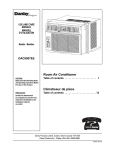
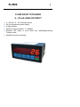
6/0; | FLOW RATE TOTALIZER 4…20 mA ANALOG INPUT 4…20 mA o 0...10V analogue inputs 24 Vdc transmitter power supply 6-digit indicator Maximum range totalizer: 0...999999 External (IN1 input) or local Reset key (disabling/enabling) Totalizer reset Suitable for panel mounting 1.0 PACKING LIST user's manual warnings apparatus two fixing clamps one extractable 12 pole terminal blocks (into the unit) 2.0 SAFETY PRECAUTIONS Before using the instrument read the warnings supplied with the product (see 1.0 Packaging list) ad all is indicated below. The instrument is a electronic component and you don’t have to be esteemed it a machine. If the instrument is utilised as a part of a machine, it can’t work if the entire machine doesn’t fulfil the relative directive. The instrument marking doesn’t dispense the customer to fulfil the law obligations relatives the entire machine. Preventively make sure that the instrument model matches with the appropriate power supply voltage (see 4.5 paragraph). Insert a adequate protection on power supply circuits; we recommend a 100 mA fuse protection with medium retard intervention. The instrument is exempt to fulmination phenomenon (internal “surge” protection). By pressing any buttons you will stop the positioning process. The instrument is a electronic component and can’t replace a mechanical safety device. The manufacturer refuse all responsibility in order to a possible malfunction. Preventively make sure that the instrument model matches with the appropriate power supply voltage (see 4.5 paragraph). 3.0 GENERAL DESCRIPTION The unit, in conjunction with the transmitter (4...20 mA or 0...10V), is designed for accurate measurement and total flow. 4.0 PREPARATION FOR THE USE 4.1 FIRST STEP The unit is setted up for panel mounting. It is fixed in place with the two clamps provided. The maximum permitted panel thickness is 4 mm. Make all electrical connections with power supply off. Take care to ensure electrical connections are correct. 4.2 ASSEMBLY AND INSTALLATION Insert the instrument in the panel. It is fixed in place with the two clamps provided. Insert the clamps into the button-holes in the right and left sides of the instrument and put them in tension turning the pin with a screw-driver (slot or cross, 4 mm). Make all electrical connections are correct as showed in the schemas below. 4.3 FRONTAL VIEW 1= 2= 3= 4= 6-digit reading indicator (character high 12.5 mm) 9 millimetres display show the label of parameter during programming PGM programming access key Dual function RESET/ENTER key: used for reset during normal operation enter data during programming 5= UP arrow key. Used to change selected digit 6= SHIFT arrow key with two functions 7= not enabled 8= not enabled 9= not enabled 10= not enabled 4.4 REAR VIEW AND CONNECTIONS 4.5 POWER SUPPLY Preventively make sure that the instruments model matches with the appropriate power supply voltage Model Power supply Notes 6/0;6 6/0;6 6/0;6 6/0;6 115 Vac 230 Vac 24 Vac 24 Vdc Tolerance: ± 10% Tolerance: ± 10% Tolerance: ± 10% Range 12….30 Vdc All data are stored in a E2PROM static memory therefore they are kept with power off. 4.6 ELECTRICALS CONNECTIONS Two removable 12+6 pole terminal blocks are provided at the rear of the instrument for electrical connections (see Figure 2). 4.6.1 POWER SUPPLY 24 Vdc to terminals 0 (negative) e 24 (positive) 24 Vac to terminals 0 e 24 115 Vac to terminals 0 e 110 230 Vac to terminals 0 e 220 Connect ground to associated terminal 4.6.2 DIGITAL INPUT IN1 input: zero totalizer contact between IN1 and COM 4.6.3 CONNECTION OF ANALOG INPUT See figures 3, 4, 5 4.7 FUNCTION TEST Apply power supply. The display is on and show zero. 4.8 CALIBRATION PROGRAMMING Default calibration: input : 4…20 mA total flow : 0...1000. The calibration operation makes it possible to associate two value for the input variable (start and end of scale) with the two reading values programmed for the parameters "start of scale reading" and "end of scale reading" in the configuration programs. This operation must be execute only if necessary: calibrate the signal in input (for example change signal input from 4…20 mA to 0…10V) recalibrate the device (periodic calibration) correct the input signal at the connect transmitter 4.8.1 KEYBOARD PROCEDURE To access calibration, hold down the PGM key for around three seconds after the last configuration programming step. To perform this operation, indicator must be connected with the input variable (real or calibrator). Set analogue input to start of scale. Enter calibration mode. The display will indicate "tar.IS": press ENTER to calibrate start of scale, or press PGM to pass to end of scale calibration. If ENTER is pressed, the display will indicate "attend" (wait) while the unit the operation required for calibration (this may take some time, particularly if the variable is not perfectly stable). After data acquisition, the display will show "tar.FS". Enter the end of scale value. Press ENTER to calibrate end of scale. To exit from calibration programming, press PGM. If ENTER is pressed, the display will indicate "attend" (wait) while the unit the operation required for calibration (this may take some time, particularly if the variable is not perfectly stable). 5.0 INSTRUCTION FOR THE OPERATION After the start up operation the instrument is ready. The device measures the signal applied at the input, integrates it according to the set parameters, The maximum scale totalizer is 0 ... 999999 . Reached full scale, it resets and restarts . The totalized value is stored in the EEPROM memory at the power off. 5.1 EXAMPLE OF INTEGRATION input signal: 4…20 mA ; settings hourly capacity: 0...3000 l/h 4 mA : 0 litres / hour 20 mA : 3000 litres / hour With a constant input to 12 mA indicator has totaled in an hour , 1500 pulses ; the display is increased by one unit every 2.4 seconds . 5.2 LOCAL RESET Zeroing can be implemented using the front button RESET / ENTER ( after enabling parameter " F " to one) . The action can be : immediate : the totalized value is reset when you press the RESET / ENTER delayed ( by setting the parameter "A " to one) : the sum total value is reset with a continuous pressure of three seconds of the RESET / ENTER 5.3 REMOTE RESET The reset can be implemented by means of the digital input IN1 . The signal should be a clean contact . 5.4 CONFIGURATION MENÙ The following configurations are available: Description Hour count at 0 mA Hour count at 20 mA Decimal point Reset key Immediate or delayed reset key Dead band at starting scale Label E L d F A b Range Min 0 0 0 0 0 0,0 Max 999999 999999 6 1 1 10,0 Default 0 1000 0 0 0 0,1 To access configuration press PGM key. Display will show "C 000000", while units will flash. To access programming, enter pass code "210" and confirm with PGM. If the wrong number is entered it is will not be accepted; when the ENTER or PGM keys are pressed the display will show the count again. After each configuration step: press PGM to move on the next programming step or press ENTER to return to the count display. CODE “E” - HOUR COUNT AT 0 mA Set the number (normally is zero). Number must be between 0 and 999999. CODE “L” - HOUR COUNT AT 20 mA Set the number. Number must be between 0 and 999999. CODE “d” - DECIMAL POINT Set one of the following numbers: 0 = No decimal point 1 = Decimal point at far right 2 = One decimal place 3 = Two decimal places 4 = Three decimal places 5 = Four decimal places 6 = Five decimal places 999999 999999. 99999.9 9999.99 999.999 99.9999 9.99999 CODE “F” - RESET/ENTER KEY FUNCTION Select function: 0 = disabled 1 = enable to display reset CODE “A” - IMMEDIATED OR DELAYED FRONTAL RESET Set one of the following numbers: 0 = Immediate reset key 1 = Front reset key active only if held down for three seconds CODE “b” - DEAD BAND AT STARTING SCALE Configure the percentage of dead band at starting of scale. When input value is into the dead band total value doesn't increase. This parameter is useful for to correct the imprecision at the start scale of measurement and ensure no increase without input signal. 5.5 MANUAL COMMAND The device has the following manual command (see Fig. 1): 3 = PGM programming access key. 4 = Dual function RESET/ENTER key: used for reset during normal operation, enter data during programming. 5 = UP arrow key. Used to change selected digit. 6 = SHIFT arrow key. Used to move selected digit during programming, 5.6 REMOTE COMMANDS There are the following remote command: 4…20 mA analog input Digital input 5.6.1 ANALOG INPUT DC current with 4…20 mA range Input impedance 100 ohm Max overload 100% constant Maximum length cables: 3 meters. 5.6.2 DIGITAL INPUT (IN1) not powered contact or static NPN Voltage max 24 volt Current max 6 mA Maximum length cables: 3 meters. 5.7 &$/,%5$7,21)5(48(1&< 5HFDOLEUDWHHYHU\WZR\HDUVLVUHFRPPHQGHG. 5.8 0$,17(1$1&( ,QWKHGHYLFHWKHUHDUHQRSDUWVWKDWUHTXLUHPDLQWHQDQFH. 6.0 TECHNICAL SPECIFICATIONS 6.1 GENERAL FEATURES PACKAGE INDICATOR Case panel mount 96 x 48 mm; frontal, IP54 Cut-out dimensions 92 x 45 mm Depth 100 mm (terminal blocks included) Case material Noryl Weight 450 g, ac models (300 g, dc model) Keyboard: 4 membrane pushbuttons Connections by two extractable 12+6 poles terminal block 6-digits display Maximum range: 0…999999 20.000 points A/D converter resolution Average conversion time 250 ms ANALOG INPUT Input terminal configuration: - 0...± 40 mA impedance 100 ohm - 4...20 mA impedance 100 ohm - 0... ±4 V impedance 10 kohm - 0... ±40 V impedance 110 kohm Maximum overload 100 % constant POWER SUPPLY Power supply as per code: 115 Vac; 230 Vac; 24 Vac; 24 Vdc Frequency (AC): 50/60 Hz Max consumption 3,3 VA (3,3W) E²EPROM static memory at power off. TRANSMITTER POWER SUPPLY AC power models DC power DIGITAL INPUT (IN1) One optocoupled reset input Not powered contact or static NPN Voltage max 24 volt Current max 6 mA 6.2 AMBIENTAL CONDITIONS 6.2.1 TEMPERATURE Operating temperature –10…+50°C 6.2.2 HUMIDITY Relative humidity 0…95% not condensing 6.2.3 EMC COMPLIANCE EEC Directive 2004/108 EN61000-6-2 Generic standard immunity industrial environment EN61000-6-4 Generic standard emission industrial environments 6.2.4 LVD COMPLIANCE Directive 2006/95 / EC EN61010-1 Safety requirements 6.3 STORAGE Storage temperature -20… +70°C Relative humidity 0…95% not condensing You should preferably utilise dry and clean environment. Avoid any corrosive acid exhalation exposure. Do not wash the apparatus with water. Avoid any liquid entry. : output 24 Vdc : power in 6.4 ACCESSORIES AND OPTIONS There isn’t any optional for this device. :DUUDQW\ 3URGXFWVVXSSOLHGE\6*0/(.75$DUHJXDUDQWHHGIRUDSHULRGRI WZHOYH PRQWKVIURPGHOLYHU\GDWH DFFRUGLQJWRWKHFRQGLWLRQVVSHFLILHGLQRXUVDOHFRQGLWLRQVGRFXPHQW 6*0/(.75$FDQFKRRVHWRUHSDLURUUHSODFHWKH3URGXFW ,IWKH3URGXFWLVUHSDLUHGLWZLOOPDQWHLQWKHRULJLQDOWHUPRIJXDUDQWHHZKHUHDVLIWKH3URGXFWLVUHSODFHGLW ZLOOKDYH WZHOYH PRQWKVRIJXDUDQWHH 7KHZDUUDQW\ZLOOEHQXOOLIWKH&OLHQWPRGLILHVUHSDLURUXVHVWKH3URGXFWVIRURWKHUSXUSRVHVWKDQWKHQRUPDO FRQGLWLRQVIRUHVHHQE\LQVWUXFWLRQVRU&RQWUDFW ,QQRFLUFXPVWDQFHVVKDOO6*0/(.75$EHOLDEOHIRUGLUHFWLQGLUHFWRUFRQVHTXLHQWLDORURWKHUORVVRU GDPDJHZKHWKHUFDXVHGE\QHJOLJHQFHRQWKHSDUWRIWKHFRPSDQ\RULWVHPSOR\HHVRURWKHUZLVHKRZVRHYHU DULVLQJRXWRIGHIHFWLYHJRRGV )DFWRU \7HVW&HUWLFDWH ,QFRQIRUPLW\WRWKHFRPSDQ\DQGFKHFNSURFHGXUHV,FHUWLI\WKDWWKHHTXLSPHQW 6/0; 3URGXFWLRQDQGFKHFNGDWH LVFRQIRUPWRWKHWHFKQLFDOUHTXLUHPHQWVRQ7HFKQLFDO'DWDDQGLWLVPDGHLQFRQIRUPLW\WRWKH6*0/(.75$ SURFHGXUH Serial n. Quality Control Manager SGM-LEKTRA S.r.l. Via Papa Giovanni XXIII, 49 20090 Rodano (MI) - ITALY tel: ++39 02 95328257 fax: ++39 02 95328321 e-mail: [email protected] web: sgm-lektra.com